カテゴリ
- 学童・教育用品(9)
絞り込み
ブランド
- SPARKFUN
- モノタロウ(5)
- 日東工器(14)
- AMPHENOL(5)
- TRUSCO(2)
- イマオコーポレーション(1)
- omron(オムロン)(1)
- オムロンヘルスケア(1)
- 中部高圧ホース(1)
- MICROCHIP(1)
- DIGILENT(1)
- RS PRO(1)
「2 tsm sus」の検索結果
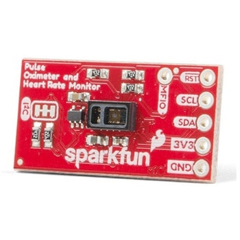
SparkFun Pulse Oximeter and Heart Rate Sensor - MAX30101 & MAX32664 Qwiic
SPARKFUN¥13,980税込¥15,3781個33日以内出荷Description。The SparkFun Pulse Oximeter and Heart Rate Sensor is an I2C based biometric sensor, utilizing two chips from Maxim Integrated:the MAX32664 Biometric Sensor Hub and the MAX30101 Pulse Oximetry and Heart Rate Module. While the latter does all the sensing, the former is an incredibly small and fast Cortex M4 processor that handles all of the algorithmic calculations, digital filtering, pressure/position compensation, advanced R-wave detection, and automatic gain control. We've provided a Qwiic connector to easily connect to the I2C data lines but you will also need to connect to two additional lines. This board is very small, measuring at 1in×0.5in(25.4mm×12.7mm), which means it will fit nicely on your finger without all the bulk.。The MAX30101 does all the sensing by utilizing its internal LEDs to bounce light off the arteries and arterioles in your finger's subcutaneous layer and sensing how much light is absorbed with its photodetectors. This is known as photoplethysmography. This data is passed onto and analyzed by the MAX32664 which applies its algorithms to determine heart rate and blood oxygen saturation(SpO2). SpO2 results are reported as the percentage of hemoglobin that is saturated with oxygen. It also provides useful information such as the sensor's confidence in its reporting as well as a handy finger detection data point. To get the most out of the sensor we've written an Arduino Library to make it easy to adjust all the possible configurations.。The SparkFun Qwiic connect system is an ecosystem of I2C sensors, actuators, shields and cables that make prototyping faster and less prone to error. All Qwiic-enabled boards use a common 1mm pitch, 4-pin JST connector. This reduces the amount of required PCB space, and polarized connections mean you can't hook it up wrong.。Get Started with the Pulse Oximeter and Heart Rate Monitor Hookup Guide。Features。SparkFun Pulse Oximeter and Heart Rate Sensor。MAX30101 and MAX32664 sensor and sensor hub。Qwiic connectors for power and I2C interface。I2C Address:0x55。MAX30101 - Pulse Oximeter and Heart-Rate Sensor。Heart-Rate Monitor and Pulse Oximeter Sensor in LED Reflective Solution。Integrated Cover Glass for Optimal, Robust Performance。Ultra-Low Power Operation for Mobile Devices。Fast Data Output Capability。Robust Motion Artifact Resilience。MAX32664 - Ultra-Low Power Biometric Sensor Hub。Biometric Sensor Hub Solution。Finger-Based Algorithms Measure Pulse Heart Rate and Pulse Blood Oxygenation Saturation(SpO2)。Both Raw and processed data are available。Basic Peripheral mix optimizes size and performanceアズワン品番67-0426-96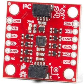
SparkFun 9DoF IMU Breakout - ICM-20948 Qwiic
SPARKFUN¥7,298税込¥8,0281個33日以内出荷。Description。The SparkFun 9DoF IMU Breakout incorporates all the amazing features of Invensense's ICM-20948 into a Qwiic-enabled breakout board complete with a logic shifter and broken out GPIO pins for all your motion sensing needs. The ICM-20948 itself is an extremely low powered, I2C and SPI enabled 9-axis motion tracking device that is ideally suited for smartphones, tablets, wearable sensors, and IoT applications. Utilizing our handy Qwiic system, no soldering is required to connect it to the rest of your system. However, we still have broken out 0.1"-spaced pins in case you prefer to use a breadboard.。In addition to the 3-Axis Gyroscope with four selectable ranges, 3-Axis Accelerometer, again with four selectable ranges, and 3-axis magnetometer with an FSR to ±4900μT, the ICM-20948 also includes a Digital Motion Processor that offloads the computation of motion sensing algorithms from the detectors, allowing optimal performance of the sensors. We've also broken out all the ICM-20948 pin functionality to GPIO and labeled them I2C on the front, SPI on the back for ease of identification.。Note:The I2C address of the ICM-20948 is 0x69 and is jumper selectable to 0x68. A multiplexer/Mux is required to communicate to multiple ICM-20948 sensors on a single bus. If you need to use more than one ICM-20948 sensor consider using the Qwiic Mux Breakout.。The SparkFun Qwiic Connect System is an ecosystem of I2C sensors, actuators, shields and cables that make prototyping faster and less prone to error. All Qwiic-enabled boards use a common 1mm pitch, 4-pin JST connector. This reduces the amount of required PCB space, and polarized connections mean you can't hook it up wrong.。Need a custom board? This component can be found in SparkFun's A La Carte board builder. You can have a custom design fabricated with this component - and your choice of hundreds of other sensors, actuators and wireless devices - delivered to you in just a few weeks.。Get Started with the SparkFun ICM-20948 9DoF IMU Guide。Features。1.95 V to 3.6 V supply voltage。Triple-axis MEMS gyroscope with user-programmable full-scale range of ±250 dps, ±500 dps, ±1000 dps, and ±2000 dps。Triple-axis MEMS accelerometer with programmable full scale range of ±2g, ±4g, ±8g, and ±16g。Triple-axis silicon monolithic Hall-effect magnetic sensor with full scale measurement range to ±4900 μT。I2C at up to 100 kHz(standard-mode)or up to 400 kHz(fast-mode)or SPI at up to 7 MHz for communicationwith registers。On-board digital motion processor(DMP)。Digital-output temperature sensor。2x Qwiic Connection Ports。I2C Address:0x69(0x68 with Jumper)。。Documents。Schematic。Eagle Files。Hookup Guide。Datasheet(ICM-20948)。Arduino Library。Python Support(Qwiic_Py)。GitHub Hardware Repoアズワン品番67-0427-05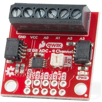
QWIIC 12BIT 4CHANNEL ADS1015
SPARKFUN¥5,498税込¥6,0481個33日以内出荷Description。A lot of the time you just need to add more analog inputs to solve a problem. It happens. The SparkFun Qwiic 12 Bit ADC can provide four channels of I2C controlled ADC input to your Qwiic enabled project. These channels can be used as single-ended inputs, or in pairs for differential inputs. What makes this even more powerful is that it has a programmable gain amplifier that lets you "zoom in" on a very small change in analog voltage(but will still effect your input range and resolution). Utilizing our handy Qwiic system, no soldering is required to connect it to the rest of your system. However, we still have broken out 0.1"-spaced pins in case you prefer to use a breadboard.。The ADS1015 uses its own internal voltage reference for measurements, but a ground and 3.3V reference are also available on the pin outs for users. This ADC board includes screw pin terminals on the four channels of input, allowing for solderless connection to voltage sources in your setup. It also has an address jumper that lets you choose one of four unique addresses(0x48, 0x49, 0x4A, 0x4B). With this, you can connect up to four of these on the same I2C bus and have sixteen channels of ADC. The maximum resolution of the converter is 12-bits in differential mode and 11-bits for single-ended inputs. Step sizes range from 125μV per count to 3mV per count depending on the full-scale range(FSR)setting.。We have included an onboard 10K trimpot connected to channel A3. This is handy for initial setup testing and can be used as a simple variable input to your project. But don't worry, we added an isolation jumper so you can use channel A3 however you'd like.。Note:The I2C address of the ADS1015 is 0x48 and is jumper selectable to 0x49, 0x4A, 0x4B. A multiplexer/Mux is required to communicate to multiple ADS1015 sensors on a single bus. If you need to use more than one ADS1015 sensor consider using the Qwiic Mux Breakout.。The SparkFun Qwiic connect system is an ecosystem of I2C sensors, actuators, shields and cables that make prototyping faster and less prone to error. All Qwiic-enabled boards use a common 1mm pitch, 4-pin JST connector. This reduces the amount of required PCB space, and polarized connections mean you can't hook it up wrong.。Get Started with the SparkFun Qwiic 12-Bit ADC Hookup Guide。Features。ADS1015。Operating Voltage(VDD):2.0V-5.5V。(Note:When powering with a Qwiic cable, the input range is only 3.3v)。Operating Temperature:-40℃ to 125℃。Operation Modes:Single-Shot, Continuous-Conversion(Default), and Duty Cycling。Analog Inputs:Measurement Type:Single-Ended(Default)。Input Voltage Range:GND to VDD。Full Scale Range(FSR):±.256V to ±6.114V(Default:2.048V)。Resolution:12-bit(Differential)or 11-bit(Single-Ended)。LSB size:0.125mV - 3mV(Default:1 mV)。Sample Rate:128 Hz to 3.3 kHz(Default:1600SPS)。Current Consumption(Typical):150μA-200μA。I2C Address:0x48(Default), 0x49, 0x4A, or 0x4B。Screw pin terminals for solderless connection to voltage sources。Four unique I2C addresses:0x48。0x49。0x4A。0x4B。2x Qwiic connection ports。Onboard 10K trimpotアズワン品番67-0360-13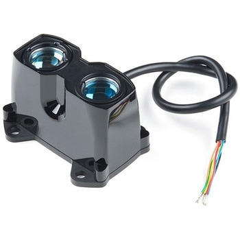
LIDAR-Lite v3HP
SPARKFUN¥49,980税込¥54,9781個33日以内出荷Description。LIDAR has never looked so good! This is the LIDAR-Lite v3HP, a compact, high-performance optical distance measurement sensor from Garmin(TM). The LIDAR-Lite v3HP is。the。ideal optical ranging solution for drone, robot, or unmanned vehicle applications. Each sensor is housed in a durable, IPX7-rated housing and includes all the core features and user configurability of the popular LIDAR-Lite v3.。The v3HP is very similar in function to that of the v3 but it can now sample faster at rates greater than 1kHz(where as the v3 is only capable of up to 500Hz). Another improvement is that this v3HP model is more power efficient with current consumption rates 40mA less than the v3(that's 65mA as opposed to 105mA while idle, and 85mA instead of 130mA while acquiring).。Each LIDAR-Lite v3HP has a range of 1m to 40m and features an edge-emitting, 905nm(1.3 watts), single-stripe laser transmitter, 8m Radian beam divergence, and an optical aperture of 12.5mm. This version of the LIDAR-Lite still operates at 5VDC(6V max)with a peak power of 1.3W and still possesses an accuracy of +/- 2.5cm at >2m. On top of everything else, the LIDAR-Lite is user-configurable, allowing adjustment between accuracy, operating range and measurement time and can be interfaced via I2C or PWM with the attached 200mm cable.。Note:CLASS 1 LASER PRODUCT CLASSIFIED EN/IEC 60825-1 2014. This product is in conformity with performance standards for laser products under 21 CFR 1040, except with respect to those characteristics authorized by Variance Number FDA-2016-V-2943 effective September 27, 2016.。Get Started with the LIDAR-Lite v3HP Guide。Features。Resolution:1 cm。Typical accuracy:+/- 2.5cm at distances greater than 2 meters(Refer to operating manual for complete operating specifications)。Range:1m to 40m。Update rate:Greater than 1kHz。Interface:I2C or PWM。Power(operating voltage):4.75-5VDC; 6V Max。Current consumption:65ma idle; 85ma during acquisition。Operating temperature:-20℃ to 60℃。Laser wave length/Peak power:905nm/1.3W。Beam divergence:8m Radian。Optical aperture:12.5mm。Water rating:IPX7。Unit dimensions:24.5mm×53.5mm×33.5mm(1.0in×2.1in×1.3in)。Weight:34g(1.2oz)アズワン品番67-0426-76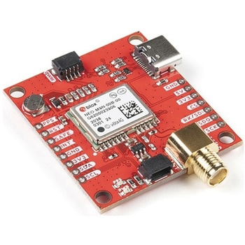
SparkFun GPS Breakout - NEO-M9N, SMA Qwiic
SPARKFUN¥22,980税込¥25,2781個33日以内出荷Description。The SparkFun NEO-M9N GPS Breakout is a high quality GPS board with equally impressive configuration options including SMA. The NEO-M9N module is a 92-channel u-blox M9 engine GNSS receiver, meaning it can receive signals from the GPS, GLONASS, Galileo, and BeiDou constellations with ~1.5 meter accuracy. This breakout supports concurrent reception of four GNSS. This maximizes position accuracy in challenging conditions increasing, precision and decreases lock time; and thanks to the onboard rechargeable battery, you'll have backup power enabling the GPS to get a hot lock within seconds! Additionally, this u-blox receiver supports I2C(u-blox calls this Display Data Channel)which makes it perfect for the Qwiic compatibility so we don't have to use up our precious UART ports. Utilizing our handy Qwiic system, no soldering is required to connect it to the rest of your system. However, we still have broken out 0.1"-spaced pins in case you prefer to use a breadboard.。The NEO-M9N module detects jamming and spoofing events and can report them to the host, so that the system can react to such events. A SAW(Surface Acoustic Wave)filter combined with an LNA(Low Noise Amplifier)in the RF path is integrated into the NEO-M9N module which allows normal operation even under strong RF interferences.。U-blox based GPS products are configurable using the popular, but dense, windows program called u-center. Plenty of different functions can be configured on the NEO-M9N:baud rates, update rates, geofencing, spoofing detection, external interrupts, SBAS/D-GPS, etc. All of this can be done within the SparkFun Arduino Library!。The SparkFun NEO-M9N GPS Breakout is also equipped with an on-board rechargeable battery that provides power to the RTC on the NEO-M9N. This reduces the time-to-first fix from a cold start(~24s)to a hot start(~2s). The battery will maintain RTC and GNSS orbit data without being connected to power for plenty of time.。This product requires an antenna:Be sure to check out the related products/hookup accessories and pick a suitable SMA antenna for your project.。The SparkFun Qwiic Connect System is an ecosystem of I2C sensors, actuators, shields and cables that make prototyping faster and less prone to error. All Qwiic-enabled boards use a common 1mm pitch, 4-pin JST connector. This reduces the amount of required PCB space, and polarized connections mean you can't hook it up wrong.。The NEO-M9N GPS Breakout can also be automatically detected, scanned, configured, and logged using the OpenLog Artemis datalogger system. No programming, soldering, or setup required!。Get Started With the SparkFun NEO-M9N GPS Guide。Features。Integrated SMA connector for use with antenna of your choice。92-Channel GNSS Receiver。1.5m Horizontal Accuracy。25Hz Max Update Rate(four concurrent GNSS)。Time-To-First-Fix:Cold:24s。Hot:2s。Max Altitude:80,000m。Max G:≦4。Max Velocity:500m/s。Velocity Accuracy:0.05m/s。Heading Accuracy:0.3 degrees。Time Pulse Accuracy:30ns。3.3V VCC and I/O。Current Consumption:~31mA Tracking GPS+GLONASS。Software Configurable。Geofencing。Odometer。Spoofing Detection。External Interrupt。Pin Control。Low Power Mode。Many others!。Supports NMEA, UBX, and RTCM protocols over UART or I2C interfacesアズワン品番67-0423-87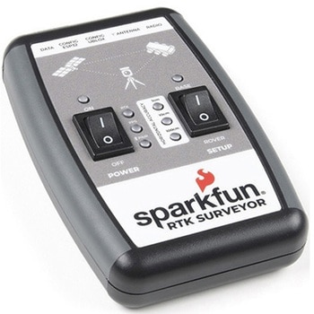
SparkFun RTK Surveyor
SPARKFUN¥129,800税込¥142,7801個33日以内出荷Description。The SparkFun RTK Surveyor is an easy to use GNSS receiver for centimeter-level positioning. Perfect for surveying, this preprogrammed device can also be used for autonomous driving, navigation, asset tracking and any other application where there is a clear view of the sky. The RTK Surveyor can also be used as a base station. With the flick of a switch, two RTK Surveyors can be used to create an RTK system capable of 14mm horizontal positional accuracy. The built-in Bluetooth(R)connection via an ESP32 WROOM enables the user to use the RTK Surveyor with their choice of GIS application on a phone or tablet. The built in battery allows field use for up to four hours and is compatible with common USB battery banks.。This device can be used in four modes:GNSS Positioning(~30cm accuracy)。GNSS Positioning with RTK(1.4cm accuracy)。GNSS Base Station。GNSS Base Station NTRIP Server。In Position mode the device receives L1/L2 signals from a user-provided antenna and the high-grade GNSS receiver provides lat/long and altitude with accuracies around 300mm.。In Positioning with RTK mode the device receives L1/L2 signals from the antenna and correction data from a base station. The correction data can be obtained from a cellular link to online correction sources or over a radio link to a 2nd RTK Surveyor setup as a base station.。In Base Station mode the device is mounted to a temporary position(like a tripod)and begins transmitting correction data over a radio or internet connection. A base is often used in conjunction with a second unit set to 'Positioning with RTK' to obtain the 14mm relative accuracy.。In Base Station NTRIP Server mode the device is mounted to a semi or permanently fixed position(like a roof)and connects over WiFi to transmit the correction data to a NTRIP caster so that any rover can access the correction data over a cellular or internet connection. This type of base is a very easy way to setup a very precise absolute correction source.。Two cables are provided with the RTK Surveyor allowing a user to plug on our easy to use Serial Telemetry Radios or their own radio link. If a local correction source is within 10km, a user can also use their phone to provide correction data over the Bluetooth(R)link(no external radio needed!).。Note:The SparkFun RTK Surveyor is just the enclosed device and does NOT include an antenna, serial telemetry radio, or associated mounting pieces. These items will need to be purchased separately from the Hookup Accessories below.。Get Started With the SparkFun RTK Surveyor Guide。Features。GNSS Receiver:ZED-F9P。Concurrent reception of GPS, GLONASS, Galileo and BeiDou。Receives both L1C/A and L2C bands。Current:68mA - 130mA(varies with constellations and tracking state)。Time to First Fix:25s(cold), 2s(hot)。Max Navigation Rate:PVT(basic location over UBX binary protocol)- 25Hz。RTK - 20Hz。Raw - 25Hz。Horizontal Position Accuracy:2.5m without RTK。0.010m with RTK。Max Altitude:50km(31 miles)。Max Velocity:500m/s(1118mph)。Bluetooth(R)Transceiver:ESP32 WROOM。Xtensa(R)dual-core 32-bit LX6 microprocessor。Up to 240MHz clock frequency。16MB of flash storage。520kB internal SRAM。Integrated 802.11 BGN WiFi transceiver。Integrated dual-mode Bluetooth(R)(classic and BLE)。Hardware accelerated encryption(AES, SHA2, ECC, RSA-4096)。2.5 μA deep sleep current。Overall Device。Internal Battery:LiPo 1000mAh with 500mA charging。Radio Port:3.3V TTL Serial(57600bps RTCM TX/RX)。Data Port:3.3V TTL Serial(115200bps NMEA)。Weight:132g(entire device including battery)。Dimensions:118mm×79mm×30mm(4.7in×3.1in×1.2in)。1x Qwiic Connector。1x microSD Socket for optional logging。Changes:This version(which replaces SPX-17369)uses a reinforced edge mount SMA connector for better resiliency when a fixed 'stub' antenna is used.アズワン品番67-0423-95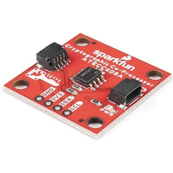
SparkFun Cryptographic Co-Processor Breakout - ATECC608A Qwiic
SPARKFUN¥1,498税込¥1,6481個33日以内出荷。Description。Product Restrictions:To access certain features of the ATECC608A, users will need to contact Microchip and sign an NDA contract to obtain the complete datasheet. Due to the required NDA - technical support, an Arduino library, and hookup guide are not provided for users on this product.。The SparkFun ATECC608A Cryptographic Co-processor Breakout allows you to add strong security to your IoT node, edge device, or embedded system. This includes。a。symmetric。authentication,。symmetric。AES-128 encryption/decryption, and much more. As stated above, the ATECC608A has limited Arduino support and the complete datasheet is under NDA with Microchip.。This breakout board includes two Qwiic ports for plug and play functionality. Utilizing our handy Qwiic system, no soldering is required to connect it to the rest of your system. However, we still have broken out 0.1"-spaced pins in case you prefer to use a breadboard. The ATECC608A chip is capable of many cryptographic processes, including, but not limited to:Creating and securely storing unique asymmetric key pairs based on Elliptic Curve Cryptography(FIPS186-3).。AES-128:Encrypt/Decrypt, Galois Field Multiply for GCM。Creating and verifying 64-byte digital signatures(from 32-bytes of message data).。Creating a shared secret key on a public channel via Elliptic Curve Diffie-Hellman Algorithm.。SHA-256 HMAC Hash including off-chip context save/restore。Internal high quality FIPS random number generator.。Embedded in the chip is a 10Kb EEPROM array that can be used for storing keys, certificates, data, consumption logging, and security configurations. Access to the sections of memory can then be restricted and the configuration locked to prevent changes. Each ATECC608A Breakout ships with a guaranteed unique 72-bit serial number and includes several security features to prevent physical attacks on the device itself, or logical attacks on the data transmitted between the device.。A summary datasheet for the ATECC608A is available here. The full datasheet is under NDA with Microchip. You will need to contact them for access to the entire datasheet. Meanwhile, the ArduinoATECCX08 Library currently only supports the ATECC608A with SAMD21 Arduino boards.。We do have much more support for the ATECC508A version of this chip. Please check out our ATECC508A Hookup Guide and Arduino Library(which includes six examples). This will get you familiar with the basics of elliptic curve cryptography and signing/verifying data with the ATECC508A version of the chip.。Note:The I2C address of the ATECC608A is 0x60 and is software-configurable to any address. A multiplexer/Mux is required to communicate to multiple ATECC608A sensors at the default address when on a single bus. If you need to use more than one ATECC608A sensor at the default address, consider using the Qwiic Mux Breakout.。Note:The ATECC608A can be only configured once before it is。PERMANENTLY。locked。. It is advisable that users purchase multiple boards in order to use other configurations and explore the advanced functions of the ATECC608A.。Additionally, this board。IS。capable of encrypting and decrypting data. However, to access these additional features, you will need to contact Microchip and sign an NDA contract to obtain the complete datasheet.。It is recommended that an SparkFun RedBoard Turbo - SAMD21 Development Board is used with this product due to the buffer size required on the I2C bus.。The SparkFun Qwiic Connect System is an ecosystem of I2C sensors, actuators, shields and cables that make prototyping faster and less prone to error. All Qwiic-enabled boards use a common 1mm pitch, 4-pin JST connector. This reduces the amount of required PCB space, and polarized connections mean you can't hook it up wrong.。。Features。Operating Voltage:2.0V-5.5V(。Default on Qwiic System:3.3V。)。Active Current Draw(for ATECC608A):16 mA。Sleep Current(for ATECC608A):<150 nA。Guaranteed Unique 72-bit Serial Number。10 Kb EEPROM Memory for Keys, Certificates, and Data。Storage for up to 16 Keys。256-bit Key Length。Internal High-Quality FIPS Random Number Generator(RNG)。Configurable I2C Address(7-bit):0x60(。Default。)アズワン品番67-0423-59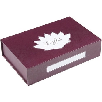
SparkFun Large Parts Box - LilyPad Magnetic
SPARKFUN¥2,598税込¥2,8581個33日以内出荷。Description。When you're working with e-textiles, you have a tendency to collect a lot of small parts:LilyPad boards, bobbins, needles...the tools of the trade. Why not pick up a sturdy box to keep your bits and pieces off the floor? This large LilyPad-branded box is made from rigid cardboard printed with a fancy tone-on-tone pattern, label space and the LilyPad logo. There are even magnetic closures embedded in the lid.。We like this box because it's rigid enough to throw in a sewing bag and also looks good on a workbench or makerspace. With an inside dimension of 2 inches deep, it's big enough for batteries, fabric swatches and whatever small parts you have floating around. It also makes a great gift box if you're thinking about getting someone the gift of LilyPad!。Features。Dimensions:10.0"×6.3"×2.3"アズワン品番67-0428-15
PureThermal Mini Pro JST-SR with FLIR Lepton 3.5
SPARKFUN¥129,800税込¥142,7801個33日以内出荷Description。The new PureThermal Mini Pro JST-SR with Thermal by FLIR is a hackable thermal camera for the FLIR Lepton thermal imaging camera core. Just like its PureThermal 2 predecessor, it ships pre-configured to operate as a plug-and-play UVC 1.0 USB thermal webcam that will work with standard webcam and video apps on all major platforms using a JST-SR to USB Cable, or your own custom cable. For developers, its reference firmware and viewer software are open source.。It has multiple connection options such as solder straight to the board or a custom cable using the JST-SR port. The PTMini Pro also features four mounting holes, less complex circuitry, and perhaps best of all, USB DFU. This is a development kit ready to be embedded into a production system.。Each board comes with a FLIR Lepton 3.5.。The FLIR Lepton(R)is a radiometric-capable LWIR camera solution that is smaller than a dime, fits inside a smartphone, and is one tenth the cost of traditional IR cameras. Using focal plane arrays of either 160x120 or 80x60 active pixels, Lepton easily integrates into native mobile-devices and other electronics as an IR sensor or thermal imager. The radiometric Lepton captures accurate, calibrated, and noncontact temperature data in every pixel of each image.。Features。PureThermal:Compatible with all production FLIR Leptons, including radiometric 2.5 and 3.5 cores。9 Hz color video over usb using the USB UVC class。STM32F412 ARM microprocessor - execute on-board image processing without need for an external system。Open source reference firmware:GroupGets PureThermal Github。Works with GetThermal - our custom open source thermal video display software for macOS and Linux with radiometric support。DFU over USB using a JST-SR port to USB cable, or a modified USB cable and the through holes.。Four mounting holes。Compact form-factor ready to be embedded into production systems。FLIR Lepton 3.5:Thermal sensitivity:< 50 mK(0.050℃)。Spectral Range:8 - 14 microns(nominal)Long Wave Infrared(LWIR)。Resolution:160h×120v pixels。Radiometric Accuracy - High Gain Mode:Greater of +/- 5℃ or 5%(typical); Low Gain Mode:Greater of +/- 10℃ or 10%(typical)。Scene Dynamic Range - High Gain Mode:-10° to +140℃; Low Gain Mode:-10° to +400℃(at room temperature), -10° to +450℃(typical)。Pixel Size:12 micrometers。Frame Rate:8.7 Hz(effective)。Output Format:User-selectable 14-bit, 8-bit(AGC applied), or 24-bit RGB(AGC and colorization applied)。Horizontal Field of View(HFOV):57°。Lens Type:f/1.1。Size(w×l×h):10.50×12.70×7.14 mm。Weight:0.9 grams。Power Consumption:150 mW typical, 650 mW during shutter event, 5mW standby。Optimum Operating Temperature Range:-10℃ to + 80℃アズワン品番67-0423-44