カテゴリ
- 学童・教育用品(69)
- 制御機器(5)
- 空調・照明・電設資材(2)
- パソコン/周辺機器(1)
絞り込み
ブランド
- SPARKFUN
- ホンダ(452)
- RS PRO(313)
- Optibelt(119)
- サンワサプライ(112)
- StarTech.com(86)
- Delta Plus(デルタプラス)(73)
- エレコム(72)
- 三菱ふそう(69)
- メディアカバーマーケット(65)
- PANDUIT(パンドウイット)(55)
- AKRAPOVIC (アクラポビッチ)(52)
- サンワダイレクト(41)
- Merck(メルクミリポア)(34)
- SKC(環境測定)(34)
- METTLER TOLEDO(メトラー・トレド)(26)
- トヨタ(26)
- ACTIVE(アクティブ)[バイク部品](20)
- TOTO(19)
- ブランドをもっと見る
「PLT」の検索結果
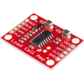
LOAD CELL AMP HX711
SPARKFUN¥3,500税込¥3,8501個33日以内出荷。Description。The SparkFun Load Cell Amplifier is a small breakout board for the HX711 IC that allows you to easily read load cells to measure weight. By connecting the amplifier to your microcontroller you will be able to read the changes in the resistance of the load cell, and with some calibration you'll be able to get very accurate weight measurements. This can be handy for creating your own industrial scale, process control or simple presence detection.。This version of the SparkFun Load Cell Amplifier features a few changes that you specifically asked for! We have separated the analog and digital supply, as well as added a 3.3uH inductor and a 0.1uF filter capacitor for digital supply. Need even more? Checkout the SparkFun Qwiic Scale. It has all the features of the HX711 but with additional library support, a true I2C interface, and no soldering required!。The HX711 uses a two-wire interface(Clock and Data)for communication. Any microcontroller's GPIO pins should work, and numerous libraries have been written, making it easy to read data from the HX711. Check the hookup guide below for more information.。Load cells use a four-wire Wheatstone bridge configuration to connect to the HX711. These are commonly colored RED, BLK, WHT, GRN and YLW. Each color corresponds to the conventional color coding of load cells:Red(Excitation+ or VCC)。Black(Excitation- or GND)。White(Amplifier-, Signal- or Output-)。Green(A+, S+ or O+)。Yellow(Shield)。The YLW pin acts as an optional input that is not hooked up to the strain gauge but is utilized to ground and shield against outside EMI(electromagnetic interference). Please keep in mind that some load cells might have slight variations in color coding.。Note:Special thanks to Bodge for supplying the Library for the HX711!。Get Started with the HX711 Load Cell Amplifier Guide。Features。Operation Voltage:2.7V--5V。Operation Current:< 1.5mA。Selectable 10SPS or 80SPS output data rate。Simultaneous 50 and 60Hz supply rejectionアズワン品番67-0362-17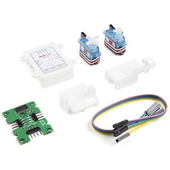
Arducam Upgraded Camera Pan Tilt Platform
SPARKFUN¥9,998税込¥10,9981個33日以内出荷Description。If you're looking for a sturdy pan-tilt mechanism for most of the cameras that are used with Arduino and Raspberry Pi but don't want the weight of metal, this is the rig for you. The Upgraded Camera Pan Tilt Platform from Arducam takes theアズワン品番67-0426-45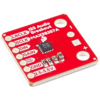
SparkFun I2S Audio Breakout - MAX98357A
SPARKFUN¥1,998税込¥2,1981個33日以内出荷Description。The SparkFun I2S Audio Breakout board uses the MAX98357A digital to analog converter(DAC), which converts I2S(not be confused with I2C)audio to an analog signal to drive speakers. The I2S Audio Breakout converts the digital audio signals using the I2S standard to an analog signal and amplifies the signal using a class D amplifier which can deliver up to 3.2W of power into a 4Ω load. The board can be configured to output only the left channel audio, right channel, or both.。The SparkFun I2S Audio Breakout board is fairly simple, requiring only a few pin connections to get it up and working. By default the board is configured in "mono" operation, meaning the left and right signals are combined together to drive a single speaker. If you want a separate speaker for the left and right audio channels you'll need to cut the mono jumper. In addition to being able to select the audio channel output, the gain can also be configured in a few ways. The gain of the amplifier can be configured from as low as +3dB to as high as +15dB. While the channel selection can be configured on board, the gain however is controlled externally using the gain pin. By default, the board is configured for +9dB, but can be easily changed!。Get Started with the SparkFun I2S Audio Breakout Guide。Features。Supply Voltage Range:2.5V - 5.5V.。Output Power:3.2W into 4Ω at 5V.。Output Channel Selection:Left, Right, or Left/2 + Right/2(Default).。Sample Rate:8kHz - 96kHz.。Sample Resolution:16/32 bit.。Quiescent Current:2.4mA.。Filterless Class D Outputs。No MCLK Required。Click and Pop Reduction。Short-Circuit and Thermal Protection.アズワン品番67-0422-64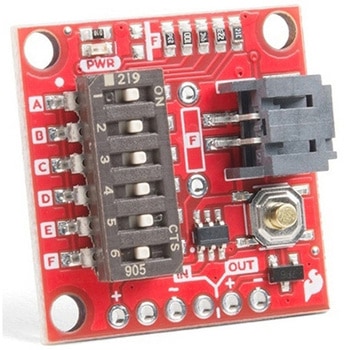
SparkFun Nano Power Timer - TPL5110
SPARKFUN¥2,398税込¥2,6381個33日以内出荷。Description。Sometimes we want our projects on, but sometimes we want to turn them off for a while to save power. The SparkFun Nano Power Timer will run while only consuming minimal power(approximately 35nA)and turn your project on after a set amount of time. When you are done polling your sensors, posting data to the web, writing to your logger, or planning world domination, your microcontroller can tell the Nano Power Timer to turn off the power. No more running your microcontroller all day when you only want to read the ambient temperature once per hour.。The TPL5110 delay is configured with the use of resistors. We've added a six-way DIP switch to select one of the five preinstalled resistors. The sixth switch is attached to a pad to add your own PTH(or SMD)resistor. The delays associated with the preinstalled headers are shown on the bottom of the board for quick setup. Additionally, you can select more than one switch to combine the resistors in parallel(up to 26 options not including the custom resistor), check out the hookup guide for a nice chart as to the total resistance and corresponding delay for each combination.。The Nano Power Timer can handle voltages between 1.8V and 5.5V as well as current up to 1.1A with times from 100ms to two hours(preconfigured settings range from 30s to 2h). You will find a button on the board which will allow you a quick override to the delay so you can turn your project on whenever you like.。Get Started with the SparkFun Nano Power Switch。Features。Supply Voltage:1.8V to 5.5V。Current consumption at 2.5V:35nA Typical(50nA Max)。Selectable Time intervals:100ms to 7200s(2 hours)。Timer Accuracy:1%アズワン品番67-0425-68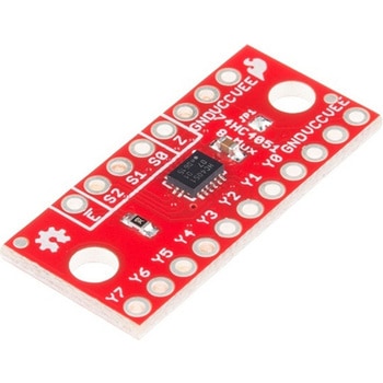
SparkFun Multiplexer Breakout - 8 Channel 74HC4051
SPARKFUN¥999税込¥1,0991個33日以内出荷Description。The SparkFun Multiplexer Breakout provides access to all pins and features of the 74HC4051, an 8-channel analog multiplexer/demultiplexer. The 74HC4051 allows you to turn four I/O pins into eight multifunctional, individually selectable signals, which can be used to do everything from driving eight LEDs to monitoring eight potentiometers.。The 74HC4051 can function as either a multiplexer or a demultiplexer, and it features eight channels of selectable inputs/outputs. The routing of common signal to independent I/O is set by digitally controlling three select lines, which can be set either high or low into one of eight binary combinations.。One half of the board breaks out the control signals(E, S0-S2)and common input/output(Z). The other side provides access to all eight independent I/O's(Y0-Y7). Both sides include supply and ground connections(VCC, VEE, GND).。Get Started with the 74HC4051 Breakout Guide。Features。Switches analog or digital signals。8 channels controlled by 3 select inputs。Wide voltage supply range:2 -- 10V。Bipolar supply support(e.g., ±5V)。Optional enable input。Breadboard compatible breakoutアズワン品番67-0419-95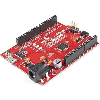
SparkFun RedBoard Qwiic
SPARKFUN¥6,998税込¥7,6981個33日以内出荷Description。At SparkFun we continually like to innovate, update, and improve even when it comes to our very own development boards. We have multiple versions of the SparkFun RedBoard in our catalog but none of them in an R3 form factor with a Qwiic conアズワン品番67-0422-71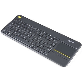
Logitech K400 Plus Wireless Touch Keyboard
SPARKFUN¥16,980税込¥18,6781個33日以内出荷Description。The Logitech K400 Plus Wireless Touch Keyboard is a compact keyboard with an integrated touchpad that puts all your controls in a single device. Enjoy your entertainment without the clutter of multiple devices. Comfortable, quiet keys and aアズワン品番67-0429-23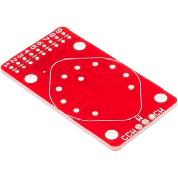
SparkFun Rotary Switch Potentiometer Breakout
SPARKFUN¥1,098税込¥1,2081個33日以内出荷Description。The SparkFun Rotary Switch Potentiometer Breakout is a small board the allows you to add resistors to a 10-position rotary switch, turning it into a potentiometer with 10 discrete steps. Multiple applications require potentiometers that areアズワン品番67-0419-84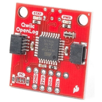
SparkFun Qwiic OpenLog
SPARKFUN¥6,498税込¥7,1481個33日以内出荷Description。The SparkFun Qwiic OpenLog is the smarter and better looking cousin to the extremely popular OpenLog but now we've ported the original serial based interface to I2C! Thanks to the added Qwiic connectors, you can daisy chain multiple I2C devアズワン品番67-0422-74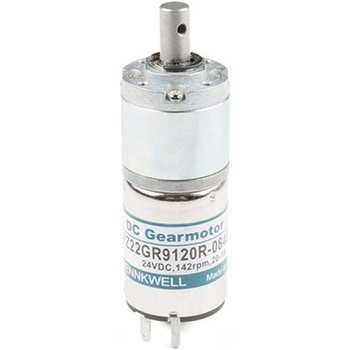
Planetary Gearmotor - 140RPM
SPARKFUN¥2,198税込¥2,4181個33日以内出荷Description。This is a simple ~140RPM(no load), DC planetary gearmotor. This motor is great for various applications such as robotics, electric locks, household automation, and small actuators.。The supply voltage range is 6VDC - 24VDC with the polariアズワン品番67-0426-32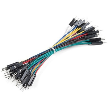
Jumper Wires Premium 4" M/M - 26 AWG 30 Pack
SPARKFUN¥879税込¥9671個33日以内出荷Description。These are 101mm long 26AWG jumpers with male connectors on both ends. Use these to jumper from any female header on any board to any other female header. Combine these with our female-to-female jumpers to create a male-to-female jumper. Multiple jumpers can be installed next to one another on a 0.1" header.。Comes as one pack of 30 jumpers with an assortment of colors.。Features。4" longアズワン品番67-0425-33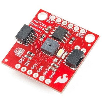
SparkFun Spectral Sensor Breakout - AS7263 NIR Qwiic
SPARKFUN¥9,998税込¥10,9981個33日以内出荷Description。The SparkFun AS7263 Near Infrared(NIR)Spectral Sensor Breakout brings spectroscopy to the palm of your hand, making it easier than ever to measure and characterize how different materials absorb and reflect different wavelengths of light. The AS7263 Breakout is unique in its ability to communicate by both an I2C interface and serial interface using AT commands. Hookup is easy, thanks to the Qwiic connectors attached to the board --- simply plug one end of the Qwiic cable into the breakout and the other into one of the Qwiic shields, then stack the board on a development board. You'll be ready to upload a sketch to start taking spectroscopy measurements in no time.。The AS7263 spectrometer detects wavelengths in the visible range at 610, 680, 730, 760, 810 and 860nm of light, each with 20nm of full-width half-max detection. The board also has multiple ways for you to illuminate objects that you will try to measure for a more accurate spectroscopy reading. There is an onboard LED that has been picked out specifically for this task, as well as two pins to solder your own LED into.。Note:The I2C address of the AS7263 is 0x49 and is hardware defined. A multiplexer/Mux is required to communicate to multiple AS7263 sensors on a single bus. If you need to use more than one AS7263 sensor consider using the Qwiic Mux Breakout.。The SparkFun Qwiic Connect System is an ecosystem of I2C sensors, actuators, shields and cables that make prototyping faster and less prone to error. All Qwiic-enabled boards use a common 1mm pitch, 4-pin JST connector. This reduces the amount of required PCB space, and polarized connections mean you can't hook it up wrong.。Get Started with the SparkFun AS726X Spectral Sensor Breakout Guide。Features。6 near-IR channels:610nm, 680nm, 730nm, 760nm, 810nm and 860nm, each with 20nm FWHM。NIR filter set realized by silicon interference filters。16-bit ADC with digital access。Programmable LED drivers。2.7V to 3.6V with I2C interface。2x Qwiic connectorsアズワン品番67-0426-70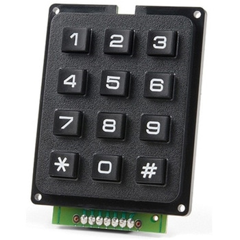
SparkFun Qwiic Keypad - 12 Button
SPARKFUN¥4,198税込¥4,6181個33日以内出荷Description。Keypads are very handy input devices, but who wants to tie up seven GPIO pins, wire up handful of pull-up resistors, and write firmware that wastes valuable processing time scanning the keys for inputs? The SparkFun Qwiic Keypad comes fully assembled and makes the development process for adding 12 button keypad easy. No voltage translation or figuring out which I2C pin is SDA or SCL, just plug and go! Utilizing our handy Qwiic system, no soldering is required to connect it to the rest of your system. However, we still have broken out 0.1"-spaced pins in case you prefer to use breadboard.。Each of the keypad's 12 buttons has been labeled 1, 2, 3, 4, 5, 6, 7, 8, 9, 0, *, and and has been formatted to into the same layout as telephone keypad with each keypress resistance ranging between 10 and 150 Ohms. The Qwiic Keypad reads and stores the last 15 button presses in First-In, First-Out(FIFO)stack, so you don't need to constantly poll the keypad from your microcontroller. This information, then, is accessible through the Qwiic interface. The SparkFun Qwiic Keypad even has software configurable I2C address so you can have multiple I2C devices on the same bus.。NOTE:The I2C address of the Qwiic Keypad is 0x4B and is jumper selectable to 0x4A(software-configurable to any address). multiplexer/Mux is required to communicate to multiple Qwiic Keypad sensors on single bus. If you need to use more than one Qwiic Keypad sensor consider using the Qwiic Mux Breakout.。The SparkFun Qwiic connect system is an ecosystem of I2C sensors, actuators, shields and cables that make prototyping faster and less prone to error. All Qwiic-enabled boards use common 1mm pitch, 4-pin JST connector. This reduces the amount of required PCB space, and polarized connections mean you can't hook it up wrong.。Get Started with the SparkFun Qwiic Keypad Hookup Guide。Features。Software Selectable Slave Address。Low Power ATtiny85 controller。Button Presses w/ Time Stamp。Default I2C Address:0x4B。2x Qwiic Connectorアズワン品番67-0421-41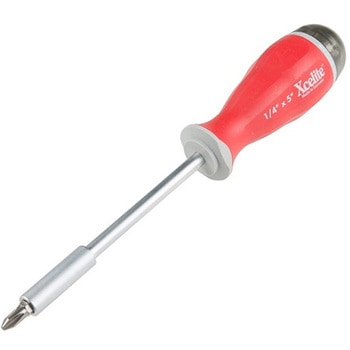
Xcelite 8-in-1 Screwdriver Set
SPARKFUN¥8,998税込¥9,8981個33日以内出荷Description。The Xcelite 8-in-1 Screwdriver Set provides eight high-quality bits in a single ergonomic tool. Each bit is easily accessible with a spring-loaded magnetic housing that holds the seven included bits you aren't currently using. Though the screwdriver set includes eight unique bits, the end of the shaft features a 0.25" hex driver that can fit most of your existing 1/4" bits. With a strong magnetic hold and no-roll handle design, this is one of the best all-in-one tools we have used!。The shaft of this multiple-tip driver is made from a chrome-molybdenum vanadium steel that makes for great durability and longevity.アズワン品番67-0428-23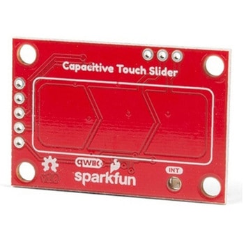
SparkFun Capacitive Touch Slider - CAP1203 Qwiic
SPARKFUN¥2,498税込¥2,7481個33日以内出荷。Description。Do you want to replace a slider or a button on your art project or science experiment with a more interesting interface? This Capacitive Touch Slider is a "Qwiic" and easy way to add capacitive touch to your next project. With the board's built in touch pads, you can immediately start playing with the touch capabilities as three unique touch inputs or as a slider. You can also enable a touch input to act as a power button, customize the sensitivity for your own touch pads, and play with the interrupt alert LED. Utilizing our Qwiic system, no soldering is required to connect it to the rest of your system. However, we have broken out 0.1"-spaced pins in case you prefer to use a breadboard or create your own touch pads.。On the front of the board, there is an arrow shape which contains three separate capacitive touch pads. We also broke out the capacitive touch sensor lines as plated through-holes on the top of the board. You can use these pins to connect to your own capacitive touch pads. The CS1 pin connects to the left pad, the CS2 pin connects to the middle pad, and the CS3 pin connects to the right pad.。NOTE:The I2C address of the CAP1203 is 0x28 and is hardware defined. A multiplexer/Mux is required to communicate to multiple CAP1203 sensors on a single bus. If you need to use more than one CAP1203 sensor consider using the Qwiic Mux Breakout.。The SparkFun Qwiic connect system is an ecosystem of I2C sensors, actuators, shields and cables that make prototyping faster and less prone to error. All Qwiic-enabled boards use a common 1mm pitch, 4-pin JST connector. This reduces the amount of required PCB space, and polarized connections mean you can't hook it up wrong.。Get Started with the SparkFun Capacitive Touch Slider Guide。Features。Capacitive Touch。3 unique capacitive touch inputs。Features。Emulated slider。Power button setting。Programmable sensitivity。Automatic recalibration。I2C Address:0x28。Qwiic Enabled。Operating Range。Supply Voltage:3.3V - 5Vアズワン品番67-0427-06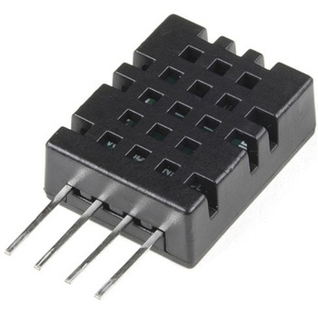
Humidity and Temperature Sensor - DHT20
SPARKFUN¥2,698税込¥2,9681個33日以内出荷Description。The DHT20 is a low cost humidity and temperature sensor with a I2C digital output protocol. It can be applied to HVAC, dehumidifier, automatic control, data loggers, weather stations, and many other projects. The sensor is calibrated and doesn't require extra components so you can get right to measuring relative humidity and temperature.。Features。Supply Voltage:2.2-5.5V。Communication:Standard I2C Protocol。Humidity from 0-100% RH。Typical accuracy:RH:±3%, T:±0.5℃。-40 - 80 degrees C temperature rangeアズワン品番67-0427-56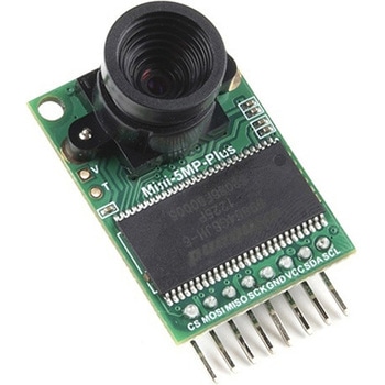
Arducam 5MP Plus OV5642 Mini Camera Module
SPARKFUN¥23,980税込¥26,3781個33日以内出荷Description。The Arducam 5MP Plus OV5642 Mini provides an easy to use camera solution for those working with low-cost microcontrollers such as those used with Arduino and the RP2040 from Raspberry Pi. It's a general purpose 5MP camera module that's SPI enabled reducing the complexity of controlling the camera. It's a step up in performance from it's predecessor, the Arducam-M-5MP. The most impressive aspect being that it's possible to control more than one of these from the same microcontroller. It features a M12 mount or CS-Mount lens holder with the ability to change lenses. Best of all, there's code libraries for Arduino, STM32, Chipkit, Raspberry Pi, and BeagleBone Black.。The Arducam 5MP Plus OV5642 Mini supports JPEG compression mode, single and multiple shoot mode, short movie recording, one-time capture multiple read operation, burst read operation, and low power mode.。Features。Power supply 3.3V~5V。Active array size:2592×1944。SPI speed:Max 8MHz。Shutter:rolling shutter。Frame buffer:8MByte。Pixel Size:1.4μm×1.4μm。Default M12 Lens:55°。Resolution support:5MP, 1080p, 720p, VGA, QVGA。Format support:RAW, YUV, RGB, JPEG。Size:34×24 mm。Weight:20g。Temperature Range:-10℃~+55℃。Lens Specification:sensor size:1/4″; EFL:4.9mm; F/N:2.2; BFL:1.2mm; HFOV:60 degree(SKU:U6067)アズワン品番67-0423-65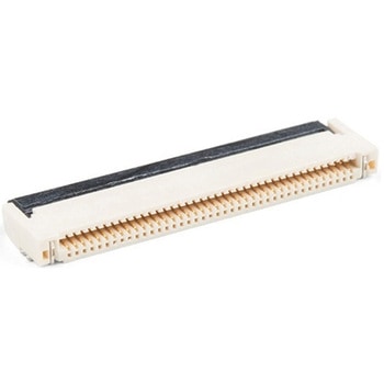
40 Pin 0.5mm FPC, SMD, Both Sides
SPARKFUN¥219税込¥2411個33日以内出荷。Description。This is a 40-pin surface mount FPC(Flat Printed Circuit)connector. Nothing too fancy here, except that it can be plugged in either way - contacts up or down. This is useful for manufacturers because they only have to keep one item in stock. It is useful for consumers because they can use one connector to fit in multiple orientations.。This product fits the 1.77 TFT LCD Display 160x128 RGB - 3 Wire and thanks to its dual-sided nature you can use it upside down or all-around.。TFT Display Not Included。This product mates and is pictured with the 1.8in. TFT LCD 160x128 RGB。Features。40 pins。0.5mm pitch。Top/bottom side contacts(both)。Lockingアズワン品番67-0425-59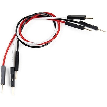
Jumper Wires Premium 6in. M/M - 3 Pack Red, Black, and White
SPARKFUN¥519税込¥5711個33日以内出荷Description。Jumper wires are awesome. Just a little bit of stranded core wire with a nice solid pin connector on either end. They have the flexibility of stranded wire but will fit directly into breadboards and female pin headers. These are six inch long, 26 AWG jumper wires with breadboard-friendly male connectors on both ends. Combine these with our female to female jumpers to create a male to female jumper. Multiple jumpers can be connected next to one another on a 0.1in header.。These jumper wires can be used for pretty much everything! They work great with breadboards, Arduinos, and really any 0.1in pitch prototyping board.。Features。6in. long。26 AWGアズワン品番67-0426-17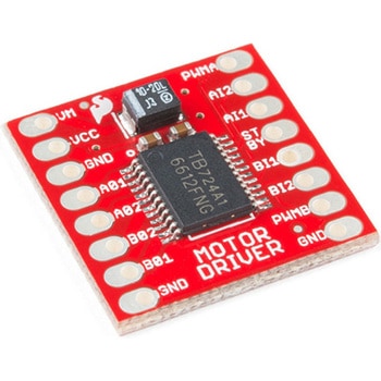
モータードライバ
SPARKFUN¥4,798税込¥5,2781個33日以内出荷Description。The TB6612FNG Motor Driver can control up to two DC motors at a constant current of 1.2A(3.2A peak). Two input signals(IN1 and IN2)can be used to control the motor in one of four function modes:CW, CCW, short-brake and stop. The two motor outputs(A and B)can be separately controlled, and the speed of each motor is controlled via a PWM input signal with a frequency up to 100kHz. The STBY pin should be pulled high to take the motor out of standby mode.。Logic supply voltage(VCC)can be in the range of 2.7--5.5VDC, while the motor supply(VM)is limited to a maximum voltage of 15VDC. The output current is rated up to 1.2A per channel(or up to 3.2A for a short, single pulse).。This little board comes with all components installed as shown. Decoupling capacitors are included on both supply lines. All pins of the TB6612FNG are broken out to two 0.1" pitch headers; the pins are arranged such that input pins are on one side and output pins are on the other.。Note:。If you are looking for the SparkFun Motor Driver with headers, it can be found here or in the。Similar Products。below.。Get Started With the Motor Driver Hookup Guide。Features。Power supply voltage:VM = 15V max, VCC = 2.7--5.5V。Output current:Iout = 1.2A(average)/ 3.2A(peak)。Standby control to save power。CW/CCW/short-brake/stop motor control modes。Built-in thermal shutdown circuit and low-voltage detecting circuit。All pins of the TB6612FNG broken out to 0.1" spaced pins。Filtering capacitors on both supply linesアズワン品番67-0395-99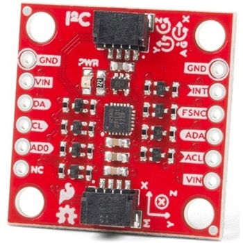
SparkFun 9DoF IMU Breakout - ICM-20948 Qwiic
SPARKFUN¥7,298税込¥8,0281個33日以内出荷。Description。The SparkFun 9DoF IMU Breakout incorporates all the amazing features of Invensense's ICM-20948 into a Qwiic-enabled breakout board complete with a logic shifter and broken out GPIO pins for all your motion sensing needs. The ICM-20948 itself is an extremely low powered, I2C and SPI enabled 9-axis motion tracking device that is ideally suited for smartphones, tablets, wearable sensors, and IoT applications. Utilizing our handy Qwiic system, no soldering is required to connect it to the rest of your system. However, we still have broken out 0.1"-spaced pins in case you prefer to use a breadboard.。In addition to the 3-Axis Gyroscope with four selectable ranges, 3-Axis Accelerometer, again with four selectable ranges, and 3-axis magnetometer with an FSR to ±4900μT, the ICM-20948 also includes a Digital Motion Processor that offloads the computation of motion sensing algorithms from the detectors, allowing optimal performance of the sensors. We've also broken out all the ICM-20948 pin functionality to GPIO and labeled them I2C on the front, SPI on the back for ease of identification.。Note:The I2C address of the ICM-20948 is 0x69 and is jumper selectable to 0x68. A multiplexer/Mux is required to communicate to multiple ICM-20948 sensors on a single bus. If you need to use more than one ICM-20948 sensor consider using the Qwiic Mux Breakout.。The SparkFun Qwiic Connect System is an ecosystem of I2C sensors, actuators, shields and cables that make prototyping faster and less prone to error. All Qwiic-enabled boards use a common 1mm pitch, 4-pin JST connector. This reduces the amount of required PCB space, and polarized connections mean you can't hook it up wrong.。Need a custom board? This component can be found in SparkFun's A La Carte board builder. You can have a custom design fabricated with this component - and your choice of hundreds of other sensors, actuators and wireless devices - delivered to you in just a few weeks.。Get Started with the SparkFun ICM-20948 9DoF IMU Guide。Features。1.95 V to 3.6 V supply voltage。Triple-axis MEMS gyroscope with user-programmable full-scale range of ±250 dps, ±500 dps, ±1000 dps, and ±2000 dps。Triple-axis MEMS accelerometer with programmable full scale range of ±2g, ±4g, ±8g, and ±16g。Triple-axis silicon monolithic Hall-effect magnetic sensor with full scale measurement range to ±4900 μT。I2C at up to 100 kHz(standard-mode)or up to 400 kHz(fast-mode)or SPI at up to 7 MHz for communicationwith registers。On-board digital motion processor(DMP)。Digital-output temperature sensor。2x Qwiic Connection Ports。I2C Address:0x69(0x68 with Jumper)。。Documents。Schematic。Eagle Files。Hookup Guide。Datasheet(ICM-20948)。Arduino Library。Python Support(Qwiic_Py)。GitHub Hardware Repoアズワン品番67-0427-05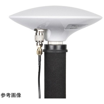
GNSS Multi-Band L1/L2 Surveying Antenna TNC - TOP106
SPARKFUN¥68,980税込¥75,8781個33日以内出荷Description。The TOP106 from TOPGNSS is a GNSS/GPS antenna capable of receiving the L1/L2 bands for GPS, GLONASS, Galileo, and BeiDou constellations. These 'UFO' antennas have incredible performance for the money. The antenna has a built in ground planアズワン品番67-0423-91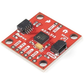
SparkFun Triple Axis Digital Accelerometer Breakout - ADXL313 Qwiic
SPARKFUN¥6,698税込¥7,3681個33日以内出荷Description。The SparkFun ADXL313 Breakout is a low power, high resolution(up to 13-bits)3-axis accelerometer for measurement up to ±4g. This breakout measures the static acceleration of gravity in tilt-sensing applications, as well as dynamic accelアズワン品番67-0427-42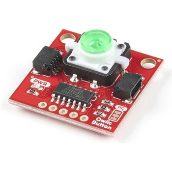
SparkFun Qwiic Button - Green LED
SPARKFUN¥1,698税込¥1,8681個33日以内出荷Description。Buttons are an easy and tactile way to interface with your project, but why would you want to deal with debouncing, polling, and wiring up pull-up resistors? The Qwiic Button with built-in green LED simplifies all of those nasty worries away into an easy to use I2C device! Utilizing our Qwiic Connect System, using the button is as simple as connecting cable and loading up some pre-written code!。If you need multiple buttons for your project, fear not! Each button has configurable I2C address, so you can daisy-chain multiple buttons over Qwiic and still address each one individually. We've got an example in our Arduino library that provides super-easy way to configure your Qwiic Button to whatever I2C address you desire. You can download the library through the Arduino library manager by searching 'SparkFun Qwiic Button' or you can get the GitHub repo as .zip file and install the library from there.。In addition to handling blinking and debouncing, the Qwiic Button has configurable interrupts that can be configured to activate upon button press or click. We've also taken the liberty of implementing FIFO queue onboard the Qwiic Button where it keeps an internal record of when the button was pressed. This means that code on your microcontroller need not waste valuable processing time checking the status of the button but instead can run small function whenever the button is pressed or clicked! For more information on interrupts check out our guide here!。The SparkFun Qwiic Connect System is an ecosystem of I2C sensors, actuators, shields and cables that make prototyping faster and less prone to error. All Qwiic-enabled boards use common 1mm pitch, 4-pin JST connector. This reduces the amount of required PCB space, and polarized connections mean you can't hook it up wrong.。Get Started with the SparkFun Qwiic Button Guide。Features。12mm Green LED Button rated for 50mA。Built in LED can be configured for your desired level of blinkiness!。Each button has configurable I2C address。Configurable interrupts check out our guide here!。FIFO queue。Don't like the color green? Check out the SparkFun Qwiic Button Breakout and add another colored button!。Red LED Tactile Button。Blue LED Tactile Button。Green LED Tactile Button。White LED Tactile Buttonアズワン品番67-0420-14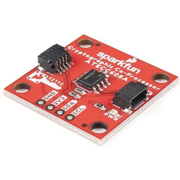
SparkFun Cryptographic Co-Processor Breakout - ATECC608A Qwiic
SPARKFUN¥1,498税込¥1,6481個33日以内出荷。Description。Product Restrictions:To access certain features of the ATECC608A, users will need to contact Microchip and sign an NDA contract to obtain the complete datasheet. Due to the required NDA - technical support, an Arduino library, and hookup guide are not provided for users on this product.。The SparkFun ATECC608A Cryptographic Co-processor Breakout allows you to add strong security to your IoT node, edge device, or embedded system. This includes。a。symmetric。authentication,。symmetric。AES-128 encryption/decryption, and much more. As stated above, the ATECC608A has limited Arduino support and the complete datasheet is under NDA with Microchip.。This breakout board includes two Qwiic ports for plug and play functionality. Utilizing our handy Qwiic system, no soldering is required to connect it to the rest of your system. However, we still have broken out 0.1"-spaced pins in case you prefer to use a breadboard. The ATECC608A chip is capable of many cryptographic processes, including, but not limited to:Creating and securely storing unique asymmetric key pairs based on Elliptic Curve Cryptography(FIPS186-3).。AES-128:Encrypt/Decrypt, Galois Field Multiply for GCM。Creating and verifying 64-byte digital signatures(from 32-bytes of message data).。Creating a shared secret key on a public channel via Elliptic Curve Diffie-Hellman Algorithm.。SHA-256 HMAC Hash including off-chip context save/restore。Internal high quality FIPS random number generator.。Embedded in the chip is a 10Kb EEPROM array that can be used for storing keys, certificates, data, consumption logging, and security configurations. Access to the sections of memory can then be restricted and the configuration locked to prevent changes. Each ATECC608A Breakout ships with a guaranteed unique 72-bit serial number and includes several security features to prevent physical attacks on the device itself, or logical attacks on the data transmitted between the device.。A summary datasheet for the ATECC608A is available here. The full datasheet is under NDA with Microchip. You will need to contact them for access to the entire datasheet. Meanwhile, the ArduinoATECCX08 Library currently only supports the ATECC608A with SAMD21 Arduino boards.。We do have much more support for the ATECC508A version of this chip. Please check out our ATECC508A Hookup Guide and Arduino Library(which includes six examples). This will get you familiar with the basics of elliptic curve cryptography and signing/verifying data with the ATECC508A version of the chip.。Note:The I2C address of the ATECC608A is 0x60 and is software-configurable to any address. A multiplexer/Mux is required to communicate to multiple ATECC608A sensors at the default address when on a single bus. If you need to use more than one ATECC608A sensor at the default address, consider using the Qwiic Mux Breakout.。Note:The ATECC608A can be only configured once before it is。PERMANENTLY。locked。. It is advisable that users purchase multiple boards in order to use other configurations and explore the advanced functions of the ATECC608A.。Additionally, this board。IS。capable of encrypting and decrypting data. However, to access these additional features, you will need to contact Microchip and sign an NDA contract to obtain the complete datasheet.。It is recommended that an SparkFun RedBoard Turbo - SAMD21 Development Board is used with this product due to the buffer size required on the I2C bus.。The SparkFun Qwiic Connect System is an ecosystem of I2C sensors, actuators, shields and cables that make prototyping faster and less prone to error. All Qwiic-enabled boards use a common 1mm pitch, 4-pin JST connector. This reduces the amount of required PCB space, and polarized connections mean you can't hook it up wrong.。。Features。Operating Voltage:2.0V-5.5V(。Default on Qwiic System:3.3V。)。Active Current Draw(for ATECC608A):16 mA。Sleep Current(for ATECC608A):<150 nA。Guaranteed Unique 72-bit Serial Number。10 Kb EEPROM Memory for Keys, Certificates, and Data。Storage for up to 16 Keys。256-bit Key Length。Internal High-Quality FIPS Random Number Generator(RNG)。Configurable I2C Address(7-bit):0x60(。Default。)アズワン品番67-0423-59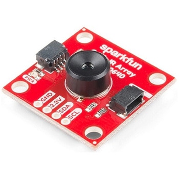
SparkFun IR Array Breakout - 110 Degree FOV, MLX90640 Qwiic
SPARKFUN¥22,980税込¥25,2781個33日以内出荷Description。It's time to say hip hip array for this IR Breakout! The MLX90640 SparkFun IR Array Breakout is equipped with a 32x24 array of thermopile sensors creating, in essence, a low resolution thermal imaging camera. With this breakout you can detect surface temperatures from many feet away with an accuracy of ±1.5℃(best case). To make it even easier to get your low-resolution infrared image, all communication is enacted exclusively via I2C, utilizing our handy Qwiic system. However, we still have broken out 0.1"-spaced pins in case you prefer to use a breadboard.。This specific IR Array Breakout features a 110°x75° field of view with a temperature measurement range of -40℃-300℃. The MLX90640 IR Array has pull up resistors attached to the I2C bus; both can be removed by cutting the traces on the corresponding jumpers on the back of the board. Please be aware that the MLX90640 requires complex calculations by the host platform so a regular Arduino Uno(or equivalent)doesn't have enough RAM or flash to complete the complex computations required to turn the raw pixel data into temperature data. You will need a microcontroller with 20,000 bytes or more of RAM. To achieve this, we recommend a Teensy 3.1 or above.。Note:The I2C address of the MLX90640 is 0x33 and is hardware defined. A multiplexer/Mux is required to communicate to multiple MLX90640 sensors on a single bus. If you need to use more than one MLX90640 sensor consider using the Qwiic Mux Breakout.。The SparkFun Qwiic connect system is an ecosystem of I2C sensors, actuators, shields and cables that make prototyping faster and less prone to error. All Qwiic-enabled boards use a common 1mm pitch, 4-pin JST connector. This reduces the amount of required PCB space, and polarized connections mean you can't hook it up wrong.。Get Started with the SparkFun IR Array Breakout Guide。Features。Operating Voltage:3V-3.6V。Current Consumption:~18mA。Field of View:110°x75°。Measurement Range:-40℃-300℃。Resolution:±1.5℃。Refresh Rate:0.5Hz-64Hz。I2C Address:0x33。2x Qwiic Connection Portsアズワン品番67-0426-87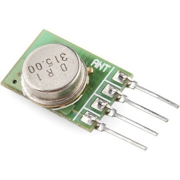
RF Link Transmitter - 315MHz
SPARKFUN¥1,698税込¥1,8681個33日以内出荷Description。These wireless transmitters work with our 315MHz receivers. They can easily fit into a breadboard and work well with microcontrollers to create a very simple wireless data link. Since these are only transmitters, they will only work communicating data one-way, you would need two pairs(of different frequencies)to act as a transmitter/receiver pair.。Note:These modules are indiscriminate and will receive a fair amount of noise. Both the transmitter and receiver work at common frequencies and don't have IDs. Therefore, a method of filtering this noise and pairing transmitter and receiver will be necessary. The example code below shows such an example for basic operation. Please refer to the example code and links below for ways to accomplish a robust wireless data link.。Features。315MHz。500ft range(given perfect conditions)。4800bps data rate。5V supply voltageアズワン品番67-0430-46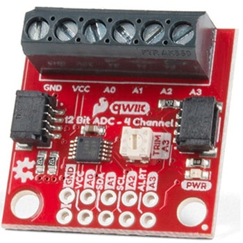
QWIIC 12BIT 4CHANNEL ADS1015
SPARKFUN¥5,498税込¥6,0481個33日以内出荷Description。A lot of the time you just need to add more analog inputs to solve a problem. It happens. The SparkFun Qwiic 12 Bit ADC can provide four channels of I2C controlled ADC input to your Qwiic enabled project. These channels can be used as single-ended inputs, or in pairs for differential inputs. What makes this even more powerful is that it has a programmable gain amplifier that lets you "zoom in" on a very small change in analog voltage(but will still effect your input range and resolution). Utilizing our handy Qwiic system, no soldering is required to connect it to the rest of your system. However, we still have broken out 0.1"-spaced pins in case you prefer to use a breadboard.。The ADS1015 uses its own internal voltage reference for measurements, but a ground and 3.3V reference are also available on the pin outs for users. This ADC board includes screw pin terminals on the four channels of input, allowing for solderless connection to voltage sources in your setup. It also has an address jumper that lets you choose one of four unique addresses(0x48, 0x49, 0x4A, 0x4B). With this, you can connect up to four of these on the same I2C bus and have sixteen channels of ADC. The maximum resolution of the converter is 12-bits in differential mode and 11-bits for single-ended inputs. Step sizes range from 125μV per count to 3mV per count depending on the full-scale range(FSR)setting.。We have included an onboard 10K trimpot connected to channel A3. This is handy for initial setup testing and can be used as a simple variable input to your project. But don't worry, we added an isolation jumper so you can use channel A3 however you'd like.。Note:The I2C address of the ADS1015 is 0x48 and is jumper selectable to 0x49, 0x4A, 0x4B. A multiplexer/Mux is required to communicate to multiple ADS1015 sensors on a single bus. If you need to use more than one ADS1015 sensor consider using the Qwiic Mux Breakout.。The SparkFun Qwiic connect system is an ecosystem of I2C sensors, actuators, shields and cables that make prototyping faster and less prone to error. All Qwiic-enabled boards use a common 1mm pitch, 4-pin JST connector. This reduces the amount of required PCB space, and polarized connections mean you can't hook it up wrong.。Get Started with the SparkFun Qwiic 12-Bit ADC Hookup Guide。Features。ADS1015。Operating Voltage(VDD):2.0V-5.5V。(Note:When powering with a Qwiic cable, the input range is only 3.3v)。Operating Temperature:-40℃ to 125℃。Operation Modes:Single-Shot, Continuous-Conversion(Default), and Duty Cycling。Analog Inputs:Measurement Type:Single-Ended(Default)。Input Voltage Range:GND to VDD。Full Scale Range(FSR):±.256V to ±6.114V(Default:2.048V)。Resolution:12-bit(Differential)or 11-bit(Single-Ended)。LSB size:0.125mV - 3mV(Default:1 mV)。Sample Rate:128 Hz to 3.3 kHz(Default:1600SPS)。Current Consumption(Typical):150μA-200μA。I2C Address:0x48(Default), 0x49, 0x4A, or 0x4B。Screw pin terminals for solderless connection to voltage sources。Four unique I2C addresses:0x48。0x49。0x4A。0x4B。2x Qwiic connection ports。Onboard 10K trimpotアズワン品番67-0360-13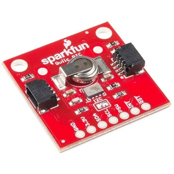
SparkFun Real Time Clock Module - RV-1805 Qwiic
SPARKFUN¥7,798税込¥8,5781個33日以内出荷Description。Get with the times, already! This SparkFun Real Time Clock(RTC)Module is a Qwiic-enabled breakout board for the RV-1805 chipset. The RTC is ultra-low power(running at only about 22nA in its lowest power setting)so it can use a supercapacitor for backup power instead of a normal battery. This means you get plenty of charge and discharge cycles without any degradation to the "battery." To make it even easier to get your readings, all communication is enacted exclusively via I2C, utilizing our handy Qwiic system so no soldering is required to connect it to the rest of your system. However, we still have broken out 0.1"-spaced pins in case you prefer to use a breadboard.。This RTC module's built in RV-1805 has not one, but two internal oscillators:a 32.768kHz tuning fork crystal and a low power RC based oscillator and can automatically switch between the two using the more precise crystal to correct the RC oscillator every few minutes. This feature allows the module to maintain a very accurate date and time with the worst case being +/- about three minutes over a year. The RV-1805 also has a built in trickle charger so as soon as the RTC is connected to power the it will be fully charged in under 10 minutes and has the ability to switch power to other systems allowing it to directly turn on or off a power hungry device such as a microcontroller or RF engine.。There is also the option to add a battery to the board if the supercapacitor just isn't going keep your project powered long enough(keep in mind, the supercap can hypothetically make the board keep time for around 35 days), you can solder on an external battery. That means you can let board sit with no power or connection to the outside world and the current hour/minute/second/date will be maintained.。Note:。The I2C address of the RV-1805 is 0x69 and is hardware defined. A multiplexer/Mux is required to communicate to multiple RV-1805 sensors on a single bus. If you need to use more than one RV-1805 sensor consider using the Qwiic Mux Breakout.。The SparkFun Qwiic connect system is an ecosystem of I2C sensors, actuators, shields and cables that make prototyping faster and less prone to error. All Qwiic-enabled boards use a common 1mm pitch, 4-pin JST connector. This reduces the amount of required PCB space, and polarized connections mean you can't hook it up wrong.。Get Started with the RV-1805 Real Time Clock Module Guide。Features。Operating Voltage(Startup):1.6V - 3.6V。Operating Voltage(Timekeeping):1.5V - 3.6V。Operating Temperature:-40℃ - 85℃。Time Accuracy:±2.0 ppm。Current Consumption:22nA(Typ.)。I2C Address:0xD2。Supercapacitor for Backup Power。2x Internal Oscillators。2x Qwiic Connectorsアズワン品番67-0420-02
Elektor MIT App Inventor Bundle
SPARKFUN¥25,980税込¥28,5781個33日以内出荷Description。The Elektor MIT App Inventor Bundle is a kit built to help learn about developing apps for Android compatible mobile devices using the MIT App Inventor online development environment. MIT App Inventor projects can be in either standalone mode or use an external processor. In standalone mode, the developed application runs only on the mobile device(e.g. Android). In external processor-based applications, the mobile device communicates with an external microcontroller-based processor, such as Raspberry Pi, Arduino, ESP8266, ESP32, etc.。The kit comes with a book and a selection of parts that correspond with a number of projects. Check out the features and Includes tab for more information.。Features。Projects Include:Using the text-to-speech component。Intonating a received SMS message。Sending SMS messages。Making telephone calls using a contacts list。Using the GPS and Pin-pointing our location on a map。Speech recognition and speech translation to another language。Controlling multiple relays by speech commands。Projects for the Raspberry Pi, ESP32 and Arduino using Bluetooth and Wi-Fi。MIT APP Inventor and Node-RED projects for the Raspberry Piアズワン品番67-0424-73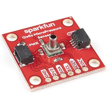
SparkFun Qwiic MicroPressure Sensor
SPARKFUN¥24,980税込¥27,4781個33日以内出荷Description。The SparkFun Qwiic MicroPressure Sensor is a miniature breakout equipped with Honeywell's 25psi piezoresistive silicon pressure sensor. This MicroPressure Sensor offers a calibrated and compensated pressure sensing range of 60mbar to 2.5bar, easy to read 24 bit digital I2C output, and can be calibrated and compensated over a specific temperature range for sensor offset, sensitivity, temperature effects, and non-linearity using an on-board Application Specific Integrated Circuit(ASIC). With its ultra-low power consumption and Qwiic ports, you've got yourself a power packed little sensor!。Each Qwiic MicroPressure Sensor has a calibrated pressure sensing range from 1-25psi and a power consumption rate as low as 0.01mW typ. average power, 1Hz measurement frequency for ultimate portability. Used in multiple medical(blood pressure monitoring, negative pressure wound therapy), industrial(air braking systems, gas and water meters), and consumer uses(coffee machines, humidifiers, air beds, washing machines, dishwashers), the SparkFun Qwiic MicroPressure Sensor is a great addition to the SparkFun Qwiic ecosystem!。The SparkFun Qwiic Connect System is an ecosystem of I2C sensors, actuators, shields and cables that make prototyping faster and less prone to error. All Qwiic-enabled boards use a common 1mm pitch, 4-pin JST connector. This reduces the amount of required PCB space, and polarized connections mean you can't hook it up wrong.。Get Started with the SparkFun Qwiic MicroPressure Hookup Guide。Features。Pressure Type:Absolute。Operating Pressure:25psi(172.37kPa)。I2C Address:0x18。Accuracy:±0.25%。Voltage - Supply:1.8V-3.6V。Port Size:Male - 0.1"(2.5mm)Tube。Port Style:Barbless。Maximum Pressure:60psi(413.69kPa)。Compatible with a variety of liquid media。2x Qwiic Connectorsアズワン品番67-0427-25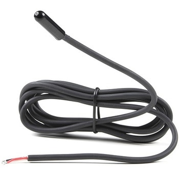
Temperature Sensor - High Temperature, Waterproof DS18B20
SPARKFUN¥3,698税込¥4,0681個欠品中Description。This sealed digital temperature probe lets you precisely measure temperatures in wet environments with a simple 1-Wire interface. The DS18B20 provides 9 to 12-bit(configurable)temperature readings over a 1-Wire interface, so that only one wire(and ground)needs to be connected from a central microprocessor. Power for reading, writing, and performing temperature conversions can be derived from the data line itself with no need for an external power source.。Because each DS18B20 contains a unique silicon serial number, multiple DS18B20s can exist on the same 1-Wire bus. This allows for placing temperature sensors in many different places. Applications where this feature is useful include HVAC environmental controls, sensing temperatures inside buildings, equipment or machinery, and process monitoring and control.。Note:The pinout for this sensor is as follows:RED=Vcc BLACK=GND WHITE=SIG。Features。3.0-5.5V input voltage。-55℃ to +125℃ temperature range。±0.5℃ accuracy from -10℃ to +85℃。Waterproof。1 Wire interface。Probe is 7mm in diameter and roughly 26mm long. Overall length(including wire)is 6 feet.。Thermometer resolution is programmable from 9 to 12 bits.。Electrical performance:no flicker or breakdown within AC 1200V/1S ,within DC 500V theinsulation resistance shall be greater than 100MΩアズワン品番67-0427-57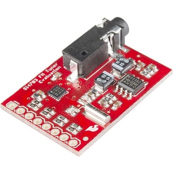
SparkFun FM Tuner Evaluation Board - Si4703
SPARKFUN¥7,298税込¥8,0281個33日以内出荷Description。This is an evaluation board for the Silicon Laboratories Si4703 FM tuner chip. Beyond enabling you to tune in to FM radio stations, the Si4703 is also capable of detecting and processing both Radio Data Service(RDS)and Radio Broadcast Data Service(RBDS)information. The Si4703 even does a very good job of filtering and carrier detection. It also enables data such as the station ID and song name to be displayed to the user.。Using this board, you will be able to pick up multiple stations just as well as with a standard FM radio. The board breaks out all major pins and makes it easy to incorporate this great chip into your next radio project. The power bus, the 3.3V and GND pins are broken out For communication. The breakout provides access to SDIO and SCLK for I2C communication while RST can be used for easy resetting. The SEN pin enables the user to change the mode of functionality of the IC. The last two pins broken out are GPIO1 and GPIO2 which can be used as general input/output pins, but also can be used for things like the RDS ready, seeking or tuning functions.。Keep in mind, by plugging headphones into the 3.5mm audio jack, you effectively use the cable in your headphones as an antenna! Therefore, this board does not require an external antenna if using headphones or a 3.5mm audio cable longer than 3 feet.アズワン品番67-0429-34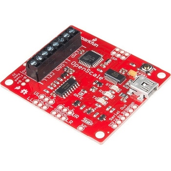
SparkFun OpenScale
SPARKFUN¥11,980税込¥13,1781個33日以内出荷Description。The SparkFun OpenScale is a simple-to-use, open source solution for measuring weight and temperature. It has the ability to read multiple types of load cells and offers a simple-to-use serial menu to configure calibration value, sample rate, time stamp and units of precision.。Simply attach a four-wire or five-wire load cell of any capacity, plug the OpenScale into a USB port, open a terminal window at 9,600bps, and you'll immediately see mass readings. The SparkFun OpenScale will enable you to turn a load cell or four load sensors in a Wheatstone bridge configuration into the DIY weigh scale for your application.。The OpenScale was designed for projects and applications where the load was static(like the beehive in front of SparkFun HQ)or where constant readings are needed without user intervention(for example, on a conveyor belt system). A load cell with an equipped OpenScale can remain in place for months without needing user interaction!。On board the SparkFun OpenScale is the ATmega328P microcontroller, for addressing your communications needs and transferring your data to a serial terminal or to a data logger such as the OpenLog, an FT231 with mini USB, for USB to serial connection; the HX711, a 24-bit ADC for weigh scales; and the TMP102, for recording the ambient temperature of your system. The OpenScale communicates at a TTL level of 9,600bps 8-N-1 by default and possesses a baud rate configurable from 1,200bps to 1,000,000bps.。Get Started with the OpenScale Guide。Features。Operating Voltage:5V。Operating Ampage:80-100mA。Power Cycling above 500ms。Selectable 10SPS or 80SPS Output Data Rate。Local External Temperature Sensors。Fixed Adjustable Gainアズワン品番67-0426-48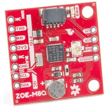
SparkFun GPS Breakout - ZOE-M8Q Qwiic
SPARKFUN¥14,980税込¥16,4781個33日以内出荷Description。The SparkFun ZOE-M8Q GPS Breakout is a high accuracy, miniaturized, GPS board that is perfect for applications that don't possess a lot of space. The on-board ZOE-M8Q is a 72-channel GNSS receiver, meaning it can receive signals from the GPS, GLONASS, BeiDou, and Galileo constellations. This increases precision and decreases lock time and thanks to the onboard rechargable battery you'll have backup power enabling the GPS to get a hot lock within seconds! Additionally, this u-blox receiver supports I2C(u-blox calls this Display Data Channel)which made it perfect for the Qwiic compatibility so we don't have to use up our precious UART ports. Utilizing our handy Qwiic system, no soldering is required to connect it to the rest of your system. However, we still have broken out 0.1"-spaced pins in case you prefer to use a breadboard.。U-blox based GPS products are configurable using the popular, but dense, windows program called u-center. Plenty of different functions can be configured on the ZOE-M8Q:baud rates, update rates, geofencing, spoofing detection, external interrupts, SBAS/D-GPS, etc. All of this can be done within the SparkFun Arduino Library. We've also made sure to configure the UART pin grouping on the breakout to an industry standard to insure that it easily connects to a Serial Basic.。The SparkFun ZOE-M8Q GPS Breakout is also equipped with an on-board rechargeable battery that provides power to the RTC on the ZOE-M8Q. This reduces the time-to-first fix from a cold start(~30s)to a hot start(~1s). The battery will maintain RTC and GNSS orbit data without being connected to power for up to five hours. Since the ZOE-M8Q is a tiny GPS receiver and to minimize its footprint, we've added a U.FL connector to allow the use of both large standard ceramic antennas as well as very small chip scale antennas.。Note:The I2C address of the ZOE-M8Q is 0x42 and is software configurable. A multiplexer/Mux is required to communicate to multiple ZOE-M8Q sensors on a single bus. If you need to use more than one ZOE-M8Q sensor consider using the Qwiic Mux Breakout.。The SparkFun Qwiic Connect System is an ecosystem of I2C sensors, actuators, shields and cables that make prototyping faster and less prone to error. All Qwiic-enabled boards use a common 1mm pitch, 4-pin JST connector. This reduces the amount of required PCB space, and polarized connections mean you can't hook it up wrong.。The ZOE-M8Q GPS Breakout can also be automatically detected, scanned, configured, and logged using the OpenLog Artemis datalogger system. No programming, soldering, or setup required!。Get Started With the SparkFun ZOE-M8Q Hookup Guide。Features。72-Channel GNSS Receiver。2.5m Horizontal Accuracy。18Hz Max Update Rate。Time-To-First-Fix:Cold:26s。Hot:1s。Max Altitude:50,000m。Max G:≦4。Max Velocity:500m/s。Velocity Accuracy:0.05m/s。Heading Accuracy:0.3 degrees。Time Pulse Accuracy:30ns。3.3V VCC and I/O。Current Consumption:~29mA Tracking GPS+GLONASS。Software Configurable。Geofencing。Odometer。Spoofing Detection。External Interrupt。Pin Control。Low Power Mode。Many others!。Supports NMEA, UBX, and RTCM protocols over UART or I2C interfacesアズワン品番67-0423-76
RF Link Receiver - 4800bps 315MHz
SPARKFUN¥1,998税込¥2,1981個33日以内出荷Description。These wireless receivers work with our 315MHz transmitters. They can easily fit into a breadboard and work well with microcontrollers to create a very simple wireless data link. Since these are only receivers, they will only work communicating data one-way, you would need two pairs(of different frequencies)to act as a transmitter/receiver pair.。Note:These modules are indiscriminate and will receive a fair amount of noise. Both the transmitter and receiver work at common frequencies and don't have IDs. Therefore, a method of filtering this noise and pairing transmitter and receiver will be necessary. The example code below shows such an example for basic operation. Please refer to the example code and links below for ways to accomplish a robust wireless data link.。Note:These receivers are almost identical to the RF link 434MHz receiver. SparkFun does everything in our power to make sure you receive the product you requested. However, if you are concerned you may have received the incorrect product you can verify which version receiver this is by running a simple test circuit.。Features。315 MHz。500ft range(given perfect conditions)。4800bps data rate。5V supply voltageアズワン品番67-0430-44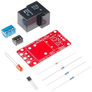
SparkFun Beefcake Relay Control Kit Ver. 2.0
SPARKFUN¥3,198税込¥3,5181個33日以内出荷Description。Your 5V system can wield great power with this big, beefy relay board. How does 10A on the NC contacts and 20A on the NO contacts at 220VAC sound? The SparkFun Beefcake Relay Control Kit contains all the parts you need to get your high-power load under control. Only minimal assembly is required!。The heart of the board is sealed, SPDT 20A/10A Relay. The relay is controlled by 5V logic through transistor, and an LED tells you when the relay is closed. This is kit, so it comes as through-hole parts with assembly required, which makes for some nice soldering practice. Screw terminal connectors on either side of the board make it easy to incorporate into your project.。There are some pretty beefy traces connecting the relay to the load pins, but the 3-pin terminals are only rated for 15A max! If you plan on connecting larger load, you'll need to solder directly to the board. As always with high current and voltage, play it safe and use your judgment when deciding how much of load you want to put on board -- in open airflow the PCB can handle the full 20A for few minutes at time, but in an enclosed area heat can build up.。Note:Please keep in mind that this board is really meant for someone with experience and good knowledge of electricity. If you're uncomfortable soldering or dealing with high voltage, please check out the IoT Power Relay. The IoT Power Relay is fully enclosed, making it lot safer.。Get Started With the Beefcake Hookup Assembly Guide。Features。Voltage Rating:220VAC/28VDC。VCC requirements:4-6V, 150mA capable。SPDT pins exposed(Form C)。14 AWG screw terminals for relay connections.。10 AWG solder lugs for relay connections.。Flyback diode included。Zener recovery diode included(decreases turn-off time)。Heavy oz. copper on PCBアズワン品番67-0424-03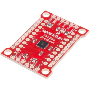
SparkFun 16 Output I/O Expander Breakout - SX1509
SPARKFUN¥2,198税込¥2,4181個33日以内出荷Description。Are you low on I/O? No problem! The SX1509 Breakout is 16-channel GPIO expander with an I2C interface that means with just two wires, your microcontroller can interface with 16 fully configurable digital input/output pins. But the SX1509 can do so much more than just simple digital pin control. It can produce PWM signals, so you can dim LEDs. It can be set to blink or even breathe pins at varying rates. This breakout is similar to multiplexer or "mux," in that it allows you to get more IO from less pins. And, with built-in keypad engine, it can interface with up to 64 buttons set up in an 8x8 matrix.。Two headers at the top and bottom of the breakout board function as the input and control headers to the board. This is where you can supply power to the SX1509, and where your I2C signals SDA and SCL will terminate. GPIO and power buses are broken out in every-which direction, and configurable jumpers cover most of the rest of the board.。Since the I/O banks can operate between 1.2V and 3.6V(5.5V tolerant)independent of both the core and each other, this device can also work as level-shifter. The SX1509 breakout makes it easy to prototype so you can add more I/O onto your Arduino or I/O limited controller. We've even spun up an Arduino Library to get you started!。Features。Enable Direct Level Shifting Between I/O Banks and Host Controller。5.5V Tolerant I/Os, Up to 15mA Output Sink on All I/Os。Integrated LED Driver with Intensity Control。On-Chip Keypad Scanning Engine Supports Up to 8x8 Matrix(64 Keys)。16 Channels of True Bi-directional Style I/O。400kHz I2C Compatible Slave Interfaceアズワン品番67-0419-88
LEDドライバ
SPARKFUN¥2,498税込¥2,7481個33日以内出荷Description。This is the FemtoBuck, a small-size single-output constant current LED driver. Each FemtoBuck has the capability to dim a single high-power channel of LEDs from 0-350mA at up to 36V while the dimming control can be either accessed via PWM or analog signal from 0-2.5V. This board is based off of the PicoBuck LED Driver, developed in collaboration with Ethan Zonca, except instead of blending three different LEDs on three different channels the FemtoBuck controls just one.。For the FemtoBuck, we've increased the voltage ratings on the parts to allow the input voltage to cover the full 36V range of the AL8805 driver. Since the FemtoBuck is a constant current driver, the current drawn from the supply will drop as supply voltage rises. In general, efficiency of the FemtoBuck is around 95%, depending on the input voltage. On board each FemtoBuck you will find two inputs for both power input and dimming control pins and an area to install a 3.5mm screw terminal. Finally at either side of the board you will find small indents or "ears" which will allow you to use a zip tie to secure the wires to the board after soldering them down. This version of the FemtoBuck is equipped with a small solder jumper that can be closed with a glob of solder to double the output current from 330mA to 660mA.アズワン品番67-0477-97