カテゴリ
- 学童・教育用品(22)
絞り込み
ブランド
- SPARKFUN
- ADATA(2)
- メディアカバーマーケット(44)
- セキスイ(20)
- SKC(環境測定)(14)
- ATEN(11)
- SKF(日本エスケイエフ)(10)
- DENALI(10)
- RS PRO(5)
- 積水成型工業(3)
- WatchGuard(3)
- BUFFALO(バッファロー)(2)
- 日本法令(2)
- MAD MAX(マッドマックス)(2)
- MOTO GRAFIX (モトグラフィックス)(2)
- Frameworks(フレームワークス)(2)
- A&D(エー・アンド・デイ)(1)
- 3M(スリーエム)(1)
- Merck(メルクミリポア)(1)
- ブランドをもっと見る
「adata」の検索結果
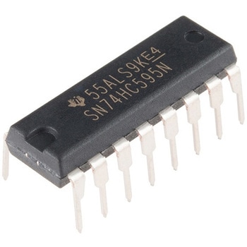
Shift Register 8-Bit - SN74HC595
SPARKFUN¥259税込¥2851個当日出荷Description。The SN74HC595N is a simple 8-bit shift register IC. Simply put, this shift register is a device that allows additional inputs or outputs to be added to a microcontroller by converting data between parallel and serial formats. Your chosen microprocessor is able to communicate with the The SN74HC595N using serial information then gathers or outputs information in a parallel(multi-pin)format. Essentially it takes 8 bits from the serial input and then outputs them to 8 pins.。This small DIP packaged IC contains an 8-bit, serial-in parallel-out shift register that feeds an 8-bit D-type storage register with parallel 3-state outputs.。Note:。This is a drop-in replacement for the 74HC595 shift register IC and should function just fine in any application the previous version could.。Get started with the Shift Register Guide。Features。8-Bit Serial-In, Parallel-Out Shift。Wide Operating Voltage Range of 2 V to 6 V。High-Current 3-State Outputs Can Drive Up to 15 LSTTL Loads。Low Power Consumption:80-μA。±6-mA Output Drive at 5 Vアズワン品番67-0420-82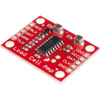
LOAD CELL AMP HX711
SPARKFUN¥3,500税込¥3,8501個33日以内出荷。Description。The SparkFun Load Cell Amplifier is a small breakout board for the HX711 IC that allows you to easily read load cells to measure weight. By connecting the amplifier to your microcontroller you will be able to read the changes in the resistance of the load cell, and with some calibration you'll be able to get very accurate weight measurements. This can be handy for creating your own industrial scale, process control or simple presence detection.。This version of the SparkFun Load Cell Amplifier features a few changes that you specifically asked for! We have separated the analog and digital supply, as well as added a 3.3uH inductor and a 0.1uF filter capacitor for digital supply. Need even more? Checkout the SparkFun Qwiic Scale. It has all the features of the HX711 but with additional library support, a true I2C interface, and no soldering required!。The HX711 uses a two-wire interface(Clock and Data)for communication. Any microcontroller's GPIO pins should work, and numerous libraries have been written, making it easy to read data from the HX711. Check the hookup guide below for more information.。Load cells use a four-wire Wheatstone bridge configuration to connect to the HX711. These are commonly colored RED, BLK, WHT, GRN and YLW. Each color corresponds to the conventional color coding of load cells:Red(Excitation+ or VCC)。Black(Excitation- or GND)。White(Amplifier-, Signal- or Output-)。Green(A+, S+ or O+)。Yellow(Shield)。The YLW pin acts as an optional input that is not hooked up to the strain gauge but is utilized to ground and shield against outside EMI(electromagnetic interference). Please keep in mind that some load cells might have slight variations in color coding.。Note:Special thanks to Bodge for supplying the Library for the HX711!。Get Started with the HX711 Load Cell Amplifier Guide。Features。Operation Voltage:2.7V--5V。Operation Current:< 1.5mA。Selectable 10SPS or 80SPS output data rate。Simultaneous 50 and 60Hz supply rejectionアズワン品番67-0362-17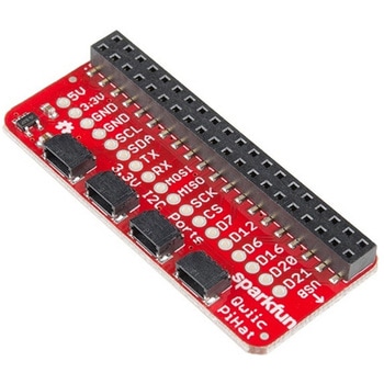
SparkFun Qwiic HAT for Raspberry Pi
SPARKFUN¥2,298税込¥2,5281個33日以内出荷Description。The SparkFun Qwiic HAT for Raspberry Pi is the quickest and easiest way to enter into SparkFun's Qwiic ecosystem while still using that Raspberry Pi that you've come to know and love. The Qwiic HAT connects the I2C bus(GND, 3.3V, SDA and SCL)on your Raspberry Pi to an array of Qwiic connectors on the HAT. Since the Qwiic system allows for daisy chaining boards with different addresses, you can stack as many sensors as you'd like to create a tower of sensing power!。The Qwiic Pi HAT has four Qwiic connect ports, all on the same I2C bus. In addition, many of the useful GPIO pins on the Raspberry Pi are broken out. This HAT is compatible with any Raspberry Pi that utilizes the standard 2x20 GPIO header. It has been designed to sit to the side of the Pi, allowing it to work conveniently with a Pi Tin enclosure to connect boards to the Qwiic ports.。Note:。There is a small silk error that has reversed the SDA and SCL. This is simply a cosmetic mix-up and will not impact any function with this board.。The SparkFun Qwiic Connect System is an ecosystem of I2C sensors, actuators, shields and cables that make prototyping faster and less prone to error. All Qwiic-enabled boards use a common 1mm pitch, 4-pin JST connector. This reduces the amount of required PCB space, and polarized connections mean you can't hook it up wrong.。Get Started with the SparkFun Qwiic Pi HAT Guide。Features。4x Qwiic Connection Ports。Select GPIO Pins Broken Out。Pi Tin Compatibilityアズワン品番67-0422-50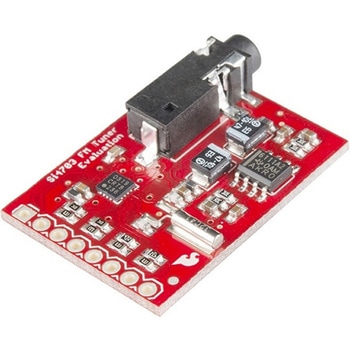
SparkFun FM Tuner Evaluation Board - Si4703
SPARKFUN¥7,298税込¥8,0281個33日以内出荷Description。This is an evaluation board for the Silicon Laboratories Si4703 FM tuner chip. Beyond enabling you to tune in to FM radio stations, the Si4703 is also capable of detecting and processing both Radio Data Service(RDS)and Radio Broadcast Data Service(RBDS)information. The Si4703 even does a very good job of filtering and carrier detection. It also enables data such as the station ID and song name to be displayed to the user.。Using this board, you will be able to pick up multiple stations just as well as with a standard FM radio. The board breaks out all major pins and makes it easy to incorporate this great chip into your next radio project. The power bus, the 3.3V and GND pins are broken out For communication. The breakout provides access to SDIO and SCLK for I2C communication while RST can be used for easy resetting. The SEN pin enables the user to change the mode of functionality of the IC. The last two pins broken out are GPIO1 and GPIO2 which can be used as general input/output pins, but also can be used for things like the RDS ready, seeking or tuning functions.。Keep in mind, by plugging headphones into the 3.5mm audio jack, you effectively use the cable in your headphones as an antenna! Therefore, this board does not require an external antenna if using headphones or a 3.5mm audio cable longer than 3 feet.アズワン品番67-0429-34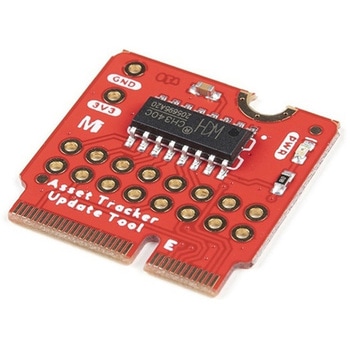
SparkFun MicroMod Update Tool
SPARKFUN¥1,798税込¥1,9781個33日以内出荷。Description。The SparkFun MicroMod Update Tool is built to interface with the MicroMod Asset Tracker Carrier Board and also makes it simple to communicate directly with the u-blox SARA-R510M8S module using u-blox's sophisticated m-center cellular evaluation software. If you're familiar with u-center, u-blox's GNSS evaluation software, you'll know how excellent their software is. m-center is every bit as good. Attach a USB-C cable and away you go!。The Update Tool is not a full MicroMod Processor Board, it is much simpler than that. It has a CH340C USB-Serial converter on it which gives you full access to all eight pins of the SARA-R5's UART interface via the Asset Tracker's USB-C connector. Think of it as a bridge from USB to serial.。The Update Tool features eight pairs of Plated Through Hole connections for the UART signals. You can use these to connect directly to the SARA UART using 3.3V signals if you want to. The split pads on the rear of the Tool can be opened to isolate the CH340C completely; the pins nearest the M.2 will link straight to the SARA UART.。Get Started with the MicroMod Update Tool Hookup Guide。Features。CH340C USB-Serial converter。Eight pairs of Plated Through Hole connections with split pad jumper links for:Serial Transmit(TX)。Serial Receive(RX)。Request To Send(RTS)。Clear To Send(CTS)。Data Terminal Ready(DTR)。Data Set Ready(DSR)。Ring Indicator(RI)。Data Carrier Detect(DCD)。LED indicator for:Power(3.3V)アズワン品番67-0423-52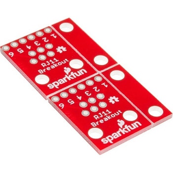
SparkFun RJ11 Breakout
SPARKFUN¥829税込¥9121個33日以内出荷。Description。This is the SparkFun RJ11 Breakout, two simple breakout boards for the common 6-pin RJ11 connector. These little boards can easily have one of our RJ11 6-Pin Connectors to work with common telephone cables. Each board features standard B/R/Y/G(Black/Red/Yellow/Green)labels on the top of the board to match a standard telephone wire. Additionally, each board has pin numbers on the back side that match with the pins on the connector.。Each breakout consists of two boards -- one for each end of the connections -- as well as mounting holes to help you secure your project in place.アズワン品番67-0420-01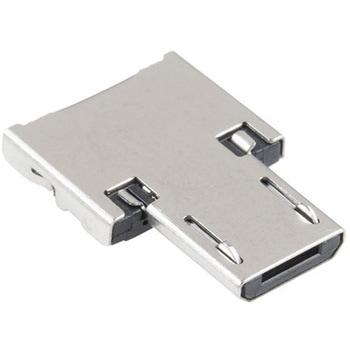
USB to Micro-B Adapter
SPARKFUN¥509税込¥5601個33日以内出荷Description。It's tiny, it's handy, and it can give your normal USB-equipped device a micro-B connector! With the USB to Micro-B Adapter you can make a flash drive connect to your tablet, connect a keyboard to your phone in order to text with ease, attach a Bluetooth(R)dongle to your RPi Zero, and more! Since this adapter is super small, it is very easy to transport anywhere you might need it --- making it extremely convenient to have in a pinch.。Installation of the USB to Micro-B Adapter is easy; simply slide it into a USB A connector, and you will instantly make that device micro-B capable!アズワン品番67-0421-07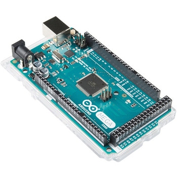
ArduinoMega 2560 R3
SPARKFUN¥18,980税込¥20,8781個33日以内出荷。Description。Arduino is an open-source physical computing platform based on a simple i/o board and a development environment that implements the Processing/Wiring language. Arduino can be used to develop stand-alone interactive objects or can be connected to software on your computer(e.g. Flash, Processing, MaxMSP). The open-source IDE can be downloaded for free(currently for Mac OS X, Windows, and Linux).。The Arduino Mega is a microcontroller board based on the ATmega2560. It has 54 digital input/output pins(of which 14 can be used as PWM outputs), 16 analog inputs, 4 UARTs(hardware serial ports), a 16 MHz crystal oscillator, a USB connection, a power jack, an ICSP header, and a reset button. It contains everything needed to support the microcontroller; simply connect it to a computer with a USB cable or power it with a AC-to-DC adapter or battery to get started.。Never fear for accidental electrical discharge, either since since the Mega also includes a plastic base plate to protect it!。The Mega 2560 R3 also adds SDA and SCL pins next to the AREF.。In addition, there are two new pins placed near the RESET pin. One is the IOREF that allow the shields to adapt to the voltage provided from the board.。The other is a not connected and is reserved for future purposes.。The Mega 2560 R3 works with all existing shields but can adapt to new shields which use these additional pins.。Not sure which Arduino or Arduino-compatible board is right for you? Check out our Arduino Buying Guide!。Features。ATmega2560 microcontroller。Input voltage - 7-12V。54 Digital I/O Pins(14 PWM outputs)。16 Analog Inputs。256k Flash Memory。16Mhz Clock Speedアズワン品番67-0349-13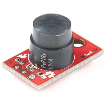
SparkFun PIR Breakout - 170uA EKMC4607112K
SPARKFUN¥5,498税込¥6,0481個33日以内出荷。Description。Passive Infrared(PIR)sensors are great for detecting motion in a small area around the sensor. The 170μA SparkFun EKMC4607112K PIR Breakout is a simple board equipped with an EKM-series PIR sensor from Panasonic(R). The EKM-series PIR sensors are optimized for small movements to offer motion-sensing options for continuously powered applications.。PIR sensors do not return specific distance data but instead monitor for IR light coming from objects in their field of view and will activate their signal when motion is detected in their sensing area, making them perfect for applications such as turning devices on automatically when motion is detected. Applications include home and building automation for energy saving, automated on/off lighting control, security, appliances, and IoT.。Panasonic's low-profile PIR motion sensors(10.9mm versus standard 14.4mm height offer space savings for constrained designs)consist of a lens to create various detection zones, an optical filter to block non-infrared light, pyroelectric sensing elements, electromagnetic shielding to all circuitry, and an impedance converter to get an electrical signal. This PIR sensor offers digital output across 32 zones at 5m detection distance with 90°×90° detection area.。Note:The sensitivity of passive infrared sensors is influenced by environmental conditions, so a performance evaluation test under representative conditions is recommended.。Get Started with the SparkFun PIR Breakout Guide。Features。Operating Voltage:2.3。-。4.0V。170 μA。standby current consumption。Lens diameter - 10.4mm。Lens Height - 10.9mm。5m detection distance。90°×90°(±45°)detection areaアズワン品番67-0427-43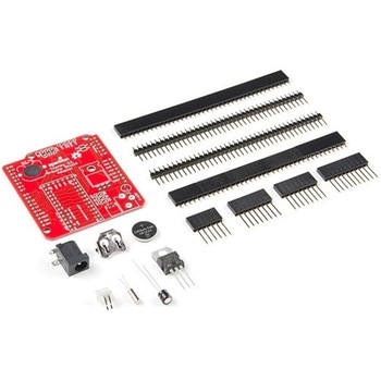
Teensy Arduino Shield Adapter
SPARKFUN¥4,798税込¥5,2781個33日以内出荷Description。The Teensy is an amazing and compact development platform in breadboard friendly form factor, but what if you could incorporate it into the Arduino architecture? The Teensy Arduino Shield Adapter allows you to attach your Teensy and utilize your favorite Arduino shields without the requirement of breadboard or any complicated wiring. Needless to say, the Teensy Arduino Shield Adapter is useful tool for upgrading all of your existing Arduino projects to more powerful controller!。As we stated before, the Teensy Arduino Shield Adapter provides basic Arduino compatibility with your run-of-the-mill shield but there are few other fun features that we've added on, as well. These features include Real Time Clock(RTC)battery, JST battery connector, 4-12V barrel jack connector, an ICSP header, and more. Because this board is simply an adapter, there is no special programming required to start working with the adapter. You will, however, need to program the Teensy for any Arduino shield you'd like to work with.。While the adapter design can fit the Teensy LC footprint, it has been designed to fully utilize the features of the Teensy 3.1. Not all of the features available on the adapter are compatible with the LC so please be sure to check the Hookup Guide in the。Documents。section below to ensure functionality for your project. Please keep in mind that this adapter may be incompatible with some 5V Arduino shields. Please check our hookup guide for more information.。Note:The Teensy Arduino Shield Adapter comes as kit and will need to be soldered together.。Note:Due to the requirements of shipping the batteries in this kit, orders may take longer to process and therefore do not qualify for same-day shipping. Additionally, these batteries can not be shipped via Ground or Economy methods to Alaska or Hawaii. Sorry for any inconvenience this may cause.。Features。Arduino R3 Interface。Real Time Clock Battery。JST Battery Connector。Barrel Jack。I2C Jumpers。ICSP Header。DAC Pin Headerアズワン品番67-0424-36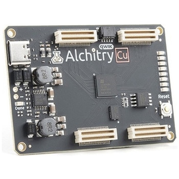
Alchitry Cu FPGA Development Board Lattice iCE40 HX
SPARKFUN¥15,980税込¥17,5781個33日以内出荷Description。If you are not needing a lot of power to start your FPGA adventure, or are looking for a more economical option, the Alchitry Cu FPGA Development Board might be the perfect option for you! The Alchitry Cu is a "lighter" FPGA version than the Alchitry Au but still offers something completely unique. FPGAs, or Field-Programmable Gate Arrays, are an advanced development board type for engineers and hobbyists alike to experience the next step in programming with electronics. The Cu truly exemplifies the trend of more affordable and increasingly powerful FPGA boards arriving each year. This board is a fantastic starting point into the world of FPGAs and the heart of your next project. Finally, now that this board is built by SparkFun, we added a Qwiic connector for easy I2C integration!。The Alchitry Cu uses the Lattice iCE40 HX FPGA with 7680 logic cells and is supported by the open source tool chain Project IceStorm. The Cu possesses 79 IO pins with eight general purpose LEDs; a 100MHz on-board clock that can be manipulated internally by the FPGA; a USB-C connector to configure and power the board; and a USB to serial interface for data transfer.。By adding stackable expansion boards similar to shields or HATs called "Elements," the Alchitry Cu is able to expand its own hardware capabilities by adding prototyping spaces, buttons, LEDs, and more!。The SparkFun Qwiic Connect System is an ecosystem of I2C sensors, actuators, shields and cables that make prototyping faster and less prone to error. All Qwiic-enabled boards use a common 1mm pitch, 4-pin JST connector. This reduces the amount of required PCB space, and polarized connections mean you can't hook it up wrong.。Get Started with our Learning FPGA Tutorials。Features。Lattice iCE40-HX8K FPGA - 7680 logic elements。79 IO pins(3.3V logic level)。USB-C to configure and power the board。Eight general purpose LEDs。One button(typically used as a reset)。100MHz on-board clock(can be multiplied internally by the FPGA)。Powered with 5V through USB-C port, 0.1" holes, or headers。USB to serial interface for data transfer(up to 12Mbaud)。Qwiic Connector。Dimensions of 65mm×45mm。。Examples。First FPGA Project - Getting Fancy with PWM。External IO and Metastabilityアズワン品番67-0423-08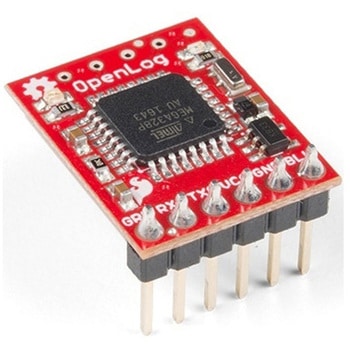
SparkFun OpenLog with Headers
SPARKFUN¥6,898税込¥7,5881個33日以内出荷Description。The SparkFun OpenLog with Headers is an open source data logger that works over a simple serial connection and supports microSD cards up to 64GB. The OpenLog can store or "log" huge amounts of serial data and act as a black box of sorts to store all the serial data that your project generates, for scientific or debugging purposes. This version of th OpenLog even includes pre-soldered headers for your convenience.。The SparkFun OpenLog uses an ATmega328 running at 16MHz thanks to the onboard resonator. The OpenLog draws approximately 2-3mA in idle(nothing to record)mode. During a full record OpenLog can draw 10 to 20mA depending on the microSD card being used.。All data logged by the OpenLog is stored on the microSD card. Any 512MB to 32GB microSD card should work. OpenLog supports both FAT16 and FAT32 SD formats.。For even better performance the OpenLog Artemis is the tool you need, featuring logging speeds up to 500000bps.。Get Started with the SparkFun OpenLog Guide。Features。VCC Input:3.3V-12V(Recommended 3.3V-5V)。Log to low-cost microSD FAT16/32 cards up to 32GB。Simple command interface。Configurable baud rates(up to 115200bps)。Preprogrammed ATmega328 and bootloader。Four SPI pogo pins。Two LEDs indicate writing status。2mA idle, 6mA at maximum recording rate。Pre-soldered Headersアズワン品番67-0422-30
SparkFun gator:log - micro:bit Accessory Board
SPARKFUN¥4,398税込¥4,8381個33日以内出荷Description。The gator:log is the perfect data logging tool for your next experiment. With the automation of the data collection process, gone are the days of rushing around with a pen and composition notebook to simultaneously record data and your observations. Now, you only need to sit back and observe your experiment.。The gator:log allows a student(s)to focus more on what is happening in the experiment than watching a thermometer or sensor readout. Additionally, a micro:bit can still be used to provide a graphical display for observing changes in data, when a sensor readout is required. If tied in conjunction with the gator:RTC, stop watches on time based experiments can become a thing of the past too(with the added benefit of more accurate timing results)!。The micro:bit is a pocket-sized computer that lets you get creative with digital technology. Between the micro:bit and our shield-like bit boards you can do almost anything while coding, customizing and controlling your micro:bit from almost anywhere! You can use your micro:bit for all sorts of unique creations, from robots to musical instruments and more. At half the size of a credit card, this versatile board has vast potential!。Get Started with the SparkFun gator:log Hookup Guide。Features。ATmega328P microcontroller。μSD(micro SD)card slot for μSD card for data storage。Two status indicator LEDs。Serial connection via RX and TX pads。GND and 3V3 pads for 3.3V power connectionアズワン品番67-0422-76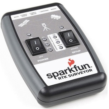
SparkFun RTK Surveyor
SPARKFUN¥129,800税込¥142,7801個33日以内出荷Description。The SparkFun RTK Surveyor is an easy to use GNSS receiver for centimeter-level positioning. Perfect for surveying, this preprogrammed device can also be used for autonomous driving, navigation, asset tracking and any other application where there is a clear view of the sky. The RTK Surveyor can also be used as a base station. With the flick of a switch, two RTK Surveyors can be used to create an RTK system capable of 14mm horizontal positional accuracy. The built-in Bluetooth(R)connection via an ESP32 WROOM enables the user to use the RTK Surveyor with their choice of GIS application on a phone or tablet. The built in battery allows field use for up to four hours and is compatible with common USB battery banks.。This device can be used in four modes:GNSS Positioning(~30cm accuracy)。GNSS Positioning with RTK(1.4cm accuracy)。GNSS Base Station。GNSS Base Station NTRIP Server。In Position mode the device receives L1/L2 signals from a user-provided antenna and the high-grade GNSS receiver provides lat/long and altitude with accuracies around 300mm.。In Positioning with RTK mode the device receives L1/L2 signals from the antenna and correction data from a base station. The correction data can be obtained from a cellular link to online correction sources or over a radio link to a 2nd RTK Surveyor setup as a base station.。In Base Station mode the device is mounted to a temporary position(like a tripod)and begins transmitting correction data over a radio or internet connection. A base is often used in conjunction with a second unit set to 'Positioning with RTK' to obtain the 14mm relative accuracy.。In Base Station NTRIP Server mode the device is mounted to a semi or permanently fixed position(like a roof)and connects over WiFi to transmit the correction data to a NTRIP caster so that any rover can access the correction data over a cellular or internet connection. This type of base is a very easy way to setup a very precise absolute correction source.。Two cables are provided with the RTK Surveyor allowing a user to plug on our easy to use Serial Telemetry Radios or their own radio link. If a local correction source is within 10km, a user can also use their phone to provide correction data over the Bluetooth(R)link(no external radio needed!).。Note:The SparkFun RTK Surveyor is just the enclosed device and does NOT include an antenna, serial telemetry radio, or associated mounting pieces. These items will need to be purchased separately from the Hookup Accessories below.。Get Started With the SparkFun RTK Surveyor Guide。Features。GNSS Receiver:ZED-F9P。Concurrent reception of GPS, GLONASS, Galileo and BeiDou。Receives both L1C/A and L2C bands。Current:68mA - 130mA(varies with constellations and tracking state)。Time to First Fix:25s(cold), 2s(hot)。Max Navigation Rate:PVT(basic location over UBX binary protocol)- 25Hz。RTK - 20Hz。Raw - 25Hz。Horizontal Position Accuracy:2.5m without RTK。0.010m with RTK。Max Altitude:50km(31 miles)。Max Velocity:500m/s(1118mph)。Bluetooth(R)Transceiver:ESP32 WROOM。Xtensa(R)dual-core 32-bit LX6 microprocessor。Up to 240MHz clock frequency。16MB of flash storage。520kB internal SRAM。Integrated 802.11 BGN WiFi transceiver。Integrated dual-mode Bluetooth(R)(classic and BLE)。Hardware accelerated encryption(AES, SHA2, ECC, RSA-4096)。2.5 μA deep sleep current。Overall Device。Internal Battery:LiPo 1000mAh with 500mA charging。Radio Port:3.3V TTL Serial(57600bps RTCM TX/RX)。Data Port:3.3V TTL Serial(115200bps NMEA)。Weight:132g(entire device including battery)。Dimensions:118mm×79mm×30mm(4.7in×3.1in×1.2in)。1x Qwiic Connector。1x microSD Socket for optional logging。Changes:This version(which replaces SPX-17369)uses a reinforced edge mount SMA connector for better resiliency when a fixed 'stub' antenna is used.アズワン品番67-0423-95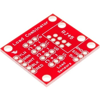
SparkFun Load Sensor Combinator
SPARKFUN¥839税込¥9231個33日以内出荷Description。The SparkFun Load Sensor Combinator is a bare PCB that combines four load sensors into a standard four-wire Wheatstone bridge configuration. If you open up an electronic bathroom scale, you'll find a large rat's nest of wires. The Load Sensor Combinator was created to combine the 12 wires found in a bathroom scale into the standard four-wire Wheatstone bridge configuration.。This version of the SparkFun Load Sensor Combinator features a few changes that you specifically asked for! We updated the silk on the breakout to read "C/+/-" instead of "R/W/B" and moved the temperature sensor connector away from the standoff hole.。You can either use four individual load sensors or simply purchase an off-the-shelf bathroom scale and hack the combinator into it rather than trying to design a base to properly mount four load sensors.。This board works great with our Load Cell Amplifier breakout board; the five pins on the edge of the combinator line up directly to the five pins on the amplifier.。If your amplifier and supporting electronics are more than a few inches away from the scale, an RJ45 footprint is provided. The four Wheatstone pins(E+/E-/S+/S-)as well as the shield pin are connected to twisted pairs within a standard cheap Ethernet cable. This allows the amplifier board to be placed many feet away from the scale itself.。The combinator board also includes a footprint for the DS18B20 one-wire temperature sensor. This allows the user to gather the temperature of the scale in case there is a large variance between the scale and the amplifier. These three pins are accessed through the RJ45 connection as well, allowing remote temperature readings to be gathered over one twisted pair Ethernet cable.。NOTE:。The SparkFun Load Sensor Combinator will only work with 3 wire load sensors, it is not compatible with 4 wire load cells.アズワン品番67-0419-93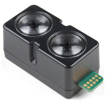
Garmin LIDAR-Lite v4 LED - Distance Measurement Sensor
SPARKFUN¥22,980税込¥25,2781個33日以内出荷Description。The LIDAR-Lite v4 LED sensor is the next step in the LIDAR-Lite line. A small, lightweight, low-power optical ranging sensor. It's the first to incorporate ANT profile wireless networking technology into an optical sensor. Its built-in nRF52840 processor means that developers can create custom applications, or be operated as a stand-alone device right out of the box by using the preloaded stock application.。Like the LIDAR-Lite v3 and LIDAR-Lite v3HP sensors; it can also be directly connected to an external micro-controller running a custom user application. As such, it provides a highly adaptable option for OEM and maker applications in robotics, Internet of Things, and unmanned vehicles ― or any application where an ultrasonic sensor might otherwise be used. It's perfect as the basic building block for applications where wireless capabilities, small size, light weight, low power consumption and high performance are important factors in a short-range, 10-meter, optical distance measuring sensor.。The LIDAR-Lite v4 requires an external 5VDC power source and soldering is required. This Time-of-Flight ranging module uses a LED and optics for ranging. It does not use a laser; therefore, it is inherently eye-safe under normal usage.。Features。Resolution:1 cm。Measurement repeatability:As measured indoors to a 90% reflective target。1 cm is equivalent to 1 standard deviation。Using "high accuracy" mode, with averaging:+/- 1 cm to 2 meters。+/- 2 cm to 4 meters。+/- 5 cm to 10 meters。Range:5 cm to 10 meters(as measured from back of unit)。Update rate:I2C = >200 Hz typical。ANT(R)= up to 200 Hz to a 90% target indoors at 2m in normal operating mode。Interface:I2C or ANT; user configurable for SPI using the Nordic SDK。Power(operating voltage):4.75 - 5.25 VDC。Current consumption:2mA idle, 85mA during acquisition。Operating temperature:-20 to 60° C。LED wavelength:940 nm。Beam divergence:4.77°。Optical aperture:14.9 mm。Unit size(HxWxD):2.1"×0.8"×0.9"(52.2×21.2×24.0 mm)。Weight:14.6 g(0.5 oz)アズワン品番67-0427-09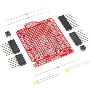
SparkFun ProtoShield Kit
SPARKFUN¥4,998税込¥5,4981個33日以内出荷Description。The SparkFun ProtoShield Kit lets you customize your own Arduino shield using whatever circuit you can come up with and then test it to make sure everything is working the way it should! The SparkFun ProtoShield Kit is based off the Arduino R3's footprint that allows you to easily incorporate it with favorite Arduino-based device.。One of our favorite features with this version of the ProtoShield Kit is the solderable-like breadboard prototyping area! Half of this area was designed with a breadboard in mind. On the underside of the shield you will be able to see open jumper pads between each through hole to make a connection like a breadboard. Once you add a component, simply add a solder jumper between holes to make a connection. For those that prefer the standard prototyping pads, we left the other side(near the BlueSMiRF and Serial UART ports)as is.。We have also moved the prototype testing components(those used to make sure your circuit works effectively)off of the "mainland" of the shield and onto a ProtoSnap styled, removable PCB. On this test area you will find soldering areas for the two yellow 3mm LEDs(as well as pins to control and power them), two 330 Ohm resistors, a 10K Ohm resistor, and a pushbutton.。Note:。Since this product is a kit, assembly and a basic knowledge of soldering will be required. The SparkFun ProtoShield Kit does not come pre-assembled.。Get Started With the SparkFun ProtoShield Kit Guide。Features。Arduino R3 Footprint。Soldering Kit。Solderable-Like Breadboard。BlueSMiRF or Comparable 6-pin Pins。Detachable Test Areaアズワン品番67-0422-25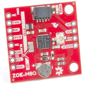
SparkFun GPS Breakout - ZOE-M8Q Qwiic
SPARKFUN¥14,980税込¥16,4781個33日以内出荷Description。The SparkFun ZOE-M8Q GPS Breakout is a high accuracy, miniaturized, GPS board that is perfect for applications that don't possess a lot of space. The on-board ZOE-M8Q is a 72-channel GNSS receiver, meaning it can receive signals from the GPS, GLONASS, BeiDou, and Galileo constellations. This increases precision and decreases lock time and thanks to the onboard rechargable battery you'll have backup power enabling the GPS to get a hot lock within seconds! Additionally, this u-blox receiver supports I2C(u-blox calls this Display Data Channel)which made it perfect for the Qwiic compatibility so we don't have to use up our precious UART ports. Utilizing our handy Qwiic system, no soldering is required to connect it to the rest of your system. However, we still have broken out 0.1"-spaced pins in case you prefer to use a breadboard.。U-blox based GPS products are configurable using the popular, but dense, windows program called u-center. Plenty of different functions can be configured on the ZOE-M8Q:baud rates, update rates, geofencing, spoofing detection, external interrupts, SBAS/D-GPS, etc. All of this can be done within the SparkFun Arduino Library. We've also made sure to configure the UART pin grouping on the breakout to an industry standard to insure that it easily connects to a Serial Basic.。The SparkFun ZOE-M8Q GPS Breakout is also equipped with an on-board rechargeable battery that provides power to the RTC on the ZOE-M8Q. This reduces the time-to-first fix from a cold start(~30s)to a hot start(~1s). The battery will maintain RTC and GNSS orbit data without being connected to power for up to five hours. Since the ZOE-M8Q is a tiny GPS receiver and to minimize its footprint, we've added a U.FL connector to allow the use of both large standard ceramic antennas as well as very small chip scale antennas.。Note:The I2C address of the ZOE-M8Q is 0x42 and is software configurable. A multiplexer/Mux is required to communicate to multiple ZOE-M8Q sensors on a single bus. If you need to use more than one ZOE-M8Q sensor consider using the Qwiic Mux Breakout.。The SparkFun Qwiic Connect System is an ecosystem of I2C sensors, actuators, shields and cables that make prototyping faster and less prone to error. All Qwiic-enabled boards use a common 1mm pitch, 4-pin JST connector. This reduces the amount of required PCB space, and polarized connections mean you can't hook it up wrong.。The ZOE-M8Q GPS Breakout can also be automatically detected, scanned, configured, and logged using the OpenLog Artemis datalogger system. No programming, soldering, or setup required!。Get Started With the SparkFun ZOE-M8Q Hookup Guide。Features。72-Channel GNSS Receiver。2.5m Horizontal Accuracy。18Hz Max Update Rate。Time-To-First-Fix:Cold:26s。Hot:1s。Max Altitude:50,000m。Max G:≦4。Max Velocity:500m/s。Velocity Accuracy:0.05m/s。Heading Accuracy:0.3 degrees。Time Pulse Accuracy:30ns。3.3V VCC and I/O。Current Consumption:~29mA Tracking GPS+GLONASS。Software Configurable。Geofencing。Odometer。Spoofing Detection。External Interrupt。Pin Control。Low Power Mode。Many others!。Supports NMEA, UBX, and RTCM protocols over UART or I2C interfacesアズワン品番67-0423-76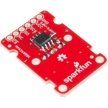
SparkFun Thermocouple Breakout - MAX31855K
SPARKFUN¥6,198税込¥6,8181個33日以内出荷Description。The SparkFun MAX31855K Thermocouple Breakout is a simple 14-bit resolution, SPI-compatible, serial interface thermocouple digitizer that makes reading a wide range of temperatures possible. A thermocouple works by taking two wires made of dissimilar metals, connecting them at the two ends, and making a temperature gradient between one end and the other(a 'hot' end and a 'cold' one). Once this is achieved, a voltage potential is formed and current flows. The SparkFun Thermocouple Breakout takes a standard Type-K thermocouple in one end, digitizes the temperature measured and sends that data out the other end via a SPI interface, thereby interpreting the data and translating it for you to read!。With the SparkFun Thermocouple Breakout, the thermocouple's hot junction can be read from -200℃ to +700℃ with an accuracy of ±2℃ while the cold junction, inside the MAX31855K, can only range from -20℃ to +85℃ while maintaining ±2℃ accuracy. The MAX31855K constantly measures the temperature of the cold junction using an internal temperature-sensing diode. The MAX31855K requires a power source from +3.0V to +3.6V(+3.0V nominal)and only draws 1.5mA maximum.。The Thermocouple Breakout is designed to accept a standard thermocouple connector, for convenience and compatibility with probes you may already own. These connectors aren't necessary, and you could solder a thermocouple directly into the through-holes labeled '+' and '-'. If you decide to solder the thermocouple directly to the breakout board, it is recommended that the thermocouple be mounted for strain relief to avoid breaking the thin wires. Notches for a zip-tie or wire wrapping have been provided in the PCB opposite the header for this purpose.。Features。14-bit Resolution。SPI-Compatible, Serial Interface。-200℃ to +700℃ Temperature Reading with ±2℃ Accuracy。3.0V to 3.6V(+3.0V nominal)Required。Accepts Type-K Thermocoupleアズワン品番67-0426-49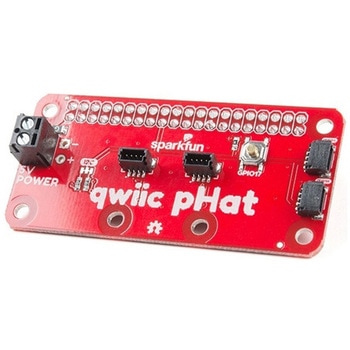
SparkFun Qwiic pHAT v2.0 for Raspberry Pi
SPARKFUN¥2,598税込¥2,8581個33日以内出荷。Description。The SparkFun Qwiic pHAT V2.0 for Raspberry Pi provides you with the quickest and easiest way to enter into SparkFun's Qwiic ecosystem while still using that Raspberry Pi that you've come to know and love. The Qwiic pHAT connects the I2C bus(GND, 3.3V, SDA, and SCL)on your Raspberry Pi to an array of Qwiic connectors on the HAT. Since the Qwiic system allows for daisy-chaining boards with different addresses, you can stack as many sensors as you'd like to create a tower of sensing power!。The Qwiic pHAT V2.0 has four Qwiic connect ports(two on its side and two vertical), all on the same I2C bus. We've also made sure to add a simple 5V screw terminal to power boards that may need more than 3.3V and a general-purpose button(with the option to shut down the Pi with a script). Also updated, the mounting holes found on the board are now spaced to accommodate the typical Qwiic board dimension of 1.0"×1.0". This HAT is compatible with any Raspberry Pi that utilizes the standard 2x20 GPIO header as well as the NVIDIA Jetson Nano and Google Coral.。Note。When placing a Raspberry Pi and the pHAT in an enclosure(like the Pi Tin), we noticed that the pHAT was not fully inserted in Pi's header pins. For a secure connection, you'll need to add a pair of 1x20 stackable headers to extend the pins to your cart.。The SparkFun Qwiic Connect System is an ecosystem of I2C sensors, actuators, shields and cables that make prototyping faster and less prone to error. All Qwiic-enabled boards use a common 1mm pitch, 4-pin JST connector. This reduces the amount of required PCB space, and polarized connections mean you can't hook it up wrong.。Get Started with the SparkFun Qwiic pHAT Guide。Features。4x Qwiic Connection Ports。1x 5V Tolerant Screw Terminal。1x General Purpose Button。HAT-compatible 40-pin Female Headerアズワン品番67-0422-97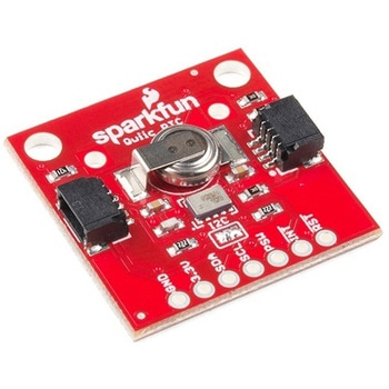
SparkFun Real Time Clock Module - RV-1805 Qwiic
SPARKFUN¥7,798税込¥8,5781個33日以内出荷Description。Get with the times, already! This SparkFun Real Time Clock(RTC)Module is a Qwiic-enabled breakout board for the RV-1805 chipset. The RTC is ultra-low power(running at only about 22nA in its lowest power setting)so it can use a supercapacitor for backup power instead of a normal battery. This means you get plenty of charge and discharge cycles without any degradation to the "battery." To make it even easier to get your readings, all communication is enacted exclusively via I2C, utilizing our handy Qwiic system so no soldering is required to connect it to the rest of your system. However, we still have broken out 0.1"-spaced pins in case you prefer to use a breadboard.。This RTC module's built in RV-1805 has not one, but two internal oscillators:a 32.768kHz tuning fork crystal and a low power RC based oscillator and can automatically switch between the two using the more precise crystal to correct the RC oscillator every few minutes. This feature allows the module to maintain a very accurate date and time with the worst case being +/- about three minutes over a year. The RV-1805 also has a built in trickle charger so as soon as the RTC is connected to power the it will be fully charged in under 10 minutes and has the ability to switch power to other systems allowing it to directly turn on or off a power hungry device such as a microcontroller or RF engine.。There is also the option to add a battery to the board if the supercapacitor just isn't going keep your project powered long enough(keep in mind, the supercap can hypothetically make the board keep time for around 35 days), you can solder on an external battery. That means you can let board sit with no power or connection to the outside world and the current hour/minute/second/date will be maintained.。Note:。The I2C address of the RV-1805 is 0x69 and is hardware defined. A multiplexer/Mux is required to communicate to multiple RV-1805 sensors on a single bus. If you need to use more than one RV-1805 sensor consider using the Qwiic Mux Breakout.。The SparkFun Qwiic connect system is an ecosystem of I2C sensors, actuators, shields and cables that make prototyping faster and less prone to error. All Qwiic-enabled boards use a common 1mm pitch, 4-pin JST connector. This reduces the amount of required PCB space, and polarized connections mean you can't hook it up wrong.。Get Started with the RV-1805 Real Time Clock Module Guide。Features。Operating Voltage(Startup):1.6V - 3.6V。Operating Voltage(Timekeeping):1.5V - 3.6V。Operating Temperature:-40℃ - 85℃。Time Accuracy:±2.0 ppm。Current Consumption:22nA(Typ.)。I2C Address:0xD2。Supercapacitor for Backup Power。2x Internal Oscillators。2x Qwiic Connectorsアズワン品番67-0420-02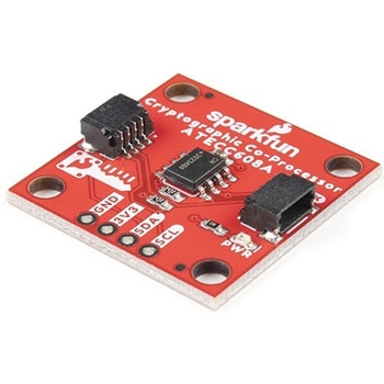
SparkFun Cryptographic Co-Processor Breakout - ATECC608A Qwiic
SPARKFUN¥1,498税込¥1,6481個33日以内出荷。Description。Product Restrictions:To access certain features of the ATECC608A, users will need to contact Microchip and sign an NDA contract to obtain the complete datasheet. Due to the required NDA - technical support, an Arduino library, and hookup guide are not provided for users on this product.。The SparkFun ATECC608A Cryptographic Co-processor Breakout allows you to add strong security to your IoT node, edge device, or embedded system. This includes。a。symmetric。authentication,。symmetric。AES-128 encryption/decryption, and much more. As stated above, the ATECC608A has limited Arduino support and the complete datasheet is under NDA with Microchip.。This breakout board includes two Qwiic ports for plug and play functionality. Utilizing our handy Qwiic system, no soldering is required to connect it to the rest of your system. However, we still have broken out 0.1"-spaced pins in case you prefer to use a breadboard. The ATECC608A chip is capable of many cryptographic processes, including, but not limited to:Creating and securely storing unique asymmetric key pairs based on Elliptic Curve Cryptography(FIPS186-3).。AES-128:Encrypt/Decrypt, Galois Field Multiply for GCM。Creating and verifying 64-byte digital signatures(from 32-bytes of message data).。Creating a shared secret key on a public channel via Elliptic Curve Diffie-Hellman Algorithm.。SHA-256 HMAC Hash including off-chip context save/restore。Internal high quality FIPS random number generator.。Embedded in the chip is a 10Kb EEPROM array that can be used for storing keys, certificates, data, consumption logging, and security configurations. Access to the sections of memory can then be restricted and the configuration locked to prevent changes. Each ATECC608A Breakout ships with a guaranteed unique 72-bit serial number and includes several security features to prevent physical attacks on the device itself, or logical attacks on the data transmitted between the device.。A summary datasheet for the ATECC608A is available here. The full datasheet is under NDA with Microchip. You will need to contact them for access to the entire datasheet. Meanwhile, the ArduinoATECCX08 Library currently only supports the ATECC608A with SAMD21 Arduino boards.。We do have much more support for the ATECC508A version of this chip. Please check out our ATECC508A Hookup Guide and Arduino Library(which includes six examples). This will get you familiar with the basics of elliptic curve cryptography and signing/verifying data with the ATECC508A version of the chip.。Note:The I2C address of the ATECC608A is 0x60 and is software-configurable to any address. A multiplexer/Mux is required to communicate to multiple ATECC608A sensors at the default address when on a single bus. If you need to use more than one ATECC608A sensor at the default address, consider using the Qwiic Mux Breakout.。Note:The ATECC608A can be only configured once before it is。PERMANENTLY。locked。. It is advisable that users purchase multiple boards in order to use other configurations and explore the advanced functions of the ATECC608A.。Additionally, this board。IS。capable of encrypting and decrypting data. However, to access these additional features, you will need to contact Microchip and sign an NDA contract to obtain the complete datasheet.。It is recommended that an SparkFun RedBoard Turbo - SAMD21 Development Board is used with this product due to the buffer size required on the I2C bus.。The SparkFun Qwiic Connect System is an ecosystem of I2C sensors, actuators, shields and cables that make prototyping faster and less prone to error. All Qwiic-enabled boards use a common 1mm pitch, 4-pin JST connector. This reduces the amount of required PCB space, and polarized connections mean you can't hook it up wrong.。。Features。Operating Voltage:2.0V-5.5V(。Default on Qwiic System:3.3V。)。Active Current Draw(for ATECC608A):16 mA。Sleep Current(for ATECC608A):<150 nA。Guaranteed Unique 72-bit Serial Number。10 Kb EEPROM Memory for Keys, Certificates, and Data。Storage for up to 16 Keys。256-bit Key Length。Internal High-Quality FIPS Random Number Generator(RNG)。Configurable I2C Address(7-bit):0x60(。Default。)アズワン品番67-0423-59