カテゴリ
- 学童・教育用品(27)
- 制御機器(2)
絞り込み
ブランド
- SPARKFUN
- モノタロウ(1)
- B+COM(11)
- SYGN HOUSE(サインハウス)(14)
- フエニックス・コンタクト(292)
- StarTech.com(54)
- RS PRO(43)
- TE Connectivity Japan(旧:TYCOELECTRONICS(タイコエレクトロニクス))(33)
- ラムマウント(21)
- メディアカバーマーケット(20)
- ホンダ(12)
- MICROCHIP(12)
- omron(オムロン)(10)
- wacom(ワコム)(9)
- AMPHENOL(7)
- ABL Components(5)
- シュナイダーエレクトリック(4)
- エレコム(3)
- タカチ電機工業(3)
- SONY(ソニー)(2)
- ブランドをもっと見る
「b com one」の検索結果
特価
 の全商品がキャンペーンコード入力で通常価格より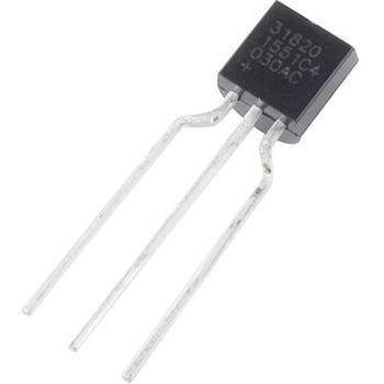
One-Wire Ambient Temperature Sensor - MAX31820
SPARKFUN¥1,598税込¥1,7581個33日以内出荷。Description。The MAX31820 ambient temperature sensor provides 9-bit to 12-bit Celsius temperature measurements with ±0.5℃ accuracy over a +10℃ to +45℃ temperature range. Over its entire -55℃ to +125℃ operating range, the device has ±2.0℃ accuracy.。The device communicates over a one-wire bus that, by definition, requires only one data line(and ground)for communication with a central microprocessor. In addition, the device can derive power directly from the data line, eliminating the need for an external power supply. Requiring so few pins enables the device to be placed in a 3-pin TO-92 package. The form factor of this package allows the device to be placed above the board and thus measure the ambient temperature of a system, as opposed to the board temperature that a surface-mount package would measure.。Each MAX31820 has a unique 64-bit serial code, which allows multiple MAX31820 devices to function on the same one-wire bus. Therefore, it is simple to use one microprocessor to control many devices distributed over a large area.。Features。Unique one-wire interface requires only one port pin for communication。Each device has a unique 64-bit serial code stored in onboard ROM。Multidrop capability simplifies distributed temperature-sensing applications。Requires no external components。Can be powered from data line; 3.0V to 3.7V power-supply range。Measures temperatures from -55℃ to +125℃。±0.5℃ accuracy from +10℃ to +45℃。Thermometer resolution is user-selectable from 9 bits to 12 bits。Converts temperature to 12-bit digital word in 750ms(Max)。User-definable nonvolatile(NV)alarm settings。Alarm search command identifies and addresses devices whose temperature is outside programmed limits(Temperature Alarm Condition)。Available in 3-pin TO-92 package。TO-92 package allows measurement of ambient temperature。Software compatible with the DS1822 and DS18B20アズワン品番67-0426-62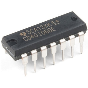
Schmitt Trigger - CD40106B
SPARKFUN¥759税込¥8351個23日以内出荷Description。The CD40106BE consists of six Schmitt-trigger circuits. Each circuit functions as an inverter with Schmitt-trigger action on the input. The trigger switches at different points for positive- and negative-going signals. The difference between the positive-going voltage(VP)and the negative-going voltage(VN)is defined as hysteresis voltage(VH).。Features。Schmitt trigger action with no external components。Hysteresis voltage typ. at 0.9V at VDD = 5V, 2.3V at VDD = 10V, and 3.5V at VDD = 15V。Noise immunity greater than 50%。No limit on input rise and fall times。Standardised, symmetrical output characteristics。100% tested for quiescent current at 20sV。Maximum input current of 1μA at 18 V over full package temperature range; 100nA at 18V and 25℃。Low VDD to VSS current during slow input rampアズワン品番67-0420-89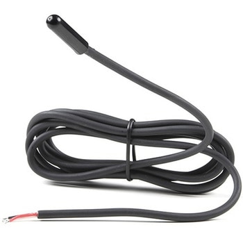
Temperature Sensor - High Temperature, Waterproof DS18B20
SPARKFUN¥3,698税込¥4,0681個欠品中Description。This sealed digital temperature probe lets you precisely measure temperatures in wet environments with a simple 1-Wire interface. The DS18B20 provides 9 to 12-bit(configurable)temperature readings over a 1-Wire interface, so that only one wire(and ground)needs to be connected from a central microprocessor. Power for reading, writing, and performing temperature conversions can be derived from the data line itself with no need for an external power source.。Because each DS18B20 contains a unique silicon serial number, multiple DS18B20s can exist on the same 1-Wire bus. This allows for placing temperature sensors in many different places. Applications where this feature is useful include HVAC environmental controls, sensing temperatures inside buildings, equipment or machinery, and process monitoring and control.。Note:The pinout for this sensor is as follows:RED=Vcc BLACK=GND WHITE=SIG。Features。3.0-5.5V input voltage。-55℃ to +125℃ temperature range。±0.5℃ accuracy from -10℃ to +85℃。Waterproof。1 Wire interface。Probe is 7mm in diameter and roughly 26mm long. Overall length(including wire)is 6 feet.。Thermometer resolution is programmable from 9 to 12 bits.。Electrical performance:no flicker or breakdown within AC 1200V/1S ,within DC 500V theinsulation resistance shall be greater than 100MΩアズワン品番67-0427-57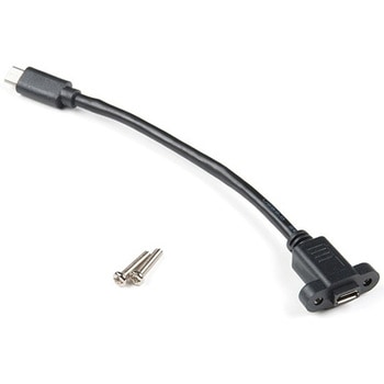
Panel Mount USB Micro-B Extension Cable - 6"
SPARKFUN¥1,398税込¥1,5381個25日以内出荷Description。This panel mount USB micro-B extension cable enables you to more easily enclose a project that contains a USB micro-B port. The cable is 6" in length and includes two 14mm M3 screws compatible with the cable's 3mm panel mount holes, spaced 16.5mm apart.アズワン品番67-0420-58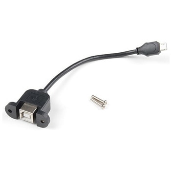
Panel Mount USB-B to Micro-B Cable - 6"
SPARKFUN¥1,198税込¥1,3181個33日以内出荷Description。This panel mount USB-B(female)to micro-B(male)cable enables you to more easily enclose a project that contains a USB micro-B port. The cable is 6" in length and includes two 14mm M3 screws compatible with the cable's 3mm panel mount holes, spaced 28.5mm apart.アズワン品番67-0420-57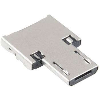
USB to Micro-B Adapter
SPARKFUN¥509税込¥5601個33日以内出荷Description。It's tiny, it's handy, and it can give your normal USB-equipped device a micro-B connector! With the USB to Micro-B Adapter you can make a flash drive connect to your tablet, connect a keyboard to your phone in order to text with ease, attach a Bluetooth(R)dongle to your RPi Zero, and more! Since this adapter is super small, it is very easy to transport anywhere you might need it --- making it extremely convenient to have in a pinch.。Installation of the USB to Micro-B Adapter is easy; simply slide it into a USB A connector, and you will instantly make that device micro-B capable!アズワン品番67-0421-07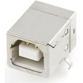
USB Female Type B Connector
SPARKFUN¥479税込¥5271個33日以内出荷USB Type 'B' Female connector. The 4 connection pins have .1" spacing allowing it to be inserted into development boards and perf boards with mild modification. You can either drill two 80mil holes for the support posts、or cut them off completely.アズワン品番67-0454-07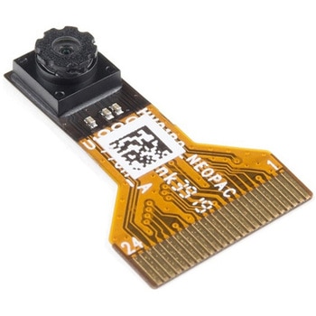
Himax CMOS Imaging Camera - HM01B0
SPARKFUN¥3,698税込¥4,0681個33日以内出荷。Description。The HM01B0 from Himax Imaging is an ultra low power CMOS Monochrome Image Sensor that enables the integration of an "Always On" camera for computer vision applications such as gestures, intelligent ambient light and proximity sensing, tracking and object identification. The sensor allows the sensor to consume very low power of <2mW at QVGA 30FPS. This low power consumption and vision applications camera comes with a ribbon cable that mates to the camera connector populated on the following products:MicroMod Machine Learning Carrier Board。Artemis Development Kit。Edge Development Board - Apollo3 Blue。The HM01B0 contains 320×320 pixel resolution and supports a 320×240 window mode which can be readout at a maximum frame rate of 60FPS, and a 2×2 monochrome binning mode with a maximum frame rate of 120FPS. The video data is transferred over a configurable 1bit, 4bit or 8bit interface with support for frame and line synchronization. The sensor integrates black level calibration circuit, automatic exposure and gain control loop, self-oscillator and motion detection circuit with interrupt output to reduce host computation and commands to the sensor to optimize the system power consumption.。Features。Image Sensor。Ultra Low Power Image Sensor(ULPIS)designed for Always On vision devices and applications。High sensitivity 3.6μ BrightSenseTM pixel technology。320×320 active pixel resolution with support for QVGA window, vertical flip and horizontal mirror readout。Programmable black level calibration target, frame size, frame rate, exposure, analog gain(up to 8x)and digital gain(up to 4x)。Automatic exposure and gain control loop with support for 50 / 60Hz flicker avoidance。Flexible 1bit, 4bit and 8bit video data interface with video frame and line sync。Motion Detection circuit with programmable ROI and detection threshold with digital output to serve as an interrupt。On-chip self oscillator。I2C 2-wire serial interface for register access。High CRA for low profile module design。Sensor Parameters。Active Pixel Array 320×320。Pixel Size 3.6 μm×3.6 μm。Full Image Area 1152 μm×1152 μm。Diagonal(Optical Format)1.63 mm(1/11″)。Scan Mode:Progressive。Shutter Type:Electronic Rolling Shutter。Frame Rate MAX 51 fps @ 320×320, 60 fps @ 320×240(QVGA)。CRA(maximum)30℃。Sensor Specifications。Supply Voltage:Analog - 2.8 V, Digital - 1.5V(Internal LDO:1.5V - 2.8V), I/O - 1.5 - 2.8V。Input Reference Clock:3 - 50 MHz。Serial Interface(I2C):2-wire, 400 KHz max.。Video Data Interface:1b, 4b, 8b with frame / line SYNC。Output Clock Rate MAX:50 MHz for 1bit, 12.5 MHz for 4bit, 6.25 MHz for 8bit。Est. Power Consumption(include IO with 5pF load):QVGA 60FPS(Typical)<4 mW。QVGA 30FPS(Typical)<2 mWアズワン品番67-0427-08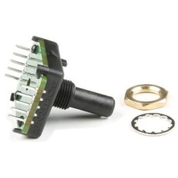
Bourns Absolute Encoder EAW0J-B24-AE0128L
SPARKFUN¥3,500税込¥3,8501個33日以内出荷。Description。The Bourns Absolute Encoder is a digital control knob that provides 128 unique results evenly spaced around a full circle. It is designed as a control panel knob but can be adapted for other uses. This can be a good alternative to using a potentiometer and analog pin, as this allows for full-turn and multi-turn operation.。It differs from the more common incremental rotary encoder which has only two or four values in a rotation and is designed to measure full rotations and direction. This measures。angles。and absolute position is maintained between power cycles.。Features。128 rotary positions。360 degree continuous rotation。Rotational life - 50,000 revolutions(min)。Max RPM - up to 120。Absolute digital output will retain its last position between power cycles or in the event of a power failure。Threaded M9x0.75 in. bushing。3/4 in. rotating encoder shaft。Rear mount terminalsアズワン品番67-0421-27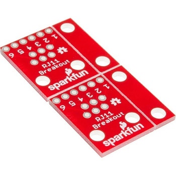
SparkFun RJ11 Breakout
SPARKFUN¥829税込¥9121個33日以内出荷。Description。This is the SparkFun RJ11 Breakout, two simple breakout boards for the common 6-pin RJ11 connector. These little boards can easily have one of our RJ11 6-Pin Connectors to work with common telephone cables. Each board features standard B/R/Y/G(Black/Red/Yellow/Green)labels on the top of the board to match a standard telephone wire. Additionally, each board has pin numbers on the back side that match with the pins on the connector.。Each breakout consists of two boards -- one for each end of the connections -- as well as mounting holes to help you secure your project in place.アズワン品番67-0420-01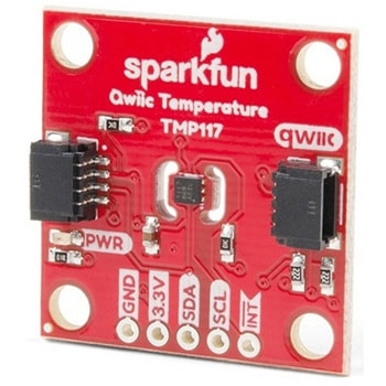
SparkFun High Precision Temperature Sensor - TMP117 Qwiic
SPARKFUN¥4,898税込¥5,3881個26日以内出荷。Description。The SparkFun Qwiic TMP117 breakout is a high precision temperature sensor equipped with an I2C interface. It outputs temperature readings with high precision of ±0.1℃ across the temperature range of -20℃ to +50℃s with no calibration and a maximum range from -55℃ to 150℃. The SparkFun High Precision Temperature Sensor also has a very low power consumption rate which minimizes the impact of self-heating on measurement accuracy. Utilizing our handy Qwiic system, no soldering is required to connect it to the rest of your system. However, we still have broken out 0.1"-spaced pins in case you prefer to use a breadboard.。The SparkFun High Precision Temperature Sensor also includes programmable temperature limits, and digital offset for system correction. While the TMP102 is capable of reading temperatures to a resolution of 0.0625℃ and is accurate up to 0.5℃, the on-board TMP117 is not only more precise but has a 16-bit resolution of 0.0078℃!。To make this breakout even easier to use, we've written an Arduino library to help you get started "Qwiic-ly." Check the Documents tab above for more information.。The SparkFun Qwiic Connect System is an ecosystem of I2C sensors, actuators, shields and cables that make prototyping faster and less prone to error. All Qwiic-enabled boards use a common 1mm pitch, 4-pin JST connector. This reduces the amount of required PCB space, and polarized connections mean you can't hook it up wrong.。The TMP117 High Precision Temperature Sensor can also be automatically detected, scanned, configured, and logged using the OpenLog Artemis datalogger system. No programming, soldering, or setup required!。Need a custom board? This component can be found in SparkFun's A La Carte board builder. You can have a custom design fabricated with this component - and your choice of hundreds of other sensors, actuators and wireless devices - delivered to you in just a few weeks.。Get Started with the SparkFun High Precision TMP117 Hookup Guide。Features。Uses I2C interface(Qwiic-enabled)。Four selectable addresses。0x48(default), 0x49, 0x4A, 0x4B。16-bit resolution, 0.0078℃。High accuracy, digital temperature sensor。±0.1℃(max)from ?20℃ to 50℃。±0.15℃(max)from ?40℃ to 70℃。±0.2℃(max)from ?40℃ to 100℃。±0.25℃(max)from ?55℃ to 125℃。±0.3℃(max)from ?55℃ to 150℃。Operating temperature range。-55℃ to +150℃。Operating voltage range。1.8V to 5.5V。Typically 3.3V if using the Qwiic cable。Low power consumption。3.5μA(1-Hz conversion cycle)。150nA(shutdown current)。Programmable operating modes。Continuous, one-shot, and shutdown。Programmable temperature alert limits。Selectable averaging for reduced noise。Digital offset for system correction。NIST traceability。。Documents。Schematic。Eagle Files。Board Dimensions。Hookup Guide。Datasheet(TMP117)。Arduino Library。GitHub Hardware Repoアズワン品番67-0427-10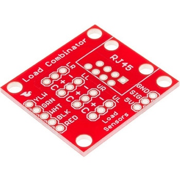
SparkFun Load Sensor Combinator
SPARKFUN¥839税込¥9231個33日以内出荷Description。The SparkFun Load Sensor Combinator is a bare PCB that combines four load sensors into a standard four-wire Wheatstone bridge configuration. If you open up an electronic bathroom scale, you'll find a large rat's nest of wires. The Load Sensor Combinator was created to combine the 12 wires found in a bathroom scale into the standard four-wire Wheatstone bridge configuration.。This version of the SparkFun Load Sensor Combinator features a few changes that you specifically asked for! We updated the silk on the breakout to read "C/+/-" instead of "R/W/B" and moved the temperature sensor connector away from the standoff hole.。You can either use four individual load sensors or simply purchase an off-the-shelf bathroom scale and hack the combinator into it rather than trying to design a base to properly mount four load sensors.。This board works great with our Load Cell Amplifier breakout board; the five pins on the edge of the combinator line up directly to the five pins on the amplifier.。If your amplifier and supporting electronics are more than a few inches away from the scale, an RJ45 footprint is provided. The four Wheatstone pins(E+/E-/S+/S-)as well as the shield pin are connected to twisted pairs within a standard cheap Ethernet cable. This allows the amplifier board to be placed many feet away from the scale itself.。The combinator board also includes a footprint for the DS18B20 one-wire temperature sensor. This allows the user to gather the temperature of the scale in case there is a large variance between the scale and the amplifier. These three pins are accessed through the RJ45 connection as well, allowing remote temperature readings to be gathered over one twisted pair Ethernet cable.。NOTE:。The SparkFun Load Sensor Combinator will only work with 3 wire load sensors, it is not compatible with 4 wire load cells.アズワン品番67-0419-93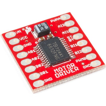
モータードライバ
SPARKFUN¥4,798税込¥5,2781個33日以内出荷Description。The TB6612FNG Motor Driver can control up to two DC motors at a constant current of 1.2A(3.2A peak). Two input signals(IN1 and IN2)can be used to control the motor in one of four function modes:CW, CCW, short-brake and stop. The two motor outputs(A and B)can be separately controlled, and the speed of each motor is controlled via a PWM input signal with a frequency up to 100kHz. The STBY pin should be pulled high to take the motor out of standby mode.。Logic supply voltage(VCC)can be in the range of 2.7--5.5VDC, while the motor supply(VM)is limited to a maximum voltage of 15VDC. The output current is rated up to 1.2A per channel(or up to 3.2A for a short, single pulse).。This little board comes with all components installed as shown. Decoupling capacitors are included on both supply lines. All pins of the TB6612FNG are broken out to two 0.1" pitch headers; the pins are arranged such that input pins are on one side and output pins are on the other.。Note:。If you are looking for the SparkFun Motor Driver with headers, it can be found here or in the。Similar Products。below.。Get Started With the Motor Driver Hookup Guide。Features。Power supply voltage:VM = 15V max, VCC = 2.7--5.5V。Output current:Iout = 1.2A(average)/ 3.2A(peak)。Standby control to save power。CW/CCW/short-brake/stop motor control modes。Built-in thermal shutdown circuit and low-voltage detecting circuit。All pins of the TB6612FNG broken out to 0.1" spaced pins。Filtering capacitors on both supply linesアズワン品番67-0395-99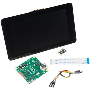
Raspberry Pi 7インチLCDタッチスクリーン
SPARKFUN¥35,980税込¥39,5781セット33日以内出荷Description。This 7" Raspberry Pi Touchscreen LCD provides you with the ability to create a standalone device that can be utilized as a custom tablet or an all-in-one interactive interface for a future project using your Raspberry Pi 3. Each LCD features a full color 800×480 capacitive touch display that connects to the Pi via an included adapter board which handles all of your power and signal conversion needs. An updated version of Raspbian OS on the A+, B+ and Pi2B is required for the display to work(the display does not work with the current version of Raspbian available on the Model A or B).。What makes this LCD great is the fact that it only requires two connections to be hooked up to the Pi; power from the Pi's GPIO port and a ribbon cable that connects to the DSI port present on all Raspberry Pi's. Touchscreen drivers with support for 10-finger touch and an on-screen keyboard allow you to use your Raspberry Pi without an external keyboard or mouse.。With this Raspberry Pi LCD you can create your own 'Internet of Things'(IoT)devices including a visual display by simply connecting your Pi, developing a easy Python script to interact with the display, and you'll be ready to create your own home automation devices with touch screen capability.。Note:The latest version of Raspbian OS is required for this Raspberry Pi LCD to operate correctly.。Features。7" Touchscreen Display.。Screen Dimensions:194mm×110mm×20mm(including standoffs)。Viewable screen size:155mm×86mm。70 degree viewing angle。Screen Resolution 800×480 pixels @ 60fps。24-bit color。10 finger capacitive touch.。Connects to the Raspberry Pi board using a ribbon cable connected to the DSI port.。Adapter board is used to power the display and convert the parallel signals from the display to the serial(DSI)port on the Raspberry Pi.アズワン品番67-0457-43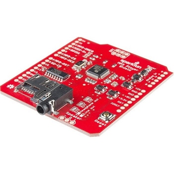
SparkFun MP3 Player Shield
SPARKFUN¥11,980税込¥13,1781個33日以内出荷Description。The SparkFun MP3 Player Shield is an awesome MP3 decoder with the capabilities of storing music files onto a run-of-the-mill microSD card, thus giving you the ability toadd music or sound effects to any project. With this board you can pull MP3 files from an microSD card and play them using only one shield, effectively turning any Arduino into a fully functional stand-alone MP3 player! The MP3 Shield utilizes the VS1053B MP3 audio decoder IC to decode audio files. The VS1053 is also capable of decoding Ogg Vorbis/MP3/AAC/WMA/MIDI audio and encoding IMA ADPCM and user-loadable Ogg Vorbis.。The VS1053 receives its input bitstream through a serial input bus(SPI). After the stream has been decoded by the IC, the audio is sent out to both a 3.5mm stereo headphone jack, as well as a 2-pin 0.1" pitch header.。This shield comes populated with all components as shown in the images and schematic; but it does not come with headers installed. We recommend the Arduino R3 Stackable Header Kit.。Features。3.5mm audio out jack。0.1" spaced header for speaker out。microSD card slotアズワン品番67-0422-08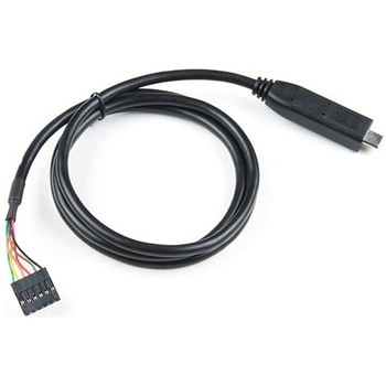
FTDI to USB-C Cable - 5V VCC-3.3V I/O
SPARKFUN¥7,998税込¥8,7981個33日以内出荷。Description。USB C is quickly becoming more and more prominent in the maker community because, let's be honest, who likes trying three times to insert USB into a port? This FTDI cable is a USB C to Serial converter which allows for a simple way to connect TTL interface devices to USB. Each 26AWG cable is one meter in length with the USB C side protected by a 2in enclosure.。The FTDI cable is designed around an RS232, which is housed in a USB C connector. The other side of the cable is terminated with a 0.1" pitch, 6-pin connector with the following pinout:RTS(Green), RX(Yellow), TX(Orange), VCC 5V(Red), CTS(Brown), GND(Black). This FTDI to USB C Cable is also capable of handling high voltages up to 300V max.。There are pros and cons to the FTDI Cable vs the FTDI Basic. The FTDI Basic has great LED indicators, but requires a Mini-B cable. The FTDI Cable is well protected against the elements, but is large and cannot be embedded into a project as easily. The FTDI Basic uses DTR to cause a hardware reset where the FTDI cable uses the RTS signal.アズワン品番67-0420-42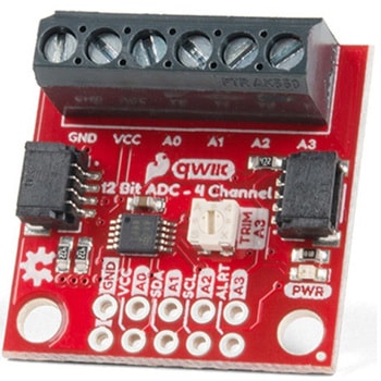
QWIIC 12BIT 4CHANNEL ADS1015
SPARKFUN¥5,498税込¥6,0481個33日以内出荷Description。A lot of the time you just need to add more analog inputs to solve a problem. It happens. The SparkFun Qwiic 12 Bit ADC can provide four channels of I2C controlled ADC input to your Qwiic enabled project. These channels can be used as single-ended inputs, or in pairs for differential inputs. What makes this even more powerful is that it has a programmable gain amplifier that lets you "zoom in" on a very small change in analog voltage(but will still effect your input range and resolution). Utilizing our handy Qwiic system, no soldering is required to connect it to the rest of your system. However, we still have broken out 0.1"-spaced pins in case you prefer to use a breadboard.。The ADS1015 uses its own internal voltage reference for measurements, but a ground and 3.3V reference are also available on the pin outs for users. This ADC board includes screw pin terminals on the four channels of input, allowing for solderless connection to voltage sources in your setup. It also has an address jumper that lets you choose one of four unique addresses(0x48, 0x49, 0x4A, 0x4B). With this, you can connect up to four of these on the same I2C bus and have sixteen channels of ADC. The maximum resolution of the converter is 12-bits in differential mode and 11-bits for single-ended inputs. Step sizes range from 125μV per count to 3mV per count depending on the full-scale range(FSR)setting.。We have included an onboard 10K trimpot connected to channel A3. This is handy for initial setup testing and can be used as a simple variable input to your project. But don't worry, we added an isolation jumper so you can use channel A3 however you'd like.。Note:The I2C address of the ADS1015 is 0x48 and is jumper selectable to 0x49, 0x4A, 0x4B. A multiplexer/Mux is required to communicate to multiple ADS1015 sensors on a single bus. If you need to use more than one ADS1015 sensor consider using the Qwiic Mux Breakout.。The SparkFun Qwiic connect system is an ecosystem of I2C sensors, actuators, shields and cables that make prototyping faster and less prone to error. All Qwiic-enabled boards use a common 1mm pitch, 4-pin JST connector. This reduces the amount of required PCB space, and polarized connections mean you can't hook it up wrong.。Get Started with the SparkFun Qwiic 12-Bit ADC Hookup Guide。Features。ADS1015。Operating Voltage(VDD):2.0V-5.5V。(Note:When powering with a Qwiic cable, the input range is only 3.3v)。Operating Temperature:-40℃ to 125℃。Operation Modes:Single-Shot, Continuous-Conversion(Default), and Duty Cycling。Analog Inputs:Measurement Type:Single-Ended(Default)。Input Voltage Range:GND to VDD。Full Scale Range(FSR):±.256V to ±6.114V(Default:2.048V)。Resolution:12-bit(Differential)or 11-bit(Single-Ended)。LSB size:0.125mV - 3mV(Default:1 mV)。Sample Rate:128 Hz to 3.3 kHz(Default:1600SPS)。Current Consumption(Typical):150μA-200μA。I2C Address:0x48(Default), 0x49, 0x4A, or 0x4B。Screw pin terminals for solderless connection to voltage sources。Four unique I2C addresses:0x48。0x49。0x4A。0x4B。2x Qwiic connection ports。Onboard 10K trimpotアズワン品番67-0360-13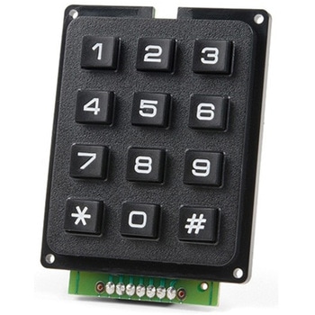
SparkFun Qwiic Keypad - 12 Button
SPARKFUN¥4,198税込¥4,6181個33日以内出荷Description。Keypads are very handy input devices, but who wants to tie up seven GPIO pins, wire up handful of pull-up resistors, and write firmware that wastes valuable processing time scanning the keys for inputs? The SparkFun Qwiic Keypad comes fully assembled and makes the development process for adding 12 button keypad easy. No voltage translation or figuring out which I2C pin is SDA or SCL, just plug and go! Utilizing our handy Qwiic system, no soldering is required to connect it to the rest of your system. However, we still have broken out 0.1"-spaced pins in case you prefer to use breadboard.。Each of the keypad's 12 buttons has been labeled 1, 2, 3, 4, 5, 6, 7, 8, 9, 0, *, and and has been formatted to into the same layout as telephone keypad with each keypress resistance ranging between 10 and 150 Ohms. The Qwiic Keypad reads and stores the last 15 button presses in First-In, First-Out(FIFO)stack, so you don't need to constantly poll the keypad from your microcontroller. This information, then, is accessible through the Qwiic interface. The SparkFun Qwiic Keypad even has software configurable I2C address so you can have multiple I2C devices on the same bus.。NOTE:The I2C address of the Qwiic Keypad is 0x4B and is jumper selectable to 0x4A(software-configurable to any address). multiplexer/Mux is required to communicate to multiple Qwiic Keypad sensors on single bus. If you need to use more than one Qwiic Keypad sensor consider using the Qwiic Mux Breakout.。The SparkFun Qwiic connect system is an ecosystem of I2C sensors, actuators, shields and cables that make prototyping faster and less prone to error. All Qwiic-enabled boards use common 1mm pitch, 4-pin JST connector. This reduces the amount of required PCB space, and polarized connections mean you can't hook it up wrong.。Get Started with the SparkFun Qwiic Keypad Hookup Guide。Features。Software Selectable Slave Address。Low Power ATtiny85 controller。Button Presses w/ Time Stamp。Default I2C Address:0x4B。2x Qwiic Connectorアズワン品番67-0421-41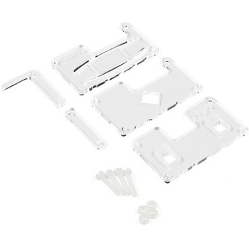
MI:pro Protector Case for micro:bit V2
SPARKFUN¥2,398税込¥2,6381個33日以内出荷Description。This MI:pro Protector Case for the BBC micro:bit has been designed to work with both the original micro:bit V1 and the micro:bit V2. These cases feature a four-layer construction style with ability to mount a 2xAAA battery pack to the back of the case while still providing access to all buttons and ports on the micro:bit. Though these cases do protect the micro:bit astoundingly well, the biggest benefit of using the MI:pro is to not accidentally short out the pads on the back of the micro:bit.。Construction is simple, requiring only a small flathead screwdriver(at most), and involves layering each plate on top of one another around the micro:bit and screwing it into place. Luckily, the MI:pro Protector case enables easy access to the edge pins at the bottom of the micro:bit, allowing it to still be plugged into an edge connector found on many of our carrier boards. The only board that cannot be used in conjunction with the MI:pro case is the SparkFun gamer:bit due to its edge connector being located in the center of the board.。Note:The MI:pro Protector case only includes the parts found in the Includes Tab. This case does。NOT。include a micro:bit, power source or mounting screws. These items will need to be purchased separately.。Features。Dimensions:Length:65mm.。Width:37mm.。Depth(without screws):12mm.。Depth(with screws):18.5mm.。Provides excellent protection to the BBC micro:bit whilst allowing access to the bottom pins.。Full access to the A and B buttons on the BBC micro:bit.。Attach a battery cage to the rear of the case with the supplied sticky fixer.。Full access to pins and connections including the micro USB connector.。Clear case material shows the on-board LEDs in perfect clarity.。The case is compatible with versions 1 and 2 of the micro:bit.。When used in conjunction with a battery holder, micro:bit projects can be fully mobile.アズワン品番67-0426-13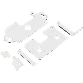
MI:pro Mountable Case for micro:bit V2
SPARKFUN¥1,998税込¥2,1981個33日以内出荷Description。The Mountable MI:pro is a simple and compact protective case for the micro:bit. This case has been specifically designed with portability and expansion in mind and is compatible with both the original micro:bit V1 and the micro:bit V2. These cases feature a three-layer construction style with ability to wall-mount the whole assembly onto any surface you want while still providing access to all buttons and ports on the micro:bit. Though these cases do feature wall-mountable tabs, the biggest benefit of using a case is to not accidentally short out the pads on the back of the micro:bit.。Construction is simple, requiring only a small flathead screwdriver, and involves layering each plate on top of one another around the micro:bit and screwing it into place. Luckily, the MI:pro case enables easy access to the edge pins at the bottom of the micro:bit, allowing it to still be plugged into an edge connector found on many of our carrier boards. The only board that cannot be used in conjunction with the MI:pro case is the SparkFun gamer:bit due to its edge connector being located in the center of the board.。Note:The MI:pro case only includes the parts found in the Includes Tab. This case does NOT include a micro:bit, power source or mounting screws. These items will need to be purchased separately.。Features。Dimensions:Length(minus the mounting brackets on the side):65mm.。Length(with the mounting brackets on the side):91mm.。Width:37mm.。Depth(without screws):9mm.。Depth(with screws):14mm.。Provides excellent protection to the BBC micro:bit whilst allowing access to the bottom pins.。Full access to the A and B buttons on the BBC micro:bit.。The mounting points allow you to fix the micro:bit to a surface for sturdy and more permanent installations.。Full access to pins and connections including the micro USB connector.。Clear case material shows the on-board LEDs in perfect clarity.。The case is compatible with versions 1 and 2 of the micro:bit.アズワン品番67-0426-14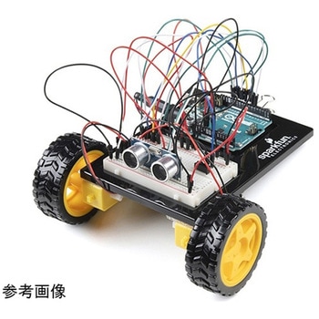
SparkFun Inventor's Kit for Arduino Uno - v4.1
SPARKFUN¥34,980税込¥38,4781個33日以内出荷。Description。The SparkFun Inventor's Kit(SIK)for Arduino Uno is a great way to get started with programming and hardware interaction with the Arduino programming language. The SIK includes everything you need to complete five overarching projects consisting of 16 interconnected circuits that teach everything from blinking an LED to reading sensors. The culminating project is your very own autonomous robot! No previous programming or electronics experience is required to use this kit.。The online guide contains step-by-step instructions with circuit diagrams and hookup tables for building each project and circuit with the included parts. Full example code is provided, new concepts and components are explained at point of use, and troubleshooting tips offer assistance if something goes wrong.。The kit does not require any soldering and is recommended for beginners ages 10 and up who are looking for an Arduino starter kit. For SIK version 4.1 we took an entirely different approach to teaching embedded electronics. In previous versions of the SIK, each circuit focused on introducing a new piece of technology. With SIK v4.1, components are introduced in the context of the circuit you are building, and each circuit builds upon the last, leading up to a project that incorporates all of the components and concepts introduced throughout the guide. With new parts and a completely new strategy, even if you've used the SIK before, you're in for a brand-new experience!。This version of the SIK replaces the SparkFun RedBoard Qwiic with the Arduino Uno(SMD version)and comes without the SIK guidebook and carrying case. With these components being swapped and removed, we were able to reduce the overall size and weight of the kit, making shipping cheaper and easier for anyone ordering internationally.。Note:As stated above, this SIK does NOT include a carrying case or print guidebook.。Get Started With the SparkFun Inventor's Kit v4.1 Experiment Guide。Examples。Project 1:Light。Circuit 1A:Blinking an LED。Circuit 1B:Potentiometer。Circuit 1C:Photoresistor。Circuit 1D:RGB Night-Light。Project 2:Sound。Circuit 2A:Buzzer。Circuit 2B:Digital Trumpet。Circuit 2C:"Simon Says" Game。Project 3:Motion。Circuit 3A:Servo Motors。Circuit 3B:Distance Sensor。Circuit 3C:Motion Alarm。Project 4:Display。Circuit 4A:LCD "Hello, World!"。Circuit 4B:Temperature Sensor。Circuit 4C:"DIY Who Am I?" Game。Project 5:Robot。Circuit 5A:Motor Basics。Circuit 5B:Remote-Controlled Robot。Circuit 5C:Autonomous Robotアズワン品番67-0424-34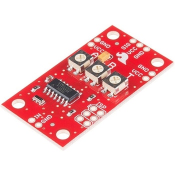
SparkFun Servo Trigger - Continuous Rotation
SPARKFUN¥4,898税込¥5,3881個33日以内出荷。Description。The SparkFun Continuous Rotation(CR)Servo Trigger is a small robotics board that simplifies the control of hobby RC servo motors. When an external switch or logic signal changes state, the CR Servo Trigger is able to tell an attached servo motor to move from position A to position B. To use the CR Servo Trigger, you simply connect a hobby servo and a switch, then use the on-board potentiometers to adjust the start/stop positions and the transition time. You can use a hobby servo in your projects without having to do any programming!。When we introduced the original Servo Trigger, we mentioned that it could be reprogrammed to be more useful with continuous rotation servo motors. But reprogramming the firmware is somewhat tedious, and users asked for a Servo Trigger preprogrammed with the continuous rotation logic. With this little board you will be provided an easy way to deploy continuous rotation servos into your projects!。The heart of the CR Servo Trigger is an Atmel ATtiny84 microcontroller, running a small program that implements the servo control features designed for continuous rotation servos. On board each of these CR Servo Triggers you will find three potentiometers:"A" sets the position the servo sits in while the switch is open, "B" sets the position the servo moves to when the switch is closed, and "T" sets the time it takes to get from A to B and back.。Compared with a servo motor, the CR Servo Trigger board draws very little current, roughly 5mA at 5V. Be sure to note that if you're using the CR Servo Trigger to control your motor, the absolute maximum supply voltage that should be applied is 5.5 VDC. Additionally, the SparkFun CR Servo Trigger is designed to make it easy to daisy chain boards - you can simply connect the VCC and GND pads on adjacent boards to each other.。Note:This idea originally came from our friend in the Oakland area, CTP. If you see him, please give him a high-five for us.。SparkFun CR Servo Trigger Hookup Guide。Features。Recommended Voltage:5VDC。Max Voltage:5.5VDC。Current Draw:5mA。Control Continuous Rotation Servos。Three Control Settings。A - sets the position the servo sits in while the switch is open。B - sets the position the servo moves to when the switch is closed。C - sets the time it takes to get from A to B and back。Easy Control with Potentiometers。Configurable Input Polarity。Configurable Response Mode。Compatible with Analog Servos。ISP Header Pins Available for Reprogramアズワン品番67-0429-21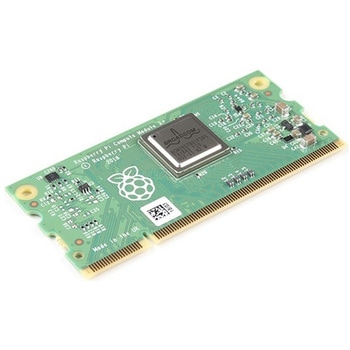
Raspberry Pi Compute Module 3+ Lite
SPARKFUN¥10,980税込¥12,0781個33日以内出荷Description。The Raspberry Pi Compute Module 3+ Lite contains the guts of a Raspberry Pi 3 Model B+(the BCM2837 processor and 1GB LPDDR2 RAM). This module allows a designer to leverage the Raspberry Pi hardware and software stack in their own custom systems and form factors. In addition this module has extra IO interfaces over and above what is available on the Raspberry Pi model A/B boards, opening up more options for the designer.。This is all integrated onto a small(67.6mm×31mm)board that fits into a standard DDR2 SODIMM connector. You get the full flexibility of the BCM2837 SoC(which means that many more GPIOs and interfaces are available than with a standard Raspberry Pi), and designing the Module into a custom system should be relatively straightforward because all the tricky bits have been put onto the Module itself.。The CM3+ Lite product is the same as CM3+ except the eMMC Flash is not fitted, and the SD/eMMC interface pins are available for the user to connect their own SD/eMMC device. Note that the CM3+ is electrically identical and, with the exception of higher CPU z-height, physically identical to the legacy CM3 products.。Note:The CM3+ modules require a software/firmware image dated November 2018 or newer to function correctly.。Features。Broadcom BCM2837B0, Cortex-A53(ARMv8)64-bit SoC @ 1.2GHz。1GB LPDDR2 SDRAM。Operating Supply Voltage:1.8V, 3.3V。Minimum Operating Temperature:-25C。Maximum Operating Temperature:+80C。HDMI, MIPI, USB, and GPIO interfaces on edge connectorアズワン品番67-0423-17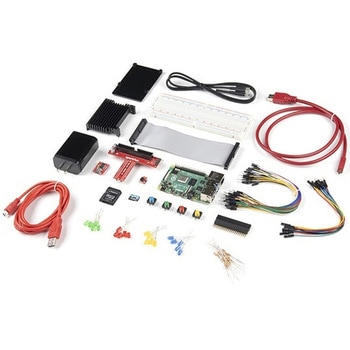
SparkFun Raspberry Pi 4 Hardware Starter Kit - 4GB
SPARKFUN¥56,980税込¥62,6781個33日以内出荷Description。The Raspberry Pi 4 Hardware Starter Kit provides a solid set of parts and instruction for working with the Raspberry Pi 4 in a more hardware-centric manner. While the Raspberry Pi isn't typically considered a go-to for hardware projects, its I/O pins hold a lot of benefits that you can use for a variety of applications. This kit covers the basics like using LEDs, and Buttons while providing a solid set of parts for working with any other hardware I/O and the 40-pin header. In addition, we've included all the parts needed for getting the Raspberry Pi 4 up and running whether it's on its own, or using a monitor(not included). The new 64GB MicroSD cards keep read/write commands running super fast, too.。Most of the contents of the kit rely on the use of the 2x20, 40-pin header, so we've included a special extender to allow you to plug in the ribbon cable while using the provided heatsink case. We've also included a Qwiic Shim for easily working with I2C based Qwiic boards with the Pi. No soldering is required for this kit!。Note:This variation includes the 4GB RAM option for the Raspberry Pi 4.。Get Started with the Raspberry Pi 4 Model B Guideアズワン品番67-0424-46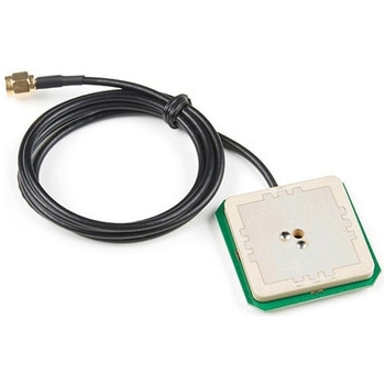
GPS/GNSS Embedded Antenna - 1m SMA
SPARKFUN¥29,980税込¥32,9781個33日以内出荷Description。This tri-band GNSS antenna is ideal for GPS L1, GLONASS L1, and Beidou B2 reception. At 45x45mm it is a。large。ceramic antenna with an incredible 38dB LNA gain.。This antenna works well with the GPS-RTK providing reception of Beidou satellites where other more basic GPS antennas cannot. We've chosen to have the antenna manufactured without an enclosure to decrease the weight(45g including cable)making this antenna more ideal for rover and quad-copter applications. Additionally, the cable length has been reduced to 1m to reduce weight and to make a more clean installation.。We recommend this antenna for RTK use when combined with the ground plate. This antenna is ideal for advanced raw, RTK, and post-processed measurements of GPS, GLONASS, and Beidou constellations. If all you need is GPS and GLONASS(basic GNSS)consider our lower cost magnetic mount GNSS antenna.。Antenna is terminated with a standard SMA connector. Check out the related items below for any conversion cables you may need.。Features。Dimensions:45x45x9mm。Weight:45g including 1m cable。Frequency Range:1558 - 1615MHz。LNA Voltage:3.3 to 15VDC。Primary Antenna Gain:4dB。LNA Gain:38dB。LNA Current:<= 35mA。Termination Connector:SMA。Impedance:50Ω。Right hand polarization。Cable Length:1 meterアズワン品番67-0423-73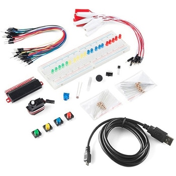
SparkFun Inventor's Kit Bridge Pack for micro:bit
SPARKFUN¥15,980税込¥17,5781個33日以内出荷Description。Do you own micro:bit or micro:bit Go Bundle and want to expand your skills with the new microcontroller? You are in luck! The SparkFun Inventor's Kit Bridge Pack for micro:bit was designed to provide you with an easy way to transform your m:b into full fledged learning kit! Each Bridge Pack includes all of the parts found in the SIK for micro:bit that aren't included with the Go Bundle. With the SIK Bridge Pack for micro:bit you will be able to complete circuits that will teach you how to read sensors, move motors, build Bluetooth(R)devices and more.。The micro:bit is pocket-sized computer that lets you get creative with digital technology. Between the micro:bit and our shield-like bit boards you can do almost anything while coding, customizing and controlling your micro:bit from almost anywhere! You can use your micro:bit for all sorts of unique creations, from robots to musical instruments and more. At half the size of credit card, this versatile board has vast potential!。Note:The Bridge Pack is NOT full SparkFun Inventor's Kit and only includes the parts to complement micro:bit Go Bundle or standalone board. That also means that this kit does。not。include micro:bit, which will need to be purchased separately.。Get started with the micro:bit SIK Experiment Guide。Examples。Circuit 0:Hello, micro:bit!。Circuit 1:Blinking an LED。Circuit 2:Reading Potentiometer。Circuit 3:Reading Photoresistor。Circuit 4:Driving an RGB LED。Circuit 5:Reading an SPDT Switch。Circuit 6:Reading Button Press。Circuit 7:Reading the Temperature Sensor。Circuit 8:Using Servo Motor。Circuit 9:Using Buzzer。Circuit 10:Using the Accelerometer。Circuit 11:Using the Compassアズワン品番67-0424-21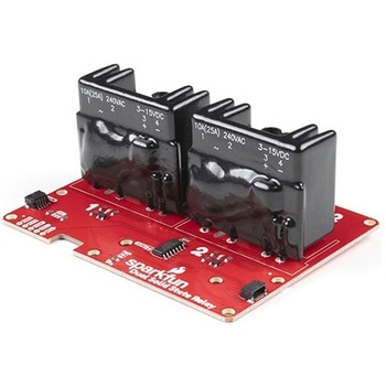
SparkFun Qwiic Dual Solid State Relay
SPARKFUN¥39,980税込¥43,9781個33日以内出荷Description。The SparkFun Qwiic Dual Solid State Relay is a power delivery board that allows users to switch two AC loads from a low power microcontroller using the SparkFun Qwiic connect system. The board features two 25A/250VAC solid state relays that utilize the Zero Cross Trigger method so you can toggle two loads on a 60Hz AC carrier signal on and off up to 120 times per second!。An ATTiny84 acts as the "brain" of the SparkFun Qwiic Dual Solid Relay to accept I2C commands to toggle the two relays as well as a few other special commands. The I2C address of the ATtiny84A is software configurable so, if you have a seriously big power project in mind, you could daisy chain over 100 Qwiic Dual Solid State Relays.。Messing with such high voltage is dangerous! We've included many safety precautions onto the PCB including ground isolation between the relay and other circuitry and a milled out area isolating each side of AC. However, with all the safety precautions included with the SparkFun Qwiic Dual Solid State Relay, this is still a power accessory for users who are experienced around, and knowledgeable about high AC voltage. If you're not comfortable with handling AC voltage in this way, you may want to check out the IoT Power Relay instead.。Note:The relays are rated for a max of 25A with forced air cooling. If you do not have forced air cooling, 10A max through the relays is recommended.。The SparkFun Qwiic connect system is an ecosystem of I2C sensors, actuators, shields and cables that make prototyping faster and less prone to error. All Qwiic-enabled boards use a common 1mm pitch, 4-pin JST connector. This reduces the amount of required PCB space, and polarized connections mean you can't hook it up wrong.。Get Started with the SparkFun Qwiic Dual Solid State Relay Guide。Features。Operating Voltage:2.5-3.6V(3.3V recommended)。I2C Address:0x0A(Default)0x0B(Alternate via jumper select)。Load Voltage Range:12-280VAC。Max Current(Through Relay):25A(240VAC with forced air cooling)。Zero Cross Trigger。Normally Open Circuit Only。2x Qwiic Connectorアズワン品番67-0421-58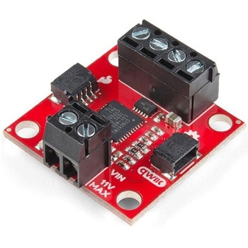
SparkFun Qwiic Motor Driver
SPARKFUN¥6,698税込¥7,3681個33日以内出荷。Description。The SparkFun Qwiic Motor Driver takes all the great features of the Serial Controlled Motor Driver(SCMD)and miniaturizes them, adding Qwiic ports for plug and play functionality. Boasting the same 4245 PSOC and 2-channel motor ports as the SCMD, the SparkFun Qwiic Motor Driver is designed to communicate over I2C to make setting up your next robotic project as fast and easy as possible! Utilizing our handy Qwiic system and screw terminals for motor and power hook-up, no soldering is required to connect it to the rest of your system.。With 1.2A steady state drive per channel(1.5A peak)and 127 levels of DC drive strength, this little Qwiic board is perfect for your small DC motor driver needs. Since the Qwiic Motor Driver is a 3.3V logic device, you'll need to use a logic level converter to interface to 5V.。The I2C address of the Qwiic Motor Driver is 0x5D and is jumper selectable to 0x58, 0x59, 0x5A, 0x5B, ... 0x63.。The SparkFun Qwiic Connect System is an ecosystem of I2C sensors, actuators, shields and cables that make prototyping faster and less prone to error. All Qwiic-enabled boards use a common 1mm pitch, 4-pin JST connector. This reduces the amount of required PCB space, and polarized connections mean you can't hook it up wrong.。Need a custom board? This component can be found in SparkFun's A La Carte board builder. You can have a custom design fabricated with this component - and your choice of hundreds of other sensors, actuators and wireless devices - delivered to you in just a few weeks.。Get Started With the Qwiic Motor Driver Hookup Guide。Features。1.5 A peak drive per channel, 1.2 A steady state。Operates from 3 to 11 Volts with 12V absolute max。3.3V default VCC and logic。127 levels of DC drive strength.。Controllable by I2C or TTL UART signals。Direction inversion on a per motor basis。Global Drive enable。Exposed small heat sink shape。Several I2C addresses, default UART bauds available。Adjustable I2C Address:0x5D Default。2x Qwiic Connectors。。Documents。Schematic。Eagle Files。Board Dimensions。Hookup Guide。Arduino Library。Python Module。Github Hardware Repoアズワン品番67-0426-33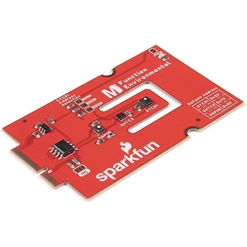
SparkFun MicroMod Environmental Function Board
SPARKFUN¥44,980税込¥49,4781個33日以内出荷Description。The SparkFun MicroMod Environmental Function Board adds additional sensing options to the MicroMod Processor Boards. This Function Board includes three sensors to monitor air quality(SGP40), humidity temperature(SHTC3), and CO2 concentrations(STC31)in your indoor environment. To make it even easier to use, all communication is over the MicroMod's I2C bus!。The SGP40 measures the quality of the air in your room or house. The SGP40 uses a metal oxide(MOx)sensor with a temperature controlled micro hotplate and provides a humidity-compensated volatile organic compound(VOC)based indoor air quality signal. Both the sensing element and VOC Algorithm feature an unmatched robustness against contaminating gases present in real world applications enabling a unique long term stability as well as low drift and device to device variation.。The SHTC3 is a highly accurate digital humidity and temperature sensor. The SHTC3 uses a capacitive humidity sensor with a relative humidity measurement range of 0 to 100% RH and bandgap temperature sensor with a temperature measurement range of -40℃ to 125℃. The SHTC3 builds on the success of their SHTC1 sensor with higher accuracy(±2% RH, ±0.2℃)than its predecessor, enabling greater flexibility.。The STC31 measures CO2 concentrations based on thermal conductivity and has two CO2 measurement ranges:0 to 25 vol%; and 0 to 100 vol%. The measurement repeatability is 0.2 vol%, with a stability of 0.025 vol% / ℃. The measurement accuracy depends on the measurement range:0.5 vol% + 3% measured value; 1 vol% + 3% measured value. Using measurements from the SHTC3, the STC31 is able to provide humidity-compensated measurements together with improved temperature compensation. The STC31 can compensate for atmospheric pressure too - which is handy if, like us, you're up in the mountains!。The outstanding performance of these three sensors is based on Sensirion's patented CMOSens(R)technology, which combines the sensor element, signal processing, and digital calibration on a small CMOS chip. The well-proven CMOS technology is perfectly suited for high-quality mass production and is the ideal choice for demanding and cost-sensitive OEM applications.。Utilizing our handy M.2 MicroMod connector, no soldering is required to connect it to your system. Simply match up the key on your processor and function board's beveled edge connector to their respective key on the M.2 connector, then secure them to the main board with screws. The MicroMod Environmental Function Board can then be read via the I2C port. The board is equipped with the AP2112 3.3V voltage regulator, I2C pull-up resistors, power LED, jumper to disable the LED, and jumpers for alternative STC31 addresses.。Note:A MicroMod Processor and Main Board are not included with this MicroMod Environmental Function Board. These boards will need to be purchased separately.。MicroMod is a modular interface ecosystem that connects a microcontroller "processor board" to various "carrier board" peripherals. Utilizing the M.2 standard, the MicroMod standard is designed to easily swap out processors and function boards on the fly. Pair a specialized carrier board for the project you need with your choice of compatible processor!。Get Started with the MicroMod Environmental Function Board。Features。Input voltage range。2.5V to 6.0V。Typ.。5V。via Main Board's USB connector。Typ.。~3.7V to 4.2V。via Main Board's LiPo battery Connector。I/O voltage。3.3V。AP2112 3.3V voltage regulator(rated 600mA)。Power LED。I2C pull-up resistors。Sensirion SGP40 Air Quality Sensor。Uses I2C interface。Address:0x59(default)。Operating voltage range。1.7V to 3.6V(Typ.。3.3V。)。Operating temperature range。-20℃ to +55℃。Typical current consumption。2.6mA。during continuous operation(at 3.3V)。34μA。when idle(heater off)。Output signal。Digital raw value(SRAW):0 - 65535 ticks。Digital processed value(VOC Index):0 - 500 VOC index points。Switch-on behavior。Time until reliably detecting VOC events:<60s。Time until specifications are met:<1h。Recommended sampling interval。VOC Index:1s。SRAW:0.5s - 10s(Typ. 1s)。Sensirion SHTC3 Humidity and Temperature Sensor。Uses I2C interface。Address:0x70(default, non-configurable)。Operating voltage range。1.62V - 3.6V(Typ.。3.3V。)。Operating temperature range。-40℃ to +125 ℃。Relative Humidity。Measurement range:0% to 100%。Typical accuracy:±2 %RH。Resolution:0.01 %RH。Temperature。Measurement range:-40℃ to +125 ℃。Typical accuracy:±0.2 ℃。Resolution:0.01 ℃。Typical current consumption(varies based on mode)。4.9μA to 430μA(Normal Mode)。0.5μA to 270μA(Low Power Mode)。Allows the STC31 to compensate for humidity and temperature。Sensirion STC31 CO2 Sensor。Uses I2C interface。Addresses:0x29(default)。, 0x2A, 0x2B, 0x2C。Operating voltage range。2.7V to 5.5V(Typ.。3.3V。)。Operating temperature range。-20 ℃ to +85 ℃。Calibrated for CO2 in N2 and CO2 in air。Measurement ranges。0 to 25 vol% in N2。0 to 100 vol% in air。Accuracy。0.5 vol% + 3% measured value in N2。1 vol% + 3% measured value in air。Concentration and temperature resolution:16-bit。Repeatability:0.2 vol%。Temperature stability:0.025 vol% / ℃。Start-up time:14 ms。Thermal conductivity sensor provides calibrated gas concentration and temperature output。Jumpers。PWR LED。I2C pull-up resistors。STC31 address selection。Note:The I2C addresses that are reserved for each sensor is 0x59(SGP40), 0x70(SHTC3), 0x29(STC31). A multiplexer/Mux is required to communicate to multiple SHTC3 sensors on a single bus. The SHTC3 uses the same address as the Qwiic Mux(0x70). For advanced users that are using multiple SHTC3's with the Qwiic Mux, you will need to adjust the Qwiic Mux's default address.アズワン品番67-0427-60