カテゴリ
- 学童・教育用品(29)
- 制御機器(1)
絞り込み
ブランド
- SPARKFUN
- 三菱ふそう(59)
- DBLTACT(18)
- 沖データ(OKI)(14)
- RS PRO(12)
- メディアカバーマーケット(9)
- AMPHENOL(8)
- 沖電気工業(7)
- ベクトン・ディッキンソン(7)
- ホンダ(6)
- ASUS(エイスース)(6)
- エレコム(5)
- オーム電機(5)
- SKF(日本エスケイエフ)(4)
- BOSE(ボーズ)(4)
- Anker(アンカー)(4)
- Canon(3)
- I ・O DATA(アイ・オー・データ)(2)
- 3M(スリーエム)(2)
- ブランドをもっと見る
「blt c」の検索結果
 Logitech C270 Webcam - USB 2.0SPARKFUN
¥16,980税込¥18,678
1個
33日以内出荷
Description。This is the Logitech C270 Webcam. With a sleek compact look and a black finish, this is not just for looks. This economical choice provides a 720p/30FPS HD resolution in a 16:9 widescreen format. The Logitech C270 webcam is compatible with most major messaging applications like Skype, Windows Live Messenger, Yahoo Messenger and more, giving you a wide selection of use.。Fluid Crystal technology provides smoother videos, sharper pictures, richer colors and clearer sound in real-world conditions. With the automatic light correction, even if you make a video call in dim or poorly backlit settings, the camera will intuitively adjust to produce the best possible image.。The built-in noise-reducing mic makes sure your voice comes across clearly, even if you're in busy surroundings. This flexible webcam comes with a universal clip for mounting so you can either attach it securely to your screen or sit it on a shelf.。Features。USB port。Max Resolution - 720p/30fps。16:9 Widescreen。Photo Resolution - 3MP。Focus Type - Fixed focus 40cm and beyond。Lens Type - Plastic。Auto Light Correction。Built-in mic with noise cancellation - mono。Field of View 60°
アズワン品番67-0427-16
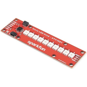 SparkFun Qwiic LED Stick - APA102CSPARKFUN
¥3,500税込¥3,850
1個
33日以内出荷
Description。The SparkFun Qwiic LED Stick features ten addressable APA102 LEDs, making it easy to add full color LED control using I2C. Write to individual LEDs to display a count in binary, or write to the whole strip for cool lighting effects. You can even add more LEDs to the end if you need to. We've written an Arduino library and Python package that take care of the I2C and communication to the LEDs so all you have to do is decide what color each LED should be.。The LED Stick has a default I2C address of 0x23 but can be changed with a simple command, allowing you to control up to 100 LEDs(10 Qwiic LED Sticks)on a single bus! The address can also be changed to 0x22 by closing the solder jumper on the back of the board.。This board is one of our many Qwiic compatible boards! Simply plug and go. No soldering, no figuring out which is SDA or SCL, and no voltage regulation or translation required!。Warning:Using a lot of LEDs can draw a lot of current. Make sure to consider the power limits of your setup. If you expect your LED chain to draw more than 600mA of current, connect your external supply directly to VLED. Closing the jumper from VLED to VCC will add a 4.7uF decoupling capacitor.。The SparkFun Qwiic Connect System is an ecosystem of I2C sensors, actuators, shields and cables that make prototyping faster and less prone to error. All Qwiic-enabled boards use a common 1mm pitch, 4-pin JST connector. This reduces the amount of required PCB space, and polarized connections mean you can't hook it up wrong.。Get Started with the Qwiic LED Stick Guide。Features。10x APA102C addressable LEDs driven by an ATTiny85。Default I2C Address:0x23(Adjustable to 0x22 via Jumper)。2x Qwiic Connectors
アズワン品番67-0421-83
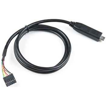 FTDI to USB-C Cable - 5V VCC-3.3V I/OSPARKFUN
¥7,998税込¥8,798
1個
33日以内出荷
。Description。USB C is quickly becoming more and more prominent in the maker community because, let's be honest, who likes trying three times to insert USB into a port? This FTDI cable is a USB C to Serial converter which allows for a simple way to connect TTL interface devices to USB. Each 26AWG cable is one meter in length with the USB C side protected by a 2in enclosure.。The FTDI cable is designed around an RS232, which is housed in a USB C connector. The other side of the cable is terminated with a 0.1" pitch, 6-pin connector with the following pinout:RTS(Green), RX(Yellow), TX(Orange), VCC 5V(Red), CTS(Brown), GND(Black). This FTDI to USB C Cable is also capable of handling high voltages up to 300V max.。There are pros and cons to the FTDI Cable vs the FTDI Basic. The FTDI Basic has great LED indicators, but requires a Mini-B cable. The FTDI Cable is well protected against the elements, but is large and cannot be embedded into a project as easily. The FTDI Basic uses DTR to cause a hardware reset where the FTDI cable uses the RTS signal.
アズワン品番67-0420-42
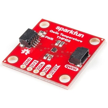 SparkFun Digital Temperature Sensor - TMP102 QwiicSPARKFUN
¥2,398税込¥2,638
1個
33日以内出荷
Description。We all like to know the temperature, right? Well, with the SparkFun TMP102 Digital Temperature Sensor, we've made it just about as easy as it gets. Based on the original Digital Temperature Sensor Breakout TMP102, we've added Qwiic connectors to bring this board into our plug-and-play Qwiic Ecosystem and added an address jumper instead of breaking out the address pin. However, we still have broken out 0.1"-spaced pins in case you prefer to use breadboard.。The TMP102 itself is an easy-to-use digital temperature sensor from Texas Instruments. While some temperature sensors use an analog voltage to represent the temperature, the TMP102 uses the I2C bus of the Arduino to communicate the temperature.。The TMP102 is capable of reading temperatures to resolution of 0.0625℃, and is accurate up to 0.5℃. The breakout has built-in 4.7kΩ pull-up resistors for I2C communications and runs from 1.4V to 3.6V. I2C communication uses an open drain signaling, so there is no need to use level shifting.。The SparkFun Qwiic Connect System is an ecosystem of I2C sensors, actuators, shields and cables that make prototyping faster and less prone to error. All Qwiic-enabled boards use common 1mm pitch, 4-pin JST connector. This reduces the amount of required PCB space, and polarized connections mean you can't hook it up wrong.。Get Started with the Qwiic TMP102 Digital Temperature Sensor Guide。Features。Uses the I2C interface。I2C Address:0x48 by default。(Three additional addresses available, as well)。12-bit, 0.0625℃ resolution。Typical temperature accuracy of ±0.5℃。3.3V sensor。Supports up to four TMP102 sensors on the I2C bus at time。2x Qwiic Connectors
アズワン品番67-0427-17
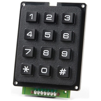 SparkFun Qwiic Keypad - 12 ButtonSPARKFUN
¥4,198税込¥4,618
1個
33日以内出荷
Description。Keypads are very handy input devices, but who wants to tie up seven GPIO pins, wire up handful of pull-up resistors, and write firmware that wastes valuable processing time scanning the keys for inputs? The SparkFun Qwiic Keypad comes fully assembled and makes the development process for adding 12 button keypad easy. No voltage translation or figuring out which I2C pin is SDA or SCL, just plug and go! Utilizing our handy Qwiic system, no soldering is required to connect it to the rest of your system. However, we still have broken out 0.1"-spaced pins in case you prefer to use breadboard.。Each of the keypad's 12 buttons has been labeled 1, 2, 3, 4, 5, 6, 7, 8, 9, 0, *, and and has been formatted to into the same layout as telephone keypad with each keypress resistance ranging between 10 and 150 Ohms. The Qwiic Keypad reads and stores the last 15 button presses in First-In, First-Out(FIFO)stack, so you don't need to constantly poll the keypad from your microcontroller. This information, then, is accessible through the Qwiic interface. The SparkFun Qwiic Keypad even has software configurable I2C address so you can have multiple I2C devices on the same bus.。NOTE:The I2C address of the Qwiic Keypad is 0x4B and is jumper selectable to 0x4A(software-configurable to any address). multiplexer/Mux is required to communicate to multiple Qwiic Keypad sensors on single bus. If you need to use more than one Qwiic Keypad sensor consider using the Qwiic Mux Breakout.。The SparkFun Qwiic connect system is an ecosystem of I2C sensors, actuators, shields and cables that make prototyping faster and less prone to error. All Qwiic-enabled boards use common 1mm pitch, 4-pin JST connector. This reduces the amount of required PCB space, and polarized connections mean you can't hook it up wrong.。Get Started with the SparkFun Qwiic Keypad Hookup Guide。Features。Software Selectable Slave Address。Low Power ATtiny85 controller。Button Presses w/ Time Stamp。Default I2C Address:0x4B。2x Qwiic Connector
アズワン品番67-0421-41
 SparkFun Qwiic MultiPortSPARKFUN
¥999税込¥1,099
1個
33日以内出荷
Description。Qwiic is a very efficient way to quickly prototype an idea but not all Qwiic-enabled devices have two ports. The SparkFun Qwiic MultiPort adds additional ports to boards that have only one Qwiic port on the I2C bus. Once added, you can use
アズワン品番67-0420-16
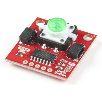 SparkFun Qwiic Button - Green LEDSPARKFUN
¥1,698税込¥1,868
1個
33日以内出荷
Description。Buttons are an easy and tactile way to interface with your project, but why would you want to deal with debouncing, polling, and wiring up pull-up resistors? The Qwiic Button with built-in green LED simplifies all of those nasty worries away into an easy to use I2C device! Utilizing our Qwiic Connect System, using the button is as simple as connecting cable and loading up some pre-written code!。If you need multiple buttons for your project, fear not! Each button has configurable I2C address, so you can daisy-chain multiple buttons over Qwiic and still address each one individually. We've got an example in our Arduino library that provides super-easy way to configure your Qwiic Button to whatever I2C address you desire. You can download the library through the Arduino library manager by searching 'SparkFun Qwiic Button' or you can get the GitHub repo as .zip file and install the library from there.。In addition to handling blinking and debouncing, the Qwiic Button has configurable interrupts that can be configured to activate upon button press or click. We've also taken the liberty of implementing FIFO queue onboard the Qwiic Button where it keeps an internal record of when the button was pressed. This means that code on your microcontroller need not waste valuable processing time checking the status of the button but instead can run small function whenever the button is pressed or clicked! For more information on interrupts check out our guide here!。The SparkFun Qwiic Connect System is an ecosystem of I2C sensors, actuators, shields and cables that make prototyping faster and less prone to error. All Qwiic-enabled boards use common 1mm pitch, 4-pin JST connector. This reduces the amount of required PCB space, and polarized connections mean you can't hook it up wrong.。Get Started with the SparkFun Qwiic Button Guide。Features。12mm Green LED Button rated for 50mA。Built in LED can be configured for your desired level of blinkiness!。Each button has configurable I2C address。Configurable interrupts check out our guide here!。FIFO queue。Don't like the color green? Check out the SparkFun Qwiic Button Breakout and add another colored button!。Red LED Tactile Button。Blue LED Tactile Button。Green LED Tactile Button。White LED Tactile Button
アズワン品番67-0420-14
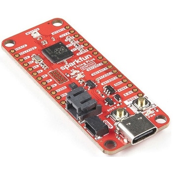 SparkFun Thing Plus - RP2040SPARKFUN
¥6,698税込¥7,368
1個
33日以内出荷
Description。The SparkFun Thing Plus - RP2040 is a low-cost, high performance board with flexible digital interfaces featuring the Raspberry Pi Foundation's RP2040 microcontroller. Besides the Thing Plus or。Feather。footprint(with 18 GPIO pins), the board also includes an SD card slot, 16MB(128Mbit)flash memory, a JST single cell battery connector(with a charging circuit and fuel gauge sensor), an addressable WS2812 RGB LED, JTAG PTH pins, four(4-40 screw)mounting holes, and our signature Qwiic connector.。The RP2040 contains two ARM Cortex-M0+ processors(up to 133MHz)and features:264kB of embedded SRAM in six banks。6 dedicated IO for SPI Flash(supporting XIP)。30 multifunction GPIO:Dedicated hardware for commonly used peripherals。Programmable IO for extended peripheral support。Four 12-bit ADC channels with internal temperature sensor(up to 0.5 MSa/s)。USB 1.1 Host/Device functionality。The RP2040 is supported with both C/C++ and MicroPython cross-platform development environments, including easy access to runtime debugging. It has UF2 boot and floating-point routines baked into the chip. While the chip has a large amount of internal RAM, the board includes an additional 16MB of external QSPI flash memory to store program code.。The SparkFun Qwiic Connect System is an ecosystem of I2C sensors, actuators, shields and cables that make prototyping faster and less prone to error. All Qwiic-enabled boards use a common 1mm pitch, 4-pin JST connector. This reduces the amount of required PCB space, and polarized connections mean you can't hook it up wrong.。Get Started With the Thing Plus RP2040 Hookup Guide。Features。SparkFun Thing Plus - RP2040 Features。Raspberry Pi Foundation's RP2040 microcontroller。16MB QSPI Flash Memory。JTAG PTH Pins。Thing Plus(or Feather)Form-Factor:18[1]x Multifunctional GPIO Pins[2]。Four available 12-bit ADC channels with internal temperature sensor(500kSa/s)。Up to eight 2-channel PWM。Up to two UARTs。Up to two I2C buses。Up to two SPI buses。USB-C Connector:USB 1.1 Host/Device functionality。2-pin JST Connector for a LiPo Battery。(not included)。500mA charging circuit。Qwiic Connector。Buttons:Boot。Reset。LEDs:PWR。- Red 3.3V power indicator。CHG。- Yellow battery charging indicator。25。- Blue status/test LED(。GPIO 25。)。WS2812。- Addressable RGB LED(。GPIO 08。)。Four Mounting Holes:4-40 screw compatible。Dimensions:2.3"×0.9"。RP2040 General Features。Dual Cortex M0+ processors, up to 133 MHz。264 kB of embedded SRAM in 6 banks。6 dedicated IO for QSPI flash, supporting execute in place(XIP)。30 programmable IO for extended peripheral support。SWD interface。Timer with 4 alarms。Real time counter(RTC)。USB 1.1 Host/Device functionality。Supported programming languages。MicroPython。C/C++。1.。Note:。GPIO 08。is not included in this count, as it passes through the WS2812 addressable RGB LED first.。GPIO 07。and。GPIO 23。are counted as a single GPIO because they are tied together.。2.。Note:The GPIO pins are programmable so you can reconfigure the pins! Check out the RP2040 datasheet for more information on the GPIO functionality.
アズワン品番67-0423-56
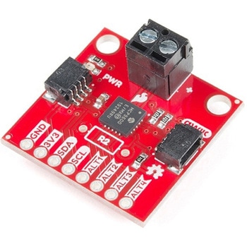 SparkFun Qwiic Thermocouple Amplifier - MCP9600 Screw TerminalsSPARKFUN
¥8,998税込¥9,898
1個
33日以内出荷
Description。The MCP9600 Breakout is a high accuracy Thermocouple Amplifier equipped with an I2C interface, accessed over our Qwiic system. Inside the chip are two temperature sensors, one for the thermocouple itself(the hot junction)and one for the chip itself(the cold junction). As a result, the MCP9600 can read both the ambient temperature and the temperature of whatever you're trying to measure! The MCP9600 can do both with a resolution of 0.0625℃, and an accuracy of ±1.5℃(worst-case). The MCP9600 Thermocouple Amplifier is one of our many Qwiic compatible boards! Simply plug and go. No soldering, no figuring out which is SDA or SCL, and no voltage regulation or translation required!。This version of the board comes equipped with screw terminals to allow for your own Thermocouple's wiring to be hooked up with the turn of a screw. This makes it perfect for a variety of applications, from measuring the temperature of your Crock-Pot to making sure your backyard induction furnace is up to temperature.。In addition, the MCP9600 has four on-board temperature alerts that you can configure! Instead of constantly polling the sensor over I2C, you can set a temperature limit to trigger an interrupt when the temperature reaches a certain value. This frees up your microcontroller and your I2C bus to do more important things. It's also possible to put the MCP9600 into alternate operation modes in order to save power. The sensor supports a burst mode, where it will take a specified number of samples, return the results, and then go to sleep. This low-power mode makes the MCP9600 perfect for portable applications!。We've written an Arduino library to help you get started quickly. You can download the library through the Arduino library manager by searching 'SparkFun MCP9600' or you can get the GitHub repo as a .zip file and install the library from there.。The SparkFun Qwiic Connect System is an ecosystem of I2C sensors, actuators, shields and cables that make prototyping faster and less prone to error. All Qwiic-enabled boards use a common 1mm pitch, 4-pin JST connector. This reduces the amount of required PCB space, and polarized connections mean you can't hook it up wrong.。Get Started with the Qwiic Thermocouple Amplifier。Features。Temperature Range of -200℃ to 1350℃。Four Onboard Temperature Alerts。Resolution of 0.0625℃。Screw Terminal Connector。ADDR Jumper for variable I2C Addresses(default address of 0x60)。2x Qwiic Connectors
アズワン品番67-0427-15
 SparkFun Qwiic Motor DriverSPARKFUN
¥6,698税込¥7,368
1個
33日以内出荷
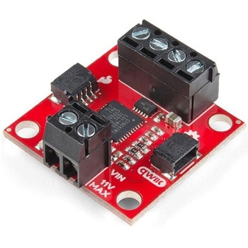
。Description。The SparkFun Qwiic Motor Driver takes all the great features of the Serial Controlled Motor Driver(SCMD)and miniaturizes them, adding Qwiic ports for plug and play functionality. Boasting the same 4245 PSOC and 2-channel motor ports as the SCMD, the SparkFun Qwiic Motor Driver is designed to communicate over I2C to make setting up your next robotic project as fast and easy as possible! Utilizing our handy Qwiic system and screw terminals for motor and power hook-up, no soldering is required to connect it to the rest of your system.。With 1.2A steady state drive per channel(1.5A peak)and 127 levels of DC drive strength, this little Qwiic board is perfect for your small DC motor driver needs. Since the Qwiic Motor Driver is a 3.3V logic device, you'll need to use a logic level converter to interface to 5V.。The I2C address of the Qwiic Motor Driver is 0x5D and is jumper selectable to 0x58, 0x59, 0x5A, 0x5B, ... 0x63.。The SparkFun Qwiic Connect System is an ecosystem of I2C sensors, actuators, shields and cables that make prototyping faster and less prone to error. All Qwiic-enabled boards use a common 1mm pitch, 4-pin JST connector. This reduces the amount of required PCB space, and polarized connections mean you can't hook it up wrong.。Need a custom board? This component can be found in SparkFun's A La Carte board builder. You can have a custom design fabricated with this component - and your choice of hundreds of other sensors, actuators and wireless devices - delivered to you in just a few weeks.。Get Started With the Qwiic Motor Driver Hookup Guide。Features。1.5 A peak drive per channel, 1.2 A steady state。Operates from 3 to 11 Volts with 12V absolute max。3.3V default VCC and logic。127 levels of DC drive strength.。Controllable by I2C or TTL UART signals。Direction inversion on a per motor basis。Global Drive enable。Exposed small heat sink shape。Several I2C addresses, default UART bauds available。Adjustable I2C Address:0x5D Default。2x Qwiic Connectors。。Documents。Schematic。Eagle Files。Board Dimensions。Hookup Guide。Arduino Library。Python Module。Github Hardware Repo
アズワン品番67-0426-33
 SparkFun Qwiic MicroPressure SensorSPARKFUN
¥24,980税込¥27,478
1個
33日以内出荷
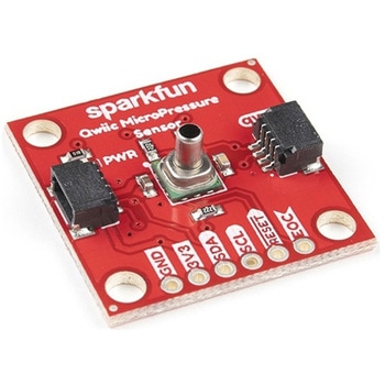
Description。The SparkFun Qwiic MicroPressure Sensor is a miniature breakout equipped with Honeywell's 25psi piezoresistive silicon pressure sensor. This MicroPressure Sensor offers a calibrated and compensated pressure sensing range of 60mbar to 2.5bar, easy to read 24 bit digital I2C output, and can be calibrated and compensated over a specific temperature range for sensor offset, sensitivity, temperature effects, and non-linearity using an on-board Application Specific Integrated Circuit(ASIC). With its ultra-low power consumption and Qwiic ports, you've got yourself a power packed little sensor!。Each Qwiic MicroPressure Sensor has a calibrated pressure sensing range from 1-25psi and a power consumption rate as low as 0.01mW typ. average power, 1Hz measurement frequency for ultimate portability. Used in multiple medical(blood pressure monitoring, negative pressure wound therapy), industrial(air braking systems, gas and water meters), and consumer uses(coffee machines, humidifiers, air beds, washing machines, dishwashers), the SparkFun Qwiic MicroPressure Sensor is a great addition to the SparkFun Qwiic ecosystem!。The SparkFun Qwiic Connect System is an ecosystem of I2C sensors, actuators, shields and cables that make prototyping faster and less prone to error. All Qwiic-enabled boards use a common 1mm pitch, 4-pin JST connector. This reduces the amount of required PCB space, and polarized connections mean you can't hook it up wrong.。Get Started with the SparkFun Qwiic MicroPressure Hookup Guide。Features。Pressure Type:Absolute。Operating Pressure:25psi(172.37kPa)。I2C Address:0x18。Accuracy:±0.25%。Voltage - Supply:1.8V-3.6V。Port Size:Male - 0.1"(2.5mm)Tube。Port Style:Barbless。Maximum Pressure:60psi(413.69kPa)。Compatible with a variety of liquid media。2x Qwiic Connectors
アズワン品番67-0427-25
 QWIIC 12BIT 4CHANNEL ADS1015SPARKFUN
¥5,498税込¥6,048
1個
33日以内出荷
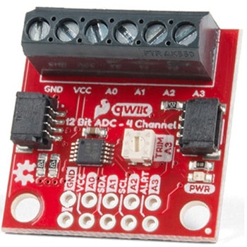
Description。A lot of the time you just need to add more analog inputs to solve a problem. It happens. The SparkFun Qwiic 12 Bit ADC can provide four channels of I2C controlled ADC input to your Qwiic enabled project. These channels can be used as single-ended inputs, or in pairs for differential inputs. What makes this even more powerful is that it has a programmable gain amplifier that lets you "zoom in" on a very small change in analog voltage(but will still effect your input range and resolution). Utilizing our handy Qwiic system, no soldering is required to connect it to the rest of your system. However, we still have broken out 0.1"-spaced pins in case you prefer to use a breadboard.。The ADS1015 uses its own internal voltage reference for measurements, but a ground and 3.3V reference are also available on the pin outs for users. This ADC board includes screw pin terminals on the four channels of input, allowing for solderless connection to voltage sources in your setup. It also has an address jumper that lets you choose one of four unique addresses(0x48, 0x49, 0x4A, 0x4B). With this, you can connect up to four of these on the same I2C bus and have sixteen channels of ADC. The maximum resolution of the converter is 12-bits in differential mode and 11-bits for single-ended inputs. Step sizes range from 125μV per count to 3mV per count depending on the full-scale range(FSR)setting.。We have included an onboard 10K trimpot connected to channel A3. This is handy for initial setup testing and can be used as a simple variable input to your project. But don't worry, we added an isolation jumper so you can use channel A3 however you'd like.。Note:The I2C address of the ADS1015 is 0x48 and is jumper selectable to 0x49, 0x4A, 0x4B. A multiplexer/Mux is required to communicate to multiple ADS1015 sensors on a single bus. If you need to use more than one ADS1015 sensor consider using the Qwiic Mux Breakout.。The SparkFun Qwiic connect system is an ecosystem of I2C sensors, actuators, shields and cables that make prototyping faster and less prone to error. All Qwiic-enabled boards use a common 1mm pitch, 4-pin JST connector. This reduces the amount of required PCB space, and polarized connections mean you can't hook it up wrong.。Get Started with the SparkFun Qwiic 12-Bit ADC Hookup Guide。Features。ADS1015。Operating Voltage(VDD):2.0V-5.5V。(Note:When powering with a Qwiic cable, the input range is only 3.3v)。Operating Temperature:-40℃ to 125℃。Operation Modes:Single-Shot, Continuous-Conversion(Default), and Duty Cycling。Analog Inputs:Measurement Type:Single-Ended(Default)。Input Voltage Range:GND to VDD。Full Scale Range(FSR):±.256V to ±6.114V(Default:2.048V)。Resolution:12-bit(Differential)or 11-bit(Single-Ended)。LSB size:0.125mV - 3mV(Default:1 mV)。Sample Rate:128 Hz to 3.3 kHz(Default:1600SPS)。Current Consumption(Typical):150μA-200μA。I2C Address:0x48(Default), 0x49, 0x4A, or 0x4B。Screw pin terminals for solderless connection to voltage sources。Four unique I2C addresses:0x48。0x49。0x4A。0x4B。2x Qwiic connection ports。Onboard 10K trimpot
アズワン品番67-0360-13
 SparkFun MicroMod Environmental Function BoardSPARKFUN
¥44,980税込¥49,478
1個
33日以内出荷
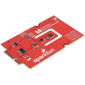
Description。The SparkFun MicroMod Environmental Function Board adds additional sensing options to the MicroMod Processor Boards. This Function Board includes three sensors to monitor air quality(SGP40), humidity temperature(SHTC3), and CO2 concentrations(STC31)in your indoor environment. To make it even easier to use, all communication is over the MicroMod's I2C bus!。The SGP40 measures the quality of the air in your room or house. The SGP40 uses a metal oxide(MOx)sensor with a temperature controlled micro hotplate and provides a humidity-compensated volatile organic compound(VOC)based indoor air quality signal. Both the sensing element and VOC Algorithm feature an unmatched robustness against contaminating gases present in real world applications enabling a unique long term stability as well as low drift and device to device variation.。The SHTC3 is a highly accurate digital humidity and temperature sensor. The SHTC3 uses a capacitive humidity sensor with a relative humidity measurement range of 0 to 100% RH and bandgap temperature sensor with a temperature measurement range of -40℃ to 125℃. The SHTC3 builds on the success of their SHTC1 sensor with higher accuracy(±2% RH, ±0.2℃)than its predecessor, enabling greater flexibility.。The STC31 measures CO2 concentrations based on thermal conductivity and has two CO2 measurement ranges:0 to 25 vol%; and 0 to 100 vol%. The measurement repeatability is 0.2 vol%, with a stability of 0.025 vol% / ℃. The measurement accuracy depends on the measurement range:0.5 vol% + 3% measured value; 1 vol% + 3% measured value. Using measurements from the SHTC3, the STC31 is able to provide humidity-compensated measurements together with improved temperature compensation. The STC31 can compensate for atmospheric pressure too - which is handy if, like us, you're up in the mountains!。The outstanding performance of these three sensors is based on Sensirion's patented CMOSens(R)technology, which combines the sensor element, signal processing, and digital calibration on a small CMOS chip. The well-proven CMOS technology is perfectly suited for high-quality mass production and is the ideal choice for demanding and cost-sensitive OEM applications.。Utilizing our handy M.2 MicroMod connector, no soldering is required to connect it to your system. Simply match up the key on your processor and function board's beveled edge connector to their respective key on the M.2 connector, then secure them to the main board with screws. The MicroMod Environmental Function Board can then be read via the I2C port. The board is equipped with the AP2112 3.3V voltage regulator, I2C pull-up resistors, power LED, jumper to disable the LED, and jumpers for alternative STC31 addresses.。Note:A MicroMod Processor and Main Board are not included with this MicroMod Environmental Function Board. These boards will need to be purchased separately.。MicroMod is a modular interface ecosystem that connects a microcontroller "processor board" to various "carrier board" peripherals. Utilizing the M.2 standard, the MicroMod standard is designed to easily swap out processors and function boards on the fly. Pair a specialized carrier board for the project you need with your choice of compatible processor!。Get Started with the MicroMod Environmental Function Board。Features。Input voltage range。2.5V to 6.0V。Typ.。5V。via Main Board's USB connector。Typ.。~3.7V to 4.2V。via Main Board's LiPo battery Connector。I/O voltage。3.3V。AP2112 3.3V voltage regulator(rated 600mA)。Power LED。I2C pull-up resistors。Sensirion SGP40 Air Quality Sensor。Uses I2C interface。Address:0x59(default)。Operating voltage range。1.7V to 3.6V(Typ.。3.3V。)。Operating temperature range。-20℃ to +55℃。Typical current consumption。2.6mA。during continuous operation(at 3.3V)。34μA。when idle(heater off)。Output signal。Digital raw value(SRAW):0 - 65535 ticks。Digital processed value(VOC Index):0 - 500 VOC index points。Switch-on behavior。Time until reliably detecting VOC events:<60s。Time until specifications are met:<1h。Recommended sampling interval。VOC Index:1s。SRAW:0.5s - 10s(Typ. 1s)。Sensirion SHTC3 Humidity and Temperature Sensor。Uses I2C interface。Address:0x70(default, non-configurable)。Operating voltage range。1.62V - 3.6V(Typ.。3.3V。)。Operating temperature range。-40℃ to +125 ℃。Relative Humidity。Measurement range:0% to 100%。Typical accuracy:±2 %RH。Resolution:0.01 %RH。Temperature。Measurement range:-40℃ to +125 ℃。Typical accuracy:±0.2 ℃。Resolution:0.01 ℃。Typical current consumption(varies based on mode)。4.9μA to 430μA(Normal Mode)。0.5μA to 270μA(Low Power Mode)。Allows the STC31 to compensate for humidity and temperature。Sensirion STC31 CO2 Sensor。Uses I2C interface。Addresses:0x29(default)。, 0x2A, 0x2B, 0x2C。Operating voltage range。2.7V to 5.5V(Typ.。3.3V。)。Operating temperature range。-20 ℃ to +85 ℃。Calibrated for CO2 in N2 and CO2 in air。Measurement ranges。0 to 25 vol% in N2。0 to 100 vol% in air。Accuracy。0.5 vol% + 3% measured value in N2。1 vol% + 3% measured value in air。Concentration and temperature resolution:16-bit。Repeatability:0.2 vol%。Temperature stability:0.025 vol% / ℃。Start-up time:14 ms。Thermal conductivity sensor provides calibrated gas concentration and temperature output。Jumpers。PWR LED。I2C pull-up resistors。STC31 address selection。Note:The I2C addresses that are reserved for each sensor is 0x59(SGP40), 0x70(SHTC3), 0x29(STC31). A multiplexer/Mux is required to communicate to multiple SHTC3 sensors on a single bus. The SHTC3 uses the same address as the Qwiic Mux(0x70). For advanced users that are using multiple SHTC3's with the Qwiic Mux, you will need to adjust the Qwiic Mux's default address.
アズワン品番67-0427-60
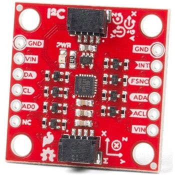 SparkFun 9DoF IMU Breakout - ICM-20948 QwiicSPARKFUN
¥7,298税込¥8,028
1個
33日以内出荷
。Description。The SparkFun 9DoF IMU Breakout incorporates all the amazing features of Invensense's ICM-20948 into a Qwiic-enabled breakout board complete with a logic shifter and broken out GPIO pins for all your motion sensing needs. The ICM-20948 itself is an extremely low powered, I2C and SPI enabled 9-axis motion tracking device that is ideally suited for smartphones, tablets, wearable sensors, and IoT applications. Utilizing our handy Qwiic system, no soldering is required to connect it to the rest of your system. However, we still have broken out 0.1"-spaced pins in case you prefer to use a breadboard.。In addition to the 3-Axis Gyroscope with four selectable ranges, 3-Axis Accelerometer, again with four selectable ranges, and 3-axis magnetometer with an FSR to ±4900μT, the ICM-20948 also includes a Digital Motion Processor that offloads the computation of motion sensing algorithms from the detectors, allowing optimal performance of the sensors. We've also broken out all the ICM-20948 pin functionality to GPIO and labeled them I2C on the front, SPI on the back for ease of identification.。Note:The I2C address of the ICM-20948 is 0x69 and is jumper selectable to 0x68. A multiplexer/Mux is required to communicate to multiple ICM-20948 sensors on a single bus. If you need to use more than one ICM-20948 sensor consider using the Qwiic Mux Breakout.。The SparkFun Qwiic Connect System is an ecosystem of I2C sensors, actuators, shields and cables that make prototyping faster and less prone to error. All Qwiic-enabled boards use a common 1mm pitch, 4-pin JST connector. This reduces the amount of required PCB space, and polarized connections mean you can't hook it up wrong.。Need a custom board? This component can be found in SparkFun's A La Carte board builder. You can have a custom design fabricated with this component - and your choice of hundreds of other sensors, actuators and wireless devices - delivered to you in just a few weeks.。Get Started with the SparkFun ICM-20948 9DoF IMU Guide。Features。1.95 V to 3.6 V supply voltage。Triple-axis MEMS gyroscope with user-programmable full-scale range of ±250 dps, ±500 dps, ±1000 dps, and ±2000 dps。Triple-axis MEMS accelerometer with programmable full scale range of ±2g, ±4g, ±8g, and ±16g。Triple-axis silicon monolithic Hall-effect magnetic sensor with full scale measurement range to ±4900 μT。I2C at up to 100 kHz(standard-mode)or up to 400 kHz(fast-mode)or SPI at up to 7 MHz for communicationwith registers。On-board digital motion processor(DMP)。Digital-output temperature sensor。2x Qwiic Connection Ports。I2C Address:0x69(0x68 with Jumper)。。Documents。Schematic。Eagle Files。Hookup Guide。Datasheet(ICM-20948)。Arduino Library。Python Support(Qwiic_Py)。GitHub Hardware Repo
アズワン品番67-0427-05
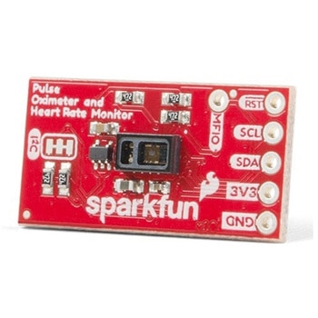 SparkFun Pulse Oximeter and Heart Rate Sensor - MAX30101 & MAX32664 QwiicSPARKFUN
¥13,980税込¥15,378
1個
33日以内出荷
Description。The SparkFun Pulse Oximeter and Heart Rate Sensor is an I2C based biometric sensor, utilizing two chips from Maxim Integrated:the MAX32664 Biometric Sensor Hub and the MAX30101 Pulse Oximetry and Heart Rate Module. While the latter does all the sensing, the former is an incredibly small and fast Cortex M4 processor that handles all of the algorithmic calculations, digital filtering, pressure/position compensation, advanced R-wave detection, and automatic gain control. We've provided a Qwiic connector to easily connect to the I2C data lines but you will also need to connect to two additional lines. This board is very small, measuring at 1in×0.5in(25.4mm×12.7mm), which means it will fit nicely on your finger without all the bulk.。The MAX30101 does all the sensing by utilizing its internal LEDs to bounce light off the arteries and arterioles in your finger's subcutaneous layer and sensing how much light is absorbed with its photodetectors. This is known as photoplethysmography. This data is passed onto and analyzed by the MAX32664 which applies its algorithms to determine heart rate and blood oxygen saturation(SpO2). SpO2 results are reported as the percentage of hemoglobin that is saturated with oxygen. It also provides useful information such as the sensor's confidence in its reporting as well as a handy finger detection data point. To get the most out of the sensor we've written an Arduino Library to make it easy to adjust all the possible configurations.。The SparkFun Qwiic connect system is an ecosystem of I2C sensors, actuators, shields and cables that make prototyping faster and less prone to error. All Qwiic-enabled boards use a common 1mm pitch, 4-pin JST connector. This reduces the amount of required PCB space, and polarized connections mean you can't hook it up wrong.。Get Started with the Pulse Oximeter and Heart Rate Monitor Hookup Guide。Features。SparkFun Pulse Oximeter and Heart Rate Sensor。MAX30101 and MAX32664 sensor and sensor hub。Qwiic connectors for power and I2C interface。I2C Address:0x55。MAX30101 - Pulse Oximeter and Heart-Rate Sensor。Heart-Rate Monitor and Pulse Oximeter Sensor in LED Reflective Solution。Integrated Cover Glass for Optimal, Robust Performance。Ultra-Low Power Operation for Mobile Devices。Fast Data Output Capability。Robust Motion Artifact Resilience。MAX32664 - Ultra-Low Power Biometric Sensor Hub。Biometric Sensor Hub Solution。Finger-Based Algorithms Measure Pulse Heart Rate and Pulse Blood Oxygenation Saturation(SpO2)。Both Raw and processed data are available。Basic Peripheral mix optimizes size and performance
アズワン品番67-0426-96
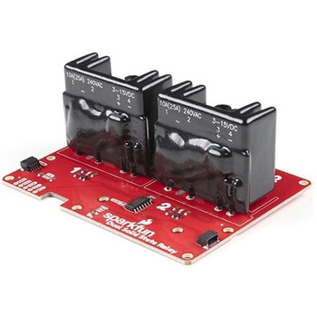 SparkFun Qwiic Dual Solid State RelaySPARKFUN
¥39,980税込¥43,978
1個
33日以内出荷
Description。The SparkFun Qwiic Dual Solid State Relay is a power delivery board that allows users to switch two AC loads from a low power microcontroller using the SparkFun Qwiic connect system. The board features two 25A/250VAC solid state relays that utilize the Zero Cross Trigger method so you can toggle two loads on a 60Hz AC carrier signal on and off up to 120 times per second!。An ATTiny84 acts as the "brain" of the SparkFun Qwiic Dual Solid Relay to accept I2C commands to toggle the two relays as well as a few other special commands. The I2C address of the ATtiny84A is software configurable so, if you have a seriously big power project in mind, you could daisy chain over 100 Qwiic Dual Solid State Relays.。Messing with such high voltage is dangerous! We've included many safety precautions onto the PCB including ground isolation between the relay and other circuitry and a milled out area isolating each side of AC. However, with all the safety precautions included with the SparkFun Qwiic Dual Solid State Relay, this is still a power accessory for users who are experienced around, and knowledgeable about high AC voltage. If you're not comfortable with handling AC voltage in this way, you may want to check out the IoT Power Relay instead.。Note:The relays are rated for a max of 25A with forced air cooling. If you do not have forced air cooling, 10A max through the relays is recommended.。The SparkFun Qwiic connect system is an ecosystem of I2C sensors, actuators, shields and cables that make prototyping faster and less prone to error. All Qwiic-enabled boards use a common 1mm pitch, 4-pin JST connector. This reduces the amount of required PCB space, and polarized connections mean you can't hook it up wrong.。Get Started with the SparkFun Qwiic Dual Solid State Relay Guide。Features。Operating Voltage:2.5-3.6V(3.3V recommended)。I2C Address:0x0A(Default)0x0B(Alternate via jumper select)。Load Voltage Range:12-280VAC。Max Current(Through Relay):25A(240VAC with forced air cooling)。Zero Cross Trigger。Normally Open Circuit Only。2x Qwiic Connector
アズワン品番67-0421-58
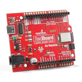 SparkFun RedBoard ArtemisSPARKFUN
¥7,698税込¥8,468
1個
33日以内出荷
。Description。Think of the RedBoard Artemis as just another Arduino... That has BLE. And one megabyte of flash. And runs at less than 1mA. Oh, and it can run TensorFlow models. Ya, that too. The RedBoard Artemis takes the incredibly powerful Artemis module from SparkFun and wraps it up in an easy to use and familiar Uno footprint. We've written an Arduino core from scratch to make programming the Artemis as familiar as。Serial.begin(9600)。. Time-to-first-blink is less than five minutes.。The RedBoard Artemis has the improved power conditioning and USB to serial that we've refined over the years on our RedBoard line of products. A modern USB-C connector makes programming easy. A Qwiic connector makes I2C easy. The RedBoard Artemis is fully compatible with SparkFun's Arduino core and can be programmed easily under the Arduino IDE. We've exposed the JTAG connector for more advanced users who prefer to use the power and speed of professional tools. We've added a digital MEMS microphone for folks wanting to experiment with always-on voice commands with TensorFlow and machine learning. We've even added a convenient jumper to measure current consumption for low power testing.。With 1MB flash and 384k RAM you'll have plenty of room for your sketches. The on-board Artemis module runs at 48MHz with a 96MHz turbo mode available and with Bluetooth to boot!。The SparkFun RedBoard Artemis is a great platform to 'kick the tires' of this amazing module. If you're interesting in testing out the full capabilities of the SparkFun Artemis module or if you're looking for more compact solution, be sure to checkout our ATP and Nano versions of the Artemis line.。Get Started With the SparkFun Artemis RedBoard Guide。Features。Arduino Uno R3 Footprint。1M Flash / 384k RAM。48MHz / 96MHz turbo available。24 GPIO - all interrupt capable。21 PWM channels。Built in BLE radio。10 ADC channels with 14-bit precision。2 UARTs。6 I2C buses。4 SPI buses。PDM Interface。I2S Interface。Qwiic Connector
アズワン品番67-0422-82
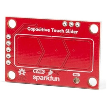 SparkFun Capacitive Touch Slider - CAP1203 QwiicSPARKFUN
¥2,498税込¥2,748
1個
33日以内出荷
。Description。Do you want to replace a slider or a button on your art project or science experiment with a more interesting interface? This Capacitive Touch Slider is a "Qwiic" and easy way to add capacitive touch to your next project. With the board's built in touch pads, you can immediately start playing with the touch capabilities as three unique touch inputs or as a slider. You can also enable a touch input to act as a power button, customize the sensitivity for your own touch pads, and play with the interrupt alert LED. Utilizing our Qwiic system, no soldering is required to connect it to the rest of your system. However, we have broken out 0.1"-spaced pins in case you prefer to use a breadboard or create your own touch pads.。On the front of the board, there is an arrow shape which contains three separate capacitive touch pads. We also broke out the capacitive touch sensor lines as plated through-holes on the top of the board. You can use these pins to connect to your own capacitive touch pads. The CS1 pin connects to the left pad, the CS2 pin connects to the middle pad, and the CS3 pin connects to the right pad.。NOTE:The I2C address of the CAP1203 is 0x28 and is hardware defined. A multiplexer/Mux is required to communicate to multiple CAP1203 sensors on a single bus. If you need to use more than one CAP1203 sensor consider using the Qwiic Mux Breakout.。The SparkFun Qwiic connect system is an ecosystem of I2C sensors, actuators, shields and cables that make prototyping faster and less prone to error. All Qwiic-enabled boards use a common 1mm pitch, 4-pin JST connector. This reduces the amount of required PCB space, and polarized connections mean you can't hook it up wrong.。Get Started with the SparkFun Capacitive Touch Slider Guide。Features。Capacitive Touch。3 unique capacitive touch inputs。Features。Emulated slider。Power button setting。Programmable sensitivity。Automatic recalibration。I2C Address:0x28。Qwiic Enabled。Operating Range。Supply Voltage:3.3V - 5V
アズワン品番67-0427-06
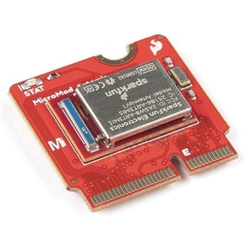 SparkFun MicroMod Artemis ProcessorSPARKFUN
¥6,198税込¥6,818
1個
33日以内出荷
Description。Leveraging the ultra powerful Artemis Module, the SparkFun MicroMod Artemis Processor is the brain board of your dreams. With a Cortex-M4F with BLE 5.0 running up to 96MHz and with as low power as 6uA per MHz(less than 5mW), the M.2 MicroMod connector allows you to plug in a MicroMod Carrier Board with any number of peripherals. Let's have a look at what this processor board has to offer! If you need Machine Learning capabilities, Bluetooth, I2C functionality to connect to all our amazing Qwiic boards, and more the Artemis Processor is the perfect choice for your MicroMod Carrier Board.。At the heart of SparkFun's Artemis Module is Ambiq Micro's Apollo3 processor, whose ultra-efficient ARM Cortex-M4F processor is spec'd to run TensorFlow Lite using only 6uA/MHz. We've routed two I2C buses, eight GPIO, dedicated digital, analog, and PWM pins, multiple SPI as well as QuadSPI, and Bluetooth to boot. You really can't go wrong with this processor. Grab one today, pick up a compatible carrier board, and get hacking!。MicroMod is a modular interface ecosystem that connects a microcontroller "processor board" to various "carrier board" peripherals. Utilizing the M.2 standard, the MicroMod standard is designed to easily swap out processors on the fly. Pair a specialized carrier board for the project you need with your choice of compatible processor!。Get Started with the MicroMod Artemis Processor Guide。Features。Artemis General Features。1M Flash / 384k RAM。48MHz / 96MHz turbo available。6uA/MHz(operates less than 5mW at full operation)。48 GPIO - all interrupt capable。31 PWM channels。Built in BLE radio and antenna。10 ADC channels with 14-bit precision with up to 2.67 million samples per second effective continuous, multi-slot sampling rate。2 channel differential ADC。2 UARTs。6 I2C buses。6 SPI buses。2/4/8-bit SPI bus。PDM interface。I2S Interface。Secure 'Smart Card' interface。FCC/IC/CE Certified(ID Number 2ASW8-ART3MIS)。Specific Peripherals made available on MicroMod Artemis:1x USB dedicated for programming and debug。1x UART with flow control。2x I2C。1x SPI。1x Quad-SPI。8x Fast GPIO。2x Digital Pins。2x Analog Pins。2x PWM。1x Differential ADC pair。Status LED。VIN Level ADC。Additional peripherals are available but are shared on dedicated MicroMod pins.
アズワン品番67-0423-05
 SparkFun 6 Degrees of Freedom Breakout - LSM6DSO QwiicSPARKFUN
¥5,198税込¥5,718
1個
33日以内出荷
Description。The SparkFun LSM6DSO 6 Degrees of Freedom Breakout is an accelerometer and gyroscope sensor with a giant 9kB FIFO buffer and embedded processing interrupt functions. Due to the capabilities and low cost of the LSM6DSO we've created this small breakout board just for you! Each LSM6DSO breakout has been designed to be super-flexible and can be configured specifically for many applications. With the LSM6DSO breakout you will be able to detect shocks, tilt, motion, taps, count steps, and even read the temperature!。The LSM6DSO from STMicroelectronics is capable of reading accelerometer and gyroscope data up to 6.66kHz for more accurate movement sensing. As stated before this breakout also has the ability to buffer up to 9kB of data between reads, host other sensors, and drive interrupt pins all thanks to the LSM6DSO's built-in FIFO.。Utilizing our handy Qwiic system, no soldering is required to connect it to the rest of your system. However, we still have broken out 0.1"-spaced pins in case you prefer to use a breadboard. Each pin has been broken out on the LSM6DSO, with one side of the board featuring power, I2C, and SPI functionality while the other side sporting pins that control auxiliary functionality and interrupt outputs. Please keep in mind that the LSM6DSO is a 3.3V device so supplying voltages greater than ~3.6V can permanently damage the IC. A logic level shifter is required for any development platform operating at 5V.。The SparkFun Qwiic Connect System is an ecosystem of I2C sensors, actuators, shields and cables that make prototyping faster and less prone to error. All Qwiic-enabled boards use a common 1mm pitch, 4-pin JST connector. This reduces the amount of required PCB space, and polarized connections mean you can't hook it up wrong.。Get Started With the SparkFun LSM6DSO Qwiic 6DoF Guide。Features。2x Qwiic connectors。I2C Address。0x6B(default)。, 0x6A。Accelerometer measurement range。±2/±4/±8/±16 g full scale。Gyro measurement range。±125/±250/±500/±1000/±2000 dps full scale。Embedded temperature sensor。16-bit resolution。Operating voltage range。1.71V to 3.6V。Typically。3.3V。if using the Qwiic cable。Power consumption @ 1.8V。0.55 mA in combo high-performance mode。0.265 mA in combo low-power mode。"Always on" experience with low power consumption for both accelerometer and gyroscope。I2C/SPI serial interface with main processor data synchronization feature。Smart FIFO up to 9 kbyte based on features set。Operating temperature range。-40℃ to +85℃
アズワン品番67-0427-54
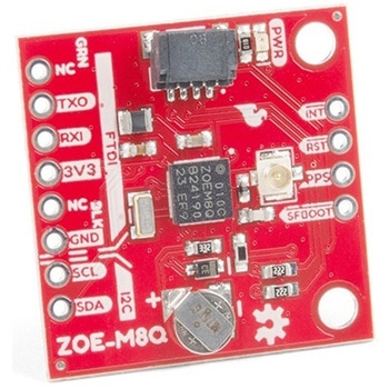 SparkFun GPS Breakout - ZOE-M8Q QwiicSPARKFUN
¥14,980税込¥16,478
1個
33日以内出荷
Description。The SparkFun ZOE-M8Q GPS Breakout is a high accuracy, miniaturized, GPS board that is perfect for applications that don't possess a lot of space. The on-board ZOE-M8Q is a 72-channel GNSS receiver, meaning it can receive signals from the GPS, GLONASS, BeiDou, and Galileo constellations. This increases precision and decreases lock time and thanks to the onboard rechargable battery you'll have backup power enabling the GPS to get a hot lock within seconds! Additionally, this u-blox receiver supports I2C(u-blox calls this Display Data Channel)which made it perfect for the Qwiic compatibility so we don't have to use up our precious UART ports. Utilizing our handy Qwiic system, no soldering is required to connect it to the rest of your system. However, we still have broken out 0.1"-spaced pins in case you prefer to use a breadboard.。U-blox based GPS products are configurable using the popular, but dense, windows program called u-center. Plenty of different functions can be configured on the ZOE-M8Q:baud rates, update rates, geofencing, spoofing detection, external interrupts, SBAS/D-GPS, etc. All of this can be done within the SparkFun Arduino Library. We've also made sure to configure the UART pin grouping on the breakout to an industry standard to insure that it easily connects to a Serial Basic.。The SparkFun ZOE-M8Q GPS Breakout is also equipped with an on-board rechargeable battery that provides power to the RTC on the ZOE-M8Q. This reduces the time-to-first fix from a cold start(~30s)to a hot start(~1s). The battery will maintain RTC and GNSS orbit data without being connected to power for up to five hours. Since the ZOE-M8Q is a tiny GPS receiver and to minimize its footprint, we've added a U.FL connector to allow the use of both large standard ceramic antennas as well as very small chip scale antennas.。Note:The I2C address of the ZOE-M8Q is 0x42 and is software configurable. A multiplexer/Mux is required to communicate to multiple ZOE-M8Q sensors on a single bus. If you need to use more than one ZOE-M8Q sensor consider using the Qwiic Mux Breakout.。The SparkFun Qwiic Connect System is an ecosystem of I2C sensors, actuators, shields and cables that make prototyping faster and less prone to error. All Qwiic-enabled boards use a common 1mm pitch, 4-pin JST connector. This reduces the amount of required PCB space, and polarized connections mean you can't hook it up wrong.。The ZOE-M8Q GPS Breakout can also be automatically detected, scanned, configured, and logged using the OpenLog Artemis datalogger system. No programming, soldering, or setup required!。Get Started With the SparkFun ZOE-M8Q Hookup Guide。Features。72-Channel GNSS Receiver。2.5m Horizontal Accuracy。18Hz Max Update Rate。Time-To-First-Fix:Cold:26s。Hot:1s。Max Altitude:50,000m。Max G:≦4。Max Velocity:500m/s。Velocity Accuracy:0.05m/s。Heading Accuracy:0.3 degrees。Time Pulse Accuracy:30ns。3.3V VCC and I/O。Current Consumption:~29mA Tracking GPS+GLONASS。Software Configurable。Geofencing。Odometer。Spoofing Detection。External Interrupt。Pin Control。Low Power Mode。Many others!。Supports NMEA, UBX, and RTCM protocols over UART or I2C interfaces
アズワン品番67-0423-76
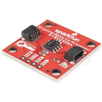 SparkFun Cryptographic Co-Processor Breakout - ATECC608A QwiicSPARKFUN
¥1,498税込¥1,648
1個
33日以内出荷
。Description。Product Restrictions:To access certain features of the ATECC608A, users will need to contact Microchip and sign an NDA contract to obtain the complete datasheet. Due to the required NDA - technical support, an Arduino library, and hookup guide are not provided for users on this product.。The SparkFun ATECC608A Cryptographic Co-processor Breakout allows you to add strong security to your IoT node, edge device, or embedded system. This includes。a。symmetric。authentication,。symmetric。AES-128 encryption/decryption, and much more. As stated above, the ATECC608A has limited Arduino support and the complete datasheet is under NDA with Microchip.。This breakout board includes two Qwiic ports for plug and play functionality. Utilizing our handy Qwiic system, no soldering is required to connect it to the rest of your system. However, we still have broken out 0.1"-spaced pins in case you prefer to use a breadboard. The ATECC608A chip is capable of many cryptographic processes, including, but not limited to:Creating and securely storing unique asymmetric key pairs based on Elliptic Curve Cryptography(FIPS186-3).。AES-128:Encrypt/Decrypt, Galois Field Multiply for GCM。Creating and verifying 64-byte digital signatures(from 32-bytes of message data).。Creating a shared secret key on a public channel via Elliptic Curve Diffie-Hellman Algorithm.。SHA-256 HMAC Hash including off-chip context save/restore。Internal high quality FIPS random number generator.。Embedded in the chip is a 10Kb EEPROM array that can be used for storing keys, certificates, data, consumption logging, and security configurations. Access to the sections of memory can then be restricted and the configuration locked to prevent changes. Each ATECC608A Breakout ships with a guaranteed unique 72-bit serial number and includes several security features to prevent physical attacks on the device itself, or logical attacks on the data transmitted between the device.。A summary datasheet for the ATECC608A is available here. The full datasheet is under NDA with Microchip. You will need to contact them for access to the entire datasheet. Meanwhile, the ArduinoATECCX08 Library currently only supports the ATECC608A with SAMD21 Arduino boards.。We do have much more support for the ATECC508A version of this chip. Please check out our ATECC508A Hookup Guide and Arduino Library(which includes six examples). This will get you familiar with the basics of elliptic curve cryptography and signing/verifying data with the ATECC508A version of the chip.。Note:The I2C address of the ATECC608A is 0x60 and is software-configurable to any address. A multiplexer/Mux is required to communicate to multiple ATECC608A sensors at the default address when on a single bus. If you need to use more than one ATECC608A sensor at the default address, consider using the Qwiic Mux Breakout.。Note:The ATECC608A can be only configured once before it is。PERMANENTLY。locked。. It is advisable that users purchase multiple boards in order to use other configurations and explore the advanced functions of the ATECC608A.。Additionally, this board。IS。capable of encrypting and decrypting data. However, to access these additional features, you will need to contact Microchip and sign an NDA contract to obtain the complete datasheet.。It is recommended that an SparkFun RedBoard Turbo - SAMD21 Development Board is used with this product due to the buffer size required on the I2C bus.。The SparkFun Qwiic Connect System is an ecosystem of I2C sensors, actuators, shields and cables that make prototyping faster and less prone to error. All Qwiic-enabled boards use a common 1mm pitch, 4-pin JST connector. This reduces the amount of required PCB space, and polarized connections mean you can't hook it up wrong.。。Features。Operating Voltage:2.0V-5.5V(。Default on Qwiic System:3.3V。)。Active Current Draw(for ATECC608A):16 mA。Sleep Current(for ATECC608A):<150 nA。Guaranteed Unique 72-bit Serial Number。10 Kb EEPROM Memory for Keys, Certificates, and Data。Storage for up to 16 Keys。256-bit Key Length。Internal High-Quality FIPS Random Number Generator(RNG)。Configurable I2C Address(7-bit):0x60(。Default。)
アズワン品番67-0423-59
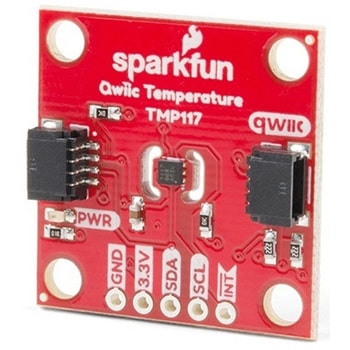 SparkFun High Precision Temperature Sensor - TMP117 QwiicSPARKFUN
¥4,898税込¥5,388
1個
33日以内出荷
。Description。The SparkFun Qwiic TMP117 breakout is a high precision temperature sensor equipped with an I2C interface. It outputs temperature readings with high precision of ±0.1℃ across the temperature range of -20℃ to +50℃s with no calibration and a maximum range from -55℃ to 150℃. The SparkFun High Precision Temperature Sensor also has a very low power consumption rate which minimizes the impact of self-heating on measurement accuracy. Utilizing our handy Qwiic system, no soldering is required to connect it to the rest of your system. However, we still have broken out 0.1"-spaced pins in case you prefer to use a breadboard.。The SparkFun High Precision Temperature Sensor also includes programmable temperature limits, and digital offset for system correction. While the TMP102 is capable of reading temperatures to a resolution of 0.0625℃ and is accurate up to 0.5℃, the on-board TMP117 is not only more precise but has a 16-bit resolution of 0.0078℃!。To make this breakout even easier to use, we've written an Arduino library to help you get started "Qwiic-ly." Check the Documents tab above for more information.。The SparkFun Qwiic Connect System is an ecosystem of I2C sensors, actuators, shields and cables that make prototyping faster and less prone to error. All Qwiic-enabled boards use a common 1mm pitch, 4-pin JST connector. This reduces the amount of required PCB space, and polarized connections mean you can't hook it up wrong.。The TMP117 High Precision Temperature Sensor can also be automatically detected, scanned, configured, and logged using the OpenLog Artemis datalogger system. No programming, soldering, or setup required!。Need a custom board? This component can be found in SparkFun's A La Carte board builder. You can have a custom design fabricated with this component - and your choice of hundreds of other sensors, actuators and wireless devices - delivered to you in just a few weeks.。Get Started with the SparkFun High Precision TMP117 Hookup Guide。Features。Uses I2C interface(Qwiic-enabled)。Four selectable addresses。0x48(default), 0x49, 0x4A, 0x4B。16-bit resolution, 0.0078℃。High accuracy, digital temperature sensor。±0.1℃(max)from ?20℃ to 50℃。±0.15℃(max)from ?40℃ to 70℃。±0.2℃(max)from ?40℃ to 100℃。±0.25℃(max)from ?55℃ to 125℃。±0.3℃(max)from ?55℃ to 150℃。Operating temperature range。-55℃ to +150℃。Operating voltage range。1.8V to 5.5V。Typically 3.3V if using the Qwiic cable。Low power consumption。3.5μA(1-Hz conversion cycle)。150nA(shutdown current)。Programmable operating modes。Continuous, one-shot, and shutdown。Programmable temperature alert limits。Selectable averaging for reduced noise。Digital offset for system correction。NIST traceability。。Documents。Schematic。Eagle Files。Board Dimensions。Hookup Guide。Datasheet(TMP117)。Arduino Library。GitHub Hardware Repo
アズワン品番67-0427-10
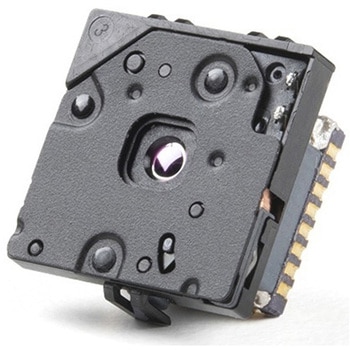 FLIR Lepton 2.5 - Thermal Imaging ModuleSPARKFUN
¥68,980税込¥75,878
1個
33日以内出荷
Description。The FLIR Lepton(R)2.5 - Thermal Imaging Module is a radiometric-capable long wave infrared(LWIR)camera solution that is smaller than a dime, fits inside a smartphone, and is less expensive than traditional IR cameras. With a focal plane array of 80x60 active pixels, this Lepton easily integrates into native mobile-devices and other electronics as an IR sensor or thermal image sensor. The radiometric Lepton captures accurate, calibrated, and non-contact temperature data in every pixel.。For large quantities:We currently have a limit of one per customer order on the FLIR Lepton 2.5 module due to supply chain issues as a result of COVID-19. If you need to place a distributor order please contact your sales rep and they will assist you. For bulk order for this module please visit our Volume Pricing Page for inquiries of stock. At this time, we cannot guarantee orders for this module but we will do what we can to work with you in fulfilling your request.。Features。Effective Frame Rate:8.6 Hz(commercial application exportable)。Input Clock:25-MHz nominal, CMOS IO Voltage Levels。Output Format:User-selectable 14-bit, 8-bit(AGC applied), or 24-bit RGB(AGC and colorization applied)。Pixel Size:17 μm。Radiometric Accuracy:High gain:Greater of +/- 5℃ or 5%(typical)Low gain:Greater of +/- 10℃ or 10%(typical)。Scene Dynamic Range:-10-140 ℃(high gain); up to 450℃(low gain)typical。Spectral Range:Longwave infrared, 8 μm to 14 μm。Temperature Compensation:Automatic. Output image independent of camera temperature.。Thermal Sensitivity:<50 mK(0.050° C)。Video Data Interface:Video over SPI。Control Port:CCI(I2C-like), CMOS IO Voltage Levels。Package Dimensions - Socket Version(w×l×h):11.8×12.7×7.2 mm。Mechanical Interface:32-pin socket interface to standard Molex(R)socket。Non-Operating Temperature Range:-40 ℃ to +80 ℃。Optimum Temperature Range:-10℃ to +80℃。Shock:1500 G @ 0.4 ms。Array format:80×60, progressive scan。FOV - Diagonal:63.5°。FOV - Horizontal:50°(nominal)。Image Optimization:Factory configured and fully automated。Non-Uniformity Correction(NUC):Automatic with shutter。Sensor Technology:Uncooled VOx microbolometer。Solar protection:Integral。Input Supply Voltage:2.8 V, 1.2 V, 2.5 V to 3.1 V IO。Power Dissipation:150 mW(operating), 650 mW(during shutter event), 4 mW(standby)
アズワン品番67-0427-21
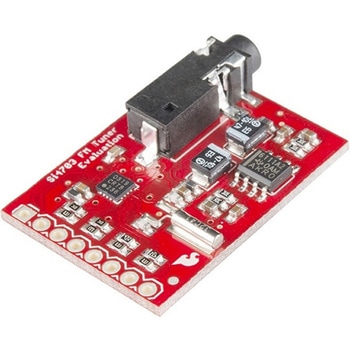 SparkFun FM Tuner Evaluation Board - Si4703SPARKFUN
¥7,298税込¥8,028
1個
33日以内出荷
Description。This is an evaluation board for the Silicon Laboratories Si4703 FM tuner chip. Beyond enabling you to tune in to FM radio stations, the Si4703 is also capable of detecting and processing both Radio Data Service(RDS)and Radio Broadcast Data Service(RBDS)information. The Si4703 even does a very good job of filtering and carrier detection. It also enables data such as the station ID and song name to be displayed to the user.。Using this board, you will be able to pick up multiple stations just as well as with a standard FM radio. The board breaks out all major pins and makes it easy to incorporate this great chip into your next radio project. The power bus, the 3.3V and GND pins are broken out For communication. The breakout provides access to SDIO and SCLK for I2C communication while RST can be used for easy resetting. The SEN pin enables the user to change the mode of functionality of the IC. The last two pins broken out are GPIO1 and GPIO2 which can be used as general input/output pins, but also can be used for things like the RDS ready, seeking or tuning functions.。Keep in mind, by plugging headphones into the 3.5mm audio jack, you effectively use the cable in your headphones as an antenna! Therefore, this board does not require an external antenna if using headphones or a 3.5mm audio cable longer than 3 feet.
アズワン品番67-0429-34
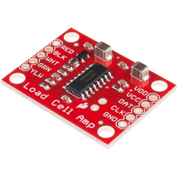 LOAD CELL AMP HX711SPARKFUN
¥3,500税込¥3,850
1個
33日以内出荷
。Description。The SparkFun Load Cell Amplifier is a small breakout board for the HX711 IC that allows you to easily read load cells to measure weight. By connecting the amplifier to your microcontroller you will be able to read the changes in the resistance of the load cell, and with some calibration you'll be able to get very accurate weight measurements. This can be handy for creating your own industrial scale, process control or simple presence detection.。This version of the SparkFun Load Cell Amplifier features a few changes that you specifically asked for! We have separated the analog and digital supply, as well as added a 3.3uH inductor and a 0.1uF filter capacitor for digital supply. Need even more? Checkout the SparkFun Qwiic Scale. It has all the features of the HX711 but with additional library support, a true I2C interface, and no soldering required!。The HX711 uses a two-wire interface(Clock and Data)for communication. Any microcontroller's GPIO pins should work, and numerous libraries have been written, making it easy to read data from the HX711. Check the hookup guide below for more information.。Load cells use a four-wire Wheatstone bridge configuration to connect to the HX711. These are commonly colored RED, BLK, WHT, GRN and YLW. Each color corresponds to the conventional color coding of load cells:Red(Excitation+ or VCC)。Black(Excitation- or GND)。White(Amplifier-, Signal- or Output-)。Green(A+, S+ or O+)。Yellow(Shield)。The YLW pin acts as an optional input that is not hooked up to the strain gauge but is utilized to ground and shield against outside EMI(electromagnetic interference). Please keep in mind that some load cells might have slight variations in color coding.。Note:Special thanks to Bodge for supplying the Library for the HX711!。Get Started with the HX711 Load Cell Amplifier Guide。Features。Operation Voltage:2.7V--5V。Operation Current:< 1.5mA。Selectable 10SPS or 80SPS output data rate。Simultaneous 50 and 60Hz supply rejection
アズワン品番67-0362-17
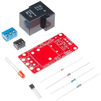 SparkFun Beefcake Relay Control Kit Ver. 2.0SPARKFUN
¥3,198税込¥3,518
1個
33日以内出荷
Description。Your 5V system can wield great power with this big, beefy relay board. How does 10A on the NC contacts and 20A on the NO contacts at 220VAC sound? The SparkFun Beefcake Relay Control Kit contains all the parts you need to get your high-power load under control. Only minimal assembly is required!。The heart of the board is sealed, SPDT 20A/10A Relay. The relay is controlled by 5V logic through transistor, and an LED tells you when the relay is closed. This is kit, so it comes as through-hole parts with assembly required, which makes for some nice soldering practice. Screw terminal connectors on either side of the board make it easy to incorporate into your project.。There are some pretty beefy traces connecting the relay to the load pins, but the 3-pin terminals are only rated for 15A max! If you plan on connecting larger load, you'll need to solder directly to the board. As always with high current and voltage, play it safe and use your judgment when deciding how much of load you want to put on board -- in open airflow the PCB can handle the full 20A for few minutes at time, but in an enclosed area heat can build up.。Note:Please keep in mind that this board is really meant for someone with experience and good knowledge of electricity. If you're uncomfortable soldering or dealing with high voltage, please check out the IoT Power Relay. The IoT Power Relay is fully enclosed, making it lot safer.。Get Started With the Beefcake Hookup Assembly Guide。Features。Voltage Rating:220VAC/28VDC。VCC requirements:4-6V, 150mA capable。SPDT pins exposed(Form C)。14 AWG screw terminals for relay connections.。10 AWG solder lugs for relay connections.。Flyback diode included。Zener recovery diode included(decreases turn-off time)。Heavy oz. copper on PCB
アズワン品番67-0424-03
 SparkFun Thing Plus - XBee3 Micro U.FLSPARKFUN
¥16,980税込¥18,678
1個
33日以内出荷
Description。The XBee3 Thing Plus is an ultra capable and easy way for getting into wireless device development. The combination of XBee and Qwiic in a space conscious design represents a much needed update to our XBee offering. With 20 I/O pins and Lithium Polymer Ion battery management, the XBee3 Thing Plus has all the basics for quickly prototyping or developing a connected device such as a remote sensor. The Qwiic connector and JST connector for the battery make for a solder-less option when working with the board which shortens setup time.。The new XBee3 Micro Module provides the classic all-but plug and play 802.15.4 2.4GHz wireless connection(Zigbee 3.0 Protocol)that makes it so desirable, but with a new addition of being programmable with MicroPython(32KB of memory available for it). RF data rates up to 250 Kbps and 200ft indoor ranges and up to 4000ft line-of-sight outdoor range. Communicating with/Configuring the module happens via an AT Command set or the Digi API, X-CTU, both locally or over-the-air. There's even a mobile version of X-CTU now; Digi XBee(R)Mobile.。This variation features a U.FL antenna connector for longer range communications. Check out the related products for compatible antennas.。Get Started With the SparkFun XBee3 Thing Plus Guide。Features。XBee3 Micro Module。Silicon Labs EFR32MG SoC。250Kbps RF, 1Mbps Serial data rates。Indoor/Urban range up to 200 ft(60 m)。Outdoor/RF Line of Sight range up to 4000 ft(1200 m)。+8 dBm transmit power。-103 dBm receiver sensitivity。UART, I2C, SPI Interfaces(SPI currently not available at this time, but broken out on the board)。ISM 2.4GHz Frequency Band(802.15.4)。1MB of memory, 128KB RAM(32KB available for MicroPython)。20 GPIO Pins。Configurable via X-CTU or AT Command set via both USB and Wirelessly(second XBee 3 device required for wireless configuration unless you're using the mobile app)。Qwiic Compatible。On-board charging circuit and connector for 3.3v Lithium Polymer Ion Batteries(see related products for compatible batteries)。2.6VDC - 3.6VDC supply voltage。U.FL Antenna Connector
アズワン品番67-0429-55
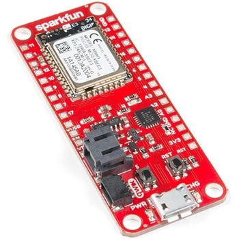 SparkFun Thing Plus - XBee3 Micro Chip AntennaSPARKFUN
¥17,980税込¥19,778
1個
33日以内出荷
Description。The XBee3 Thing Plus is an ultra-capable and easy way for getting into wireless device development. The combination of XBee and Qwiic in a space-conscious design represents a much-needed update to our XBee offering. With 20 I/O pins and Lithium-Polymer Ion battery management, the XBee3 Thing Plus has all the basics for quickly prototyping or developing a connected device such as a remote sensor. The Qwiic connector and JST connector for the battery make for a solder-less option when working with the board which shortens setup time.。The new XBee3 Micro Module provides the classic, near plug and play 802.15.4 2.4GHz wireless connection(Zigbee 3.0 Protocol)that makes it so desirable, but with a new addition of being programmable with MicroPython(32KB of memory available for it). RF data rates up to 250Kbps and 200 ft indoor ranges and up to 4000 ft line-of-sight outdoor range. Communicating with/Configuring the module happens via an AT Command set or the Digi API, X-CTU, both locally or over-the-air. There's even a mobile version of X-CTU now; Digi XBee(R)Mobile.。Note:This variation uses a chip antenna and is not compatible with external antennas.。Get Started With the SparkFun XBee3 Thing Plus Guide。Features。XBee3 Micro Module。Silicon Labs EFR32MG SoC。250Kbps RF, 1Mbps Serial data rates。Indoor/Urban range up to 200 ft(60 m)。Outdoor/RF Line of Sight range up to 4000 ft(1200 m)。+8 dBm transmit power。-103 dBm receiver sensitivity。UART, I2C, SPI Interfaces(SPI currently not available at this time, but broken out on the board)。ISM 2.4GHz Frequency Band(802.15.4)。1MB of memory, 128KB RAM(32KB available for MicroPython)。20 GPIO Pins。Configurable via X-CTU or AT Command set via both USB and Wirelessly(second XBee 3 device required for wireless configuration unless you're using the mobile app)。Qwiic Compatible。On-board charging circuit and connector for 3.3v Lithium Polymer Ion Batteries(see related products for compatible batteries)。2.6VDC - 3.6VDC supply voltage。On-board Chip Antenna
アズワン品番67-0429-57
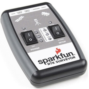 SparkFun RTK SurveyorSPARKFUN
¥129,800税込¥142,780
1個
33日以内出荷
Description。The SparkFun RTK Surveyor is an easy to use GNSS receiver for centimeter-level positioning. Perfect for surveying, this preprogrammed device can also be used for autonomous driving, navigation, asset tracking and any other application where there is a clear view of the sky. The RTK Surveyor can also be used as a base station. With the flick of a switch, two RTK Surveyors can be used to create an RTK system capable of 14mm horizontal positional accuracy. The built-in Bluetooth(R)connection via an ESP32 WROOM enables the user to use the RTK Surveyor with their choice of GIS application on a phone or tablet. The built in battery allows field use for up to four hours and is compatible with common USB battery banks.。This device can be used in four modes:GNSS Positioning(~30cm accuracy)。GNSS Positioning with RTK(1.4cm accuracy)。GNSS Base Station。GNSS Base Station NTRIP Server。In Position mode the device receives L1/L2 signals from a user-provided antenna and the high-grade GNSS receiver provides lat/long and altitude with accuracies around 300mm.。In Positioning with RTK mode the device receives L1/L2 signals from the antenna and correction data from a base station. The correction data can be obtained from a cellular link to online correction sources or over a radio link to a 2nd RTK Surveyor setup as a base station.。In Base Station mode the device is mounted to a temporary position(like a tripod)and begins transmitting correction data over a radio or internet connection. A base is often used in conjunction with a second unit set to 'Positioning with RTK' to obtain the 14mm relative accuracy.。In Base Station NTRIP Server mode the device is mounted to a semi or permanently fixed position(like a roof)and connects over WiFi to transmit the correction data to a NTRIP caster so that any rover can access the correction data over a cellular or internet connection. This type of base is a very easy way to setup a very precise absolute correction source.。Two cables are provided with the RTK Surveyor allowing a user to plug on our easy to use Serial Telemetry Radios or their own radio link. If a local correction source is within 10km, a user can also use their phone to provide correction data over the Bluetooth(R)link(no external radio needed!).。Note:The SparkFun RTK Surveyor is just the enclosed device and does NOT include an antenna, serial telemetry radio, or associated mounting pieces. These items will need to be purchased separately from the Hookup Accessories below.。Get Started With the SparkFun RTK Surveyor Guide。Features。GNSS Receiver:ZED-F9P。Concurrent reception of GPS, GLONASS, Galileo and BeiDou。Receives both L1C/A and L2C bands。Current:68mA - 130mA(varies with constellations and tracking state)。Time to First Fix:25s(cold), 2s(hot)。Max Navigation Rate:PVT(basic location over UBX binary protocol)- 25Hz。RTK - 20Hz。Raw - 25Hz。Horizontal Position Accuracy:2.5m without RTK。0.010m with RTK。Max Altitude:50km(31 miles)。Max Velocity:500m/s(1118mph)。Bluetooth(R)Transceiver:ESP32 WROOM。Xtensa(R)dual-core 32-bit LX6 microprocessor。Up to 240MHz clock frequency。16MB of flash storage。520kB internal SRAM。Integrated 802.11 BGN WiFi transceiver。Integrated dual-mode Bluetooth(R)(classic and BLE)。Hardware accelerated encryption(AES, SHA2, ECC, RSA-4096)。2.5 μA deep sleep current。Overall Device。Internal Battery:LiPo 1000mAh with 500mA charging。Radio Port:3.3V TTL Serial(57600bps RTCM TX/RX)。Data Port:3.3V TTL Serial(115200bps NMEA)。Weight:132g(entire device including battery)。Dimensions:118mm×79mm×30mm(4.7in×3.1in×1.2in)。1x Qwiic Connector。1x microSD Socket for optional logging。Changes:This version(which replaces SPX-17369)uses a reinforced edge mount SMA connector for better resiliency when a fixed 'stub' antenna is used.
アズワン品番67-0423-95