カテゴリ
- 学童・教育用品(17)
- 制御機器(1)
- 空調・照明・電設資材(1)
絞り込み
ブランド
- SPARKFUN
- モノタロウ(1)
- MOTO GRAFIX (モトグラフィックス)(143)
- M5Stack(15)
- RS PRO(9)
- ハネウェル(7)
- Cardo(カルド)(7)
- 三菱ふそう(6)
- Electro Harmonix(4)
- 3M(スリーエム)(3)
- コミネ(3)
- Jabra(3)
- コクヨ(2)
- ミツヤ(2)
- ARCOLECTRIC(2)
- Hirschmann Test & Measurement(2)
- シュナイダーエレクトリック(2)
- Jackery(ジャクリ)(2)
- TORRAS(2)
- エーモン(1)
- ブランドをもっと見る
「blu tack」の検索結果
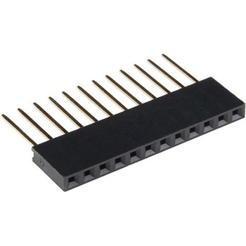
Photon Stackable Header - 12 Pin
SPARKFUN¥289税込¥3181個33日以内出荷Description。These stackable headers are made to work with the Particle Photon and Photon ProtoShield boards. Each header adds a great deal of connectivity to your next Photon project. Each order includes one 1x12 stackable header with pins spaced at 0.1".。If you don't have a Particle Photon, that's fine! These headers will work in any other situation when you need a 12-pin header solution!アズワン品番67-0425-37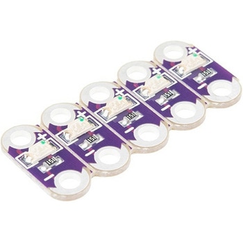
LilyPad LED Blue 5pcs
SPARKFUN¥999税込¥1,0991個33日以内出荷Description。This is a simple pack of five Blue LilyPad LEDs that are still attached to one another, letting you snap the LEDs apart at your leisure to sew into clothing or whatever else you can dream up.。LilyPad is a wearable e-textile technology dアズワン品番67-0422-36エコロジー商品省エネ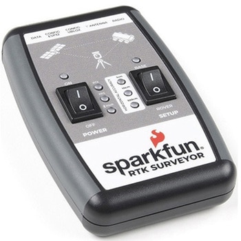
SparkFun RTK Surveyor
SPARKFUN¥129,800税込¥142,7801個33日以内出荷Description。The SparkFun RTK Surveyor is an easy to use GNSS receiver for centimeter-level positioning. Perfect for surveying, this preprogrammed device can also be used for autonomous driving, navigation, asset tracking and any other application where there is a clear view of the sky. The RTK Surveyor can also be used as a base station. With the flick of a switch, two RTK Surveyors can be used to create an RTK system capable of 14mm horizontal positional accuracy. The built-in Bluetooth(R)connection via an ESP32 WROOM enables the user to use the RTK Surveyor with their choice of GIS application on a phone or tablet. The built in battery allows field use for up to four hours and is compatible with common USB battery banks.。This device can be used in four modes:GNSS Positioning(~30cm accuracy)。GNSS Positioning with RTK(1.4cm accuracy)。GNSS Base Station。GNSS Base Station NTRIP Server。In Position mode the device receives L1/L2 signals from a user-provided antenna and the high-grade GNSS receiver provides lat/long and altitude with accuracies around 300mm.。In Positioning with RTK mode the device receives L1/L2 signals from the antenna and correction data from a base station. The correction data can be obtained from a cellular link to online correction sources or over a radio link to a 2nd RTK Surveyor setup as a base station.。In Base Station mode the device is mounted to a temporary position(like a tripod)and begins transmitting correction data over a radio or internet connection. A base is often used in conjunction with a second unit set to 'Positioning with RTK' to obtain the 14mm relative accuracy.。In Base Station NTRIP Server mode the device is mounted to a semi or permanently fixed position(like a roof)and connects over WiFi to transmit the correction data to a NTRIP caster so that any rover can access the correction data over a cellular or internet connection. This type of base is a very easy way to setup a very precise absolute correction source.。Two cables are provided with the RTK Surveyor allowing a user to plug on our easy to use Serial Telemetry Radios or their own radio link. If a local correction source is within 10km, a user can also use their phone to provide correction data over the Bluetooth(R)link(no external radio needed!).。Note:The SparkFun RTK Surveyor is just the enclosed device and does NOT include an antenna, serial telemetry radio, or associated mounting pieces. These items will need to be purchased separately from the Hookup Accessories below.。Get Started With the SparkFun RTK Surveyor Guide。Features。GNSS Receiver:ZED-F9P。Concurrent reception of GPS, GLONASS, Galileo and BeiDou。Receives both L1C/A and L2C bands。Current:68mA - 130mA(varies with constellations and tracking state)。Time to First Fix:25s(cold), 2s(hot)。Max Navigation Rate:PVT(basic location over UBX binary protocol)- 25Hz。RTK - 20Hz。Raw - 25Hz。Horizontal Position Accuracy:2.5m without RTK。0.010m with RTK。Max Altitude:50km(31 miles)。Max Velocity:500m/s(1118mph)。Bluetooth(R)Transceiver:ESP32 WROOM。Xtensa(R)dual-core 32-bit LX6 microprocessor。Up to 240MHz clock frequency。16MB of flash storage。520kB internal SRAM。Integrated 802.11 BGN WiFi transceiver。Integrated dual-mode Bluetooth(R)(classic and BLE)。Hardware accelerated encryption(AES, SHA2, ECC, RSA-4096)。2.5 μA deep sleep current。Overall Device。Internal Battery:LiPo 1000mAh with 500mA charging。Radio Port:3.3V TTL Serial(57600bps RTCM TX/RX)。Data Port:3.3V TTL Serial(115200bps NMEA)。Weight:132g(entire device including battery)。Dimensions:118mm×79mm×30mm(4.7in×3.1in×1.2in)。1x Qwiic Connector。1x microSD Socket for optional logging。Changes:This version(which replaces SPX-17369)uses a reinforced edge mount SMA connector for better resiliency when a fixed 'stub' antenna is used.アズワン品番67-0423-95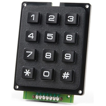
SparkFun Qwiic Keypad - 12 Button
SPARKFUN¥4,198税込¥4,6181個33日以内出荷Description。Keypads are very handy input devices, but who wants to tie up seven GPIO pins, wire up handful of pull-up resistors, and write firmware that wastes valuable processing time scanning the keys for inputs? The SparkFun Qwiic Keypad comes fully assembled and makes the development process for adding 12 button keypad easy. No voltage translation or figuring out which I2C pin is SDA or SCL, just plug and go! Utilizing our handy Qwiic system, no soldering is required to connect it to the rest of your system. However, we still have broken out 0.1"-spaced pins in case you prefer to use breadboard.。Each of the keypad's 12 buttons has been labeled 1, 2, 3, 4, 5, 6, 7, 8, 9, 0, *, and and has been formatted to into the same layout as telephone keypad with each keypress resistance ranging between 10 and 150 Ohms. The Qwiic Keypad reads and stores the last 15 button presses in First-In, First-Out(FIFO)stack, so you don't need to constantly poll the keypad from your microcontroller. This information, then, is accessible through the Qwiic interface. The SparkFun Qwiic Keypad even has software configurable I2C address so you can have multiple I2C devices on the same bus.。NOTE:The I2C address of the Qwiic Keypad is 0x4B and is jumper selectable to 0x4A(software-configurable to any address). multiplexer/Mux is required to communicate to multiple Qwiic Keypad sensors on single bus. If you need to use more than one Qwiic Keypad sensor consider using the Qwiic Mux Breakout.。The SparkFun Qwiic connect system is an ecosystem of I2C sensors, actuators, shields and cables that make prototyping faster and less prone to error. All Qwiic-enabled boards use common 1mm pitch, 4-pin JST connector. This reduces the amount of required PCB space, and polarized connections mean you can't hook it up wrong.。Get Started with the SparkFun Qwiic Keypad Hookup Guide。Features。Software Selectable Slave Address。Low Power ATtiny85 controller。Button Presses w/ Time Stamp。Default I2C Address:0x4B。2x Qwiic Connectorアズワン品番67-0421-41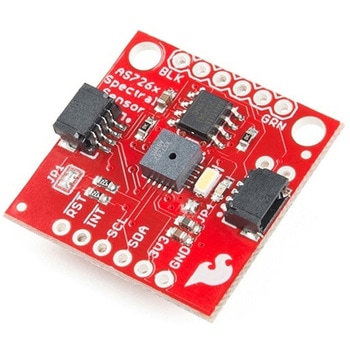
SparkFun Spectral Sensor Breakout - AS7263 NIR Qwiic
SPARKFUN¥9,998税込¥10,9981個33日以内出荷Description。The SparkFun AS7263 Near Infrared(NIR)Spectral Sensor Breakout brings spectroscopy to the palm of your hand, making it easier than ever to measure and characterize how different materials absorb and reflect different wavelengths of light. The AS7263 Breakout is unique in its ability to communicate by both an I2C interface and serial interface using AT commands. Hookup is easy, thanks to the Qwiic connectors attached to the board --- simply plug one end of the Qwiic cable into the breakout and the other into one of the Qwiic shields, then stack the board on a development board. You'll be ready to upload a sketch to start taking spectroscopy measurements in no time.。The AS7263 spectrometer detects wavelengths in the visible range at 610, 680, 730, 760, 810 and 860nm of light, each with 20nm of full-width half-max detection. The board also has multiple ways for you to illuminate objects that you will try to measure for a more accurate spectroscopy reading. There is an onboard LED that has been picked out specifically for this task, as well as two pins to solder your own LED into.。Note:The I2C address of the AS7263 is 0x49 and is hardware defined. A multiplexer/Mux is required to communicate to multiple AS7263 sensors on a single bus. If you need to use more than one AS7263 sensor consider using the Qwiic Mux Breakout.。The SparkFun Qwiic Connect System is an ecosystem of I2C sensors, actuators, shields and cables that make prototyping faster and less prone to error. All Qwiic-enabled boards use a common 1mm pitch, 4-pin JST connector. This reduces the amount of required PCB space, and polarized connections mean you can't hook it up wrong.。Get Started with the SparkFun AS726X Spectral Sensor Breakout Guide。Features。6 near-IR channels:610nm, 680nm, 730nm, 760nm, 810nm and 860nm, each with 20nm FWHM。NIR filter set realized by silicon interference filters。16-bit ADC with digital access。Programmable LED drivers。2.7V to 3.6V with I2C interface。2x Qwiic connectorsアズワン品番67-0426-70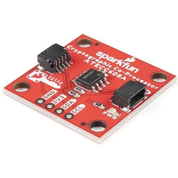
SparkFun Cryptographic Co-Processor Breakout - ATECC608A Qwiic
SPARKFUN¥1,498税込¥1,6481個33日以内出荷。Description。Product Restrictions:To access certain features of the ATECC608A, users will need to contact Microchip and sign an NDA contract to obtain the complete datasheet. Due to the required NDA - technical support, an Arduino library, and hookup guide are not provided for users on this product.。The SparkFun ATECC608A Cryptographic Co-processor Breakout allows you to add strong security to your IoT node, edge device, or embedded system. This includes。a。symmetric。authentication,。symmetric。AES-128 encryption/decryption, and much more. As stated above, the ATECC608A has limited Arduino support and the complete datasheet is under NDA with Microchip.。This breakout board includes two Qwiic ports for plug and play functionality. Utilizing our handy Qwiic system, no soldering is required to connect it to the rest of your system. However, we still have broken out 0.1"-spaced pins in case you prefer to use a breadboard. The ATECC608A chip is capable of many cryptographic processes, including, but not limited to:Creating and securely storing unique asymmetric key pairs based on Elliptic Curve Cryptography(FIPS186-3).。AES-128:Encrypt/Decrypt, Galois Field Multiply for GCM。Creating and verifying 64-byte digital signatures(from 32-bytes of message data).。Creating a shared secret key on a public channel via Elliptic Curve Diffie-Hellman Algorithm.。SHA-256 HMAC Hash including off-chip context save/restore。Internal high quality FIPS random number generator.。Embedded in the chip is a 10Kb EEPROM array that can be used for storing keys, certificates, data, consumption logging, and security configurations. Access to the sections of memory can then be restricted and the configuration locked to prevent changes. Each ATECC608A Breakout ships with a guaranteed unique 72-bit serial number and includes several security features to prevent physical attacks on the device itself, or logical attacks on the data transmitted between the device.。A summary datasheet for the ATECC608A is available here. The full datasheet is under NDA with Microchip. You will need to contact them for access to the entire datasheet. Meanwhile, the ArduinoATECCX08 Library currently only supports the ATECC608A with SAMD21 Arduino boards.。We do have much more support for the ATECC508A version of this chip. Please check out our ATECC508A Hookup Guide and Arduino Library(which includes six examples). This will get you familiar with the basics of elliptic curve cryptography and signing/verifying data with the ATECC508A version of the chip.。Note:The I2C address of the ATECC608A is 0x60 and is software-configurable to any address. A multiplexer/Mux is required to communicate to multiple ATECC608A sensors at the default address when on a single bus. If you need to use more than one ATECC608A sensor at the default address, consider using the Qwiic Mux Breakout.。Note:The ATECC608A can be only configured once before it is。PERMANENTLY。locked。. It is advisable that users purchase multiple boards in order to use other configurations and explore the advanced functions of the ATECC608A.。Additionally, this board。IS。capable of encrypting and decrypting data. However, to access these additional features, you will need to contact Microchip and sign an NDA contract to obtain the complete datasheet.。It is recommended that an SparkFun RedBoard Turbo - SAMD21 Development Board is used with this product due to the buffer size required on the I2C bus.。The SparkFun Qwiic Connect System is an ecosystem of I2C sensors, actuators, shields and cables that make prototyping faster and less prone to error. All Qwiic-enabled boards use a common 1mm pitch, 4-pin JST connector. This reduces the amount of required PCB space, and polarized connections mean you can't hook it up wrong.。。Features。Operating Voltage:2.0V-5.5V(。Default on Qwiic System:3.3V。)。Active Current Draw(for ATECC608A):16 mA。Sleep Current(for ATECC608A):<150 nA。Guaranteed Unique 72-bit Serial Number。10 Kb EEPROM Memory for Keys, Certificates, and Data。Storage for up to 16 Keys。256-bit Key Length。Internal High-Quality FIPS Random Number Generator(RNG)。Configurable I2C Address(7-bit):0x60(。Default。)アズワン品番67-0423-59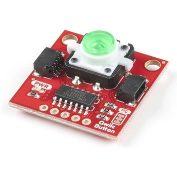
SparkFun Qwiic Button - Green LED
SPARKFUN¥1,698税込¥1,8681個33日以内出荷Description。Buttons are an easy and tactile way to interface with your project, but why would you want to deal with debouncing, polling, and wiring up pull-up resistors? The Qwiic Button with built-in green LED simplifies all of those nasty worries away into an easy to use I2C device! Utilizing our Qwiic Connect System, using the button is as simple as connecting cable and loading up some pre-written code!。If you need multiple buttons for your project, fear not! Each button has configurable I2C address, so you can daisy-chain multiple buttons over Qwiic and still address each one individually. We've got an example in our Arduino library that provides super-easy way to configure your Qwiic Button to whatever I2C address you desire. You can download the library through the Arduino library manager by searching 'SparkFun Qwiic Button' or you can get the GitHub repo as .zip file and install the library from there.。In addition to handling blinking and debouncing, the Qwiic Button has configurable interrupts that can be configured to activate upon button press or click. We've also taken the liberty of implementing FIFO queue onboard the Qwiic Button where it keeps an internal record of when the button was pressed. This means that code on your microcontroller need not waste valuable processing time checking the status of the button but instead can run small function whenever the button is pressed or clicked! For more information on interrupts check out our guide here!。The SparkFun Qwiic Connect System is an ecosystem of I2C sensors, actuators, shields and cables that make prototyping faster and less prone to error. All Qwiic-enabled boards use common 1mm pitch, 4-pin JST connector. This reduces the amount of required PCB space, and polarized connections mean you can't hook it up wrong.。Get Started with the SparkFun Qwiic Button Guide。Features。12mm Green LED Button rated for 50mA。Built in LED can be configured for your desired level of blinkiness!。Each button has configurable I2C address。Configurable interrupts check out our guide here!。FIFO queue。Don't like the color green? Check out the SparkFun Qwiic Button Breakout and add another colored button!。Red LED Tactile Button。Blue LED Tactile Button。Green LED Tactile Button。White LED Tactile Buttonアズワン品番67-0420-14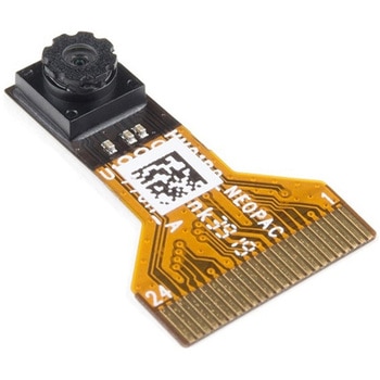
Himax CMOS Imaging Camera - HM01B0
SPARKFUN¥3,698税込¥4,0681個33日以内出荷。Description。The HM01B0 from Himax Imaging is an ultra low power CMOS Monochrome Image Sensor that enables the integration of an "Always On" camera for computer vision applications such as gestures, intelligent ambient light and proximity sensing, tracking and object identification. The sensor allows the sensor to consume very low power of <2mW at QVGA 30FPS. This low power consumption and vision applications camera comes with a ribbon cable that mates to the camera connector populated on the following products:MicroMod Machine Learning Carrier Board。Artemis Development Kit。Edge Development Board - Apollo3 Blue。The HM01B0 contains 320×320 pixel resolution and supports a 320×240 window mode which can be readout at a maximum frame rate of 60FPS, and a 2×2 monochrome binning mode with a maximum frame rate of 120FPS. The video data is transferred over a configurable 1bit, 4bit or 8bit interface with support for frame and line synchronization. The sensor integrates black level calibration circuit, automatic exposure and gain control loop, self-oscillator and motion detection circuit with interrupt output to reduce host computation and commands to the sensor to optimize the system power consumption.。Features。Image Sensor。Ultra Low Power Image Sensor(ULPIS)designed for Always On vision devices and applications。High sensitivity 3.6μ BrightSenseTM pixel technology。320×320 active pixel resolution with support for QVGA window, vertical flip and horizontal mirror readout。Programmable black level calibration target, frame size, frame rate, exposure, analog gain(up to 8x)and digital gain(up to 4x)。Automatic exposure and gain control loop with support for 50 / 60Hz flicker avoidance。Flexible 1bit, 4bit and 8bit video data interface with video frame and line sync。Motion Detection circuit with programmable ROI and detection threshold with digital output to serve as an interrupt。On-chip self oscillator。I2C 2-wire serial interface for register access。High CRA for low profile module design。Sensor Parameters。Active Pixel Array 320×320。Pixel Size 3.6 μm×3.6 μm。Full Image Area 1152 μm×1152 μm。Diagonal(Optical Format)1.63 mm(1/11″)。Scan Mode:Progressive。Shutter Type:Electronic Rolling Shutter。Frame Rate MAX 51 fps @ 320×320, 60 fps @ 320×240(QVGA)。CRA(maximum)30℃。Sensor Specifications。Supply Voltage:Analog - 2.8 V, Digital - 1.5V(Internal LDO:1.5V - 2.8V), I/O - 1.5 - 2.8V。Input Reference Clock:3 - 50 MHz。Serial Interface(I2C):2-wire, 400 KHz max.。Video Data Interface:1b, 4b, 8b with frame / line SYNC。Output Clock Rate MAX:50 MHz for 1bit, 12.5 MHz for 4bit, 6.25 MHz for 8bit。Est. Power Consumption(include IO with 5pF load):QVGA 60FPS(Typical)<4 mW。QVGA 30FPS(Typical)<2 mWアズワン品番67-0427-08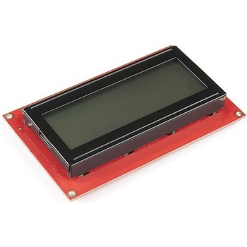
SparkFun 20x4 SerLCD - RGB Backlight Qwiic
SPARKFUN¥13,980税込¥15,3781個33日以内出荷Description。The SparkFun SerLCD is an AVR-based, serial enabled LCD that provides a simple and cost effective solution for adding a 20x4 Black on RGB Liquid Crystal Display into your project. We've seriously overhauled the PCB design on the back of thアズワン品番67-0425-02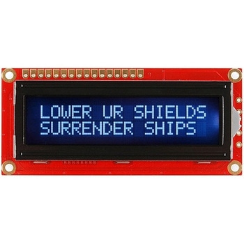
SparkFun Basic 16x2 Character LCD - White on Black, 5V with Headers
SPARKFUN¥7,198税込¥7,9181個33日以内出荷Description。This is a basic 16 character by two line display with a snazzy black background with white characters. This LCD utilizes the extremely common HD44780 parallel interface chipset. Interface code is freely available. This is the same LCD that is included with the SparkFun Inventor's Kit and comes with all the GPIO pins pre-soldered on for quick and easy interfacing.。Includes white LED backlight.。Get Started with the Basic Character LCD Guide。Features。3.15"×1.425"アズワン品番67-0425-06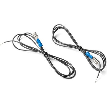
Spade Connector Wire - 3ft, Female 2 Pack
SPARKFUN¥719税込¥7911個33日以内出荷。Description。These simple 24AWG wires are terminated with a female insulated spade connector at one end and a braided wire lead at the other. Each wire is 3 feet long and is capable of supporting a high voltage of 300VDC. Each order comes in a pack of two!。We use these cables almost exclusively on our Spectacle Button Board, but that doesn't mean you can't find a different use for them!。Documentation:。Dimensional Drawing。。Features。3ft(0.9m)lengthアズワン品番67-0420-31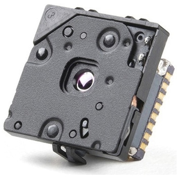
FLIR Lepton 2.5 - Thermal Imaging Module
SPARKFUN¥68,980税込¥75,8781個33日以内出荷Description。The FLIR Lepton(R)2.5 - Thermal Imaging Module is a radiometric-capable long wave infrared(LWIR)camera solution that is smaller than a dime, fits inside a smartphone, and is less expensive than traditional IR cameras. With a focal plane array of 80x60 active pixels, this Lepton easily integrates into native mobile-devices and other electronics as an IR sensor or thermal image sensor. The radiometric Lepton captures accurate, calibrated, and non-contact temperature data in every pixel.。For large quantities:We currently have a limit of one per customer order on the FLIR Lepton 2.5 module due to supply chain issues as a result of COVID-19. If you need to place a distributor order please contact your sales rep and they will assist you. For bulk order for this module please visit our Volume Pricing Page for inquiries of stock. At this time, we cannot guarantee orders for this module but we will do what we can to work with you in fulfilling your request.。Features。Effective Frame Rate:8.6 Hz(commercial application exportable)。Input Clock:25-MHz nominal, CMOS IO Voltage Levels。Output Format:User-selectable 14-bit, 8-bit(AGC applied), or 24-bit RGB(AGC and colorization applied)。Pixel Size:17 μm。Radiometric Accuracy:High gain:Greater of +/- 5℃ or 5%(typical)Low gain:Greater of +/- 10℃ or 10%(typical)。Scene Dynamic Range:-10-140 ℃(high gain); up to 450℃(low gain)typical。Spectral Range:Longwave infrared, 8 μm to 14 μm。Temperature Compensation:Automatic. Output image independent of camera temperature.。Thermal Sensitivity:<50 mK(0.050° C)。Video Data Interface:Video over SPI。Control Port:CCI(I2C-like), CMOS IO Voltage Levels。Package Dimensions - Socket Version(w×l×h):11.8×12.7×7.2 mm。Mechanical Interface:32-pin socket interface to standard Molex(R)socket。Non-Operating Temperature Range:-40 ℃ to +80 ℃。Optimum Temperature Range:-10℃ to +80℃。Shock:1500 G @ 0.4 ms。Array format:80×60, progressive scan。FOV - Diagonal:63.5°。FOV - Horizontal:50°(nominal)。Image Optimization:Factory configured and fully automated。Non-Uniformity Correction(NUC):Automatic with shutter。Sensor Technology:Uncooled VOx microbolometer。Solar protection:Integral。Input Supply Voltage:2.8 V, 1.2 V, 2.5 V to 3.1 V IO。Power Dissipation:150 mW(operating), 650 mW(during shutter event), 4 mW(standby)アズワン品番67-0427-21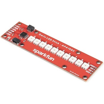
SparkFun Qwiic LED Stick - APA102C
SPARKFUN¥3,500税込¥3,8501個33日以内出荷Description。The SparkFun Qwiic LED Stick features ten addressable APA102 LEDs, making it easy to add full color LED control using I2C. Write to individual LEDs to display a count in binary, or write to the whole strip for cool lighting effects. You can even add more LEDs to the end if you need to. We've written an Arduino library and Python package that take care of the I2C and communication to the LEDs so all you have to do is decide what color each LED should be.。The LED Stick has a default I2C address of 0x23 but can be changed with a simple command, allowing you to control up to 100 LEDs(10 Qwiic LED Sticks)on a single bus! The address can also be changed to 0x22 by closing the solder jumper on the back of the board.。This board is one of our many Qwiic compatible boards! Simply plug and go. No soldering, no figuring out which is SDA or SCL, and no voltage regulation or translation required!。Warning:Using a lot of LEDs can draw a lot of current. Make sure to consider the power limits of your setup. If you expect your LED chain to draw more than 600mA of current, connect your external supply directly to VLED. Closing the jumper from VLED to VCC will add a 4.7uF decoupling capacitor.。The SparkFun Qwiic Connect System is an ecosystem of I2C sensors, actuators, shields and cables that make prototyping faster and less prone to error. All Qwiic-enabled boards use a common 1mm pitch, 4-pin JST connector. This reduces the amount of required PCB space, and polarized connections mean you can't hook it up wrong.。Get Started with the Qwiic LED Stick Guide。Features。10x APA102C addressable LEDs driven by an ATTiny85。Default I2C Address:0x23(Adjustable to 0x22 via Jumper)。2x Qwiic Connectorsアズワン品番67-0421-83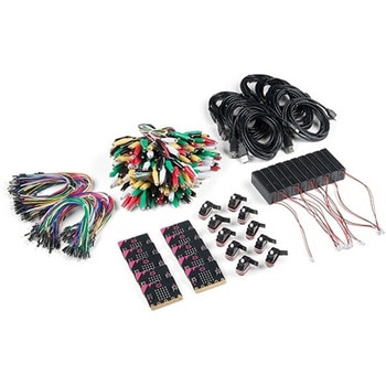
SparkFun Educator Lab Pack for micro:bit v2
SPARKFUN¥109,800税込¥120,7801個33日以内出荷Description。The micro:bit v2 Educator's Lab Pack includes 10 micro:bit v2 boards and everything you need to get you started with the new learning platform. The Lab Pack has everything you need, including micro:bits, cables, battery packs and a few parts to experiment with. This package provides an easy way to introduce your students to the micro:bit without any difficulty or parts hunting.。SparkFun packages everything educators need to get started with the micro:bit in a variety of classroom settings and learning environments. The hardware boards, cables and extra parts come pre-packaged. Examples and curriculum materials are available from SparkFun and micro:bit, as well as from other educators involved in this growing maker education movement.。Lab Packs are your classroom entry point. By combining our kits, popular boards and other educational tools with support materials(to be updated), SparkFun brings all the power of the open source community to the classroom. We've also updated the battery pack to be closer to what is in other micro:bit kits. It now requires 2xAAA batteries.。The micro:bit is a pocket-sized computer that lets you get creative with digital technology. Between the micro:bit and our shield-like bit boards you can do almost anything while coding, customizing and controlling your micro:bit from almost anywhere! You can use your micro:bit for all sorts of unique creations, from robots to musical instruments and more. At half the size of a credit card, this versatile board has vast potential!。。Features。Micro:bit 2.0:64 MHz Arm Cortex-M4 with FPU。512KB Flash。128KB RAM。5x5 Red LED Array。Two Programmable Buttons, one touch sensitive logo。MEMS microphone and LED indicator。Onboard Light, Compass, Accelerometer, Temp Sensors and Speaker。2.4 Ghz Micro:bit Radio/BLE 5.0 Smart Antenna。25-pin Edge Connector。4 dedicated GPIO, PWM, i2c, SPI, and ext. power。Three Digital/Analog Input/Output Rings。Two Power Rings --- 3V and GND。Dedcated I2C bus for peripherals。MicroUSB Connector(5V)。JST-PH Battery Connector(。Not。JST-XH)(3V)。Power/reset Button with Status LED。200 mA available for accessories。Program with C++, MakeCode, Python, Scratchアズワン品番67-0424-92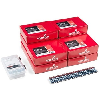
SparkFun Inventor's Kit for micro:bit v2 Lab Pack
SPARKFUN¥159,800税込¥175,7801個33日以内出荷Description。The SparkFun Inventor's Kit for micro:bit v2 Lab Pack includes 10 complete micro:bit v2 Inventor's Kits, an SIK Refill Pack and 25 AAA-sized batteries to get your students started in the world of electronics. The SIKs inside the Lab Pack have everything you need, including micro:bit v2s, connector breakouts, breadboards and all the cables and accessories to hook up all the projects listed in our online Experiment Guide.。The kit does not require any soldering and is recommended for all users, from beginners to engineering students. We have provided a complete Experiment Guide in the Documents tab for you to check out now! If you are new to teaching electronics or have taught with the original SparkFun Inventor's Kit and are looking for something new, the SIK for micro:bit v2 is the perfect kit for you!。SparkFun packages everything educators need to get started with this platform in a variety of classroom and makerspace settings with diverse student populations. The hardware boards, cables and extra parts come pre-packaged, and our online support materials --- including an online Experiment Guide(to be updated)--- help you bring the power of the open source community to your classroom. Examples and curriculum materials are available from SparkFun and Arduino, as well as from other educators involved in this growing maker movement.。The micro:bit is a pocket-sized computer that lets you get creative with digital technology. Between the micro:bit and our shield-like bit boards you can do almost anything while coding, customizing and controlling your micro:bit from almost anywhere! You can use your micro:bit for all sorts of unique creations, from robots to musical instruments and more. At half the size of a credit card, this versatile board has vast potential!アズワン品番67-0424-93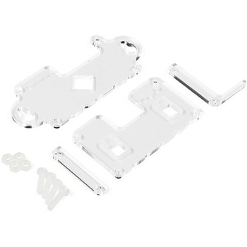
MI:pro Mountable Case for micro:bit V2
SPARKFUN¥1,998税込¥2,1981個33日以内出荷Description。The Mountable MI:pro is a simple and compact protective case for the micro:bit. This case has been specifically designed with portability and expansion in mind and is compatible with both the original micro:bit V1 and the micro:bit V2. These cases feature a three-layer construction style with ability to wall-mount the whole assembly onto any surface you want while still providing access to all buttons and ports on the micro:bit. Though these cases do feature wall-mountable tabs, the biggest benefit of using a case is to not accidentally short out the pads on the back of the micro:bit.。Construction is simple, requiring only a small flathead screwdriver, and involves layering each plate on top of one another around the micro:bit and screwing it into place. Luckily, the MI:pro case enables easy access to the edge pins at the bottom of the micro:bit, allowing it to still be plugged into an edge connector found on many of our carrier boards. The only board that cannot be used in conjunction with the MI:pro case is the SparkFun gamer:bit due to its edge connector being located in the center of the board.。Note:The MI:pro case only includes the parts found in the Includes Tab. This case does NOT include a micro:bit, power source or mounting screws. These items will need to be purchased separately.。Features。Dimensions:Length(minus the mounting brackets on the side):65mm.。Length(with the mounting brackets on the side):91mm.。Width:37mm.。Depth(without screws):9mm.。Depth(with screws):14mm.。Provides excellent protection to the BBC micro:bit whilst allowing access to the bottom pins.。Full access to the A and B buttons on the BBC micro:bit.。The mounting points allow you to fix the micro:bit to a surface for sturdy and more permanent installations.。Full access to pins and connections including the micro USB connector.。Clear case material shows the on-board LEDs in perfect clarity.。The case is compatible with versions 1 and 2 of the micro:bit.アズワン品番67-0426-14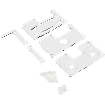
MI:pro Protector Case for micro:bit V2
SPARKFUN¥2,398税込¥2,6381個33日以内出荷Description。This MI:pro Protector Case for the BBC micro:bit has been designed to work with both the original micro:bit V1 and the micro:bit V2. These cases feature a four-layer construction style with ability to mount a 2xAAA battery pack to the back of the case while still providing access to all buttons and ports on the micro:bit. Though these cases do protect the micro:bit astoundingly well, the biggest benefit of using the MI:pro is to not accidentally short out the pads on the back of the micro:bit.。Construction is simple, requiring only a small flathead screwdriver(at most), and involves layering each plate on top of one another around the micro:bit and screwing it into place. Luckily, the MI:pro Protector case enables easy access to the edge pins at the bottom of the micro:bit, allowing it to still be plugged into an edge connector found on many of our carrier boards. The only board that cannot be used in conjunction with the MI:pro case is the SparkFun gamer:bit due to its edge connector being located in the center of the board.。Note:The MI:pro Protector case only includes the parts found in the Includes Tab. This case does。NOT。include a micro:bit, power source or mounting screws. These items will need to be purchased separately.。Features。Dimensions:Length:65mm.。Width:37mm.。Depth(without screws):12mm.。Depth(with screws):18.5mm.。Provides excellent protection to the BBC micro:bit whilst allowing access to the bottom pins.。Full access to the A and B buttons on the BBC micro:bit.。Attach a battery cage to the rear of the case with the supplied sticky fixer.。Full access to pins and connections including the micro USB connector.。Clear case material shows the on-board LEDs in perfect clarity.。The case is compatible with versions 1 and 2 of the micro:bit.。When used in conjunction with a battery holder, micro:bit projects can be fully mobile.アズワン品番67-0426-13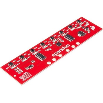
SparkFun Line Follower Array
SPARKFUN¥13,980税込¥15,3781個33日以内出荷Description。The SparkFun Line Follower Array is a long board consisting of eight IR sensors that have been configured to read as digital bits! We have designed the SparkFun Line Follower Arrays to follow a dark line of about 3/4 inch width or smaller(spray paint or electrical tape)on a light background. Each array features visible LEDs that point upward when the board is attached(properly)so you can see what the robot sees, brightness control right on the board, and an I2C interface for reading and power control. Here at SparkFun, the RedBot Shadow Chassis was used as a test platform but really this was designed as an add-on for almost any bot.。The line follower functions by taking an 8-bit reading of reflectance for use with following lines or reading dark/light patterns and can see from about 1/4 to 3/4 inches away. The IR brightness control and indicator can be adjusted with the on-board potentiometer and is capable of showing you the strength of the IR LEDs. Illumination can be turned on and off with software to conserve power, or left on all the time for faster readings. The SparkFun Line Follower Array requires 5V of power with a supply current range of 25-185mA with strobing disabled and 16-160mA with it enabled. Additionally we have added six mounting holes to the line follower with the two inner holes designed to fit our Shadow Chassis while the other four are general purpose.。Note:As you know our Sun emits quite a bit of infrared light, making the SparkFun Line Follower Array much less effective in direct sunlight. Plan your projects accordingly!。Features。8 sensor eyes(QRE1113, like in our line sensor breakout)。I2C interface。Adjust IR brightness on the fly with a knob。Switch IR on and off with software。Switch visual indicators on and off with software。Invert dark/light sight with software。Based on the SX1509 I/O expanderアズワン品番67-0426-55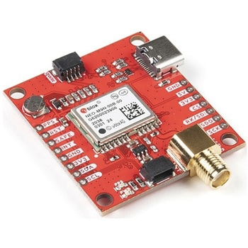
SparkFun GPS Breakout - NEO-M9N, SMA Qwiic
SPARKFUN¥22,980税込¥25,2781個33日以内出荷Description。The SparkFun NEO-M9N GPS Breakout is a high quality GPS board with equally impressive configuration options including SMA. The NEO-M9N module is a 92-channel u-blox M9 engine GNSS receiver, meaning it can receive signals from the GPS, GLONASS, Galileo, and BeiDou constellations with ~1.5 meter accuracy. This breakout supports concurrent reception of four GNSS. This maximizes position accuracy in challenging conditions increasing, precision and decreases lock time; and thanks to the onboard rechargeable battery, you'll have backup power enabling the GPS to get a hot lock within seconds! Additionally, this u-blox receiver supports I2C(u-blox calls this Display Data Channel)which makes it perfect for the Qwiic compatibility so we don't have to use up our precious UART ports. Utilizing our handy Qwiic system, no soldering is required to connect it to the rest of your system. However, we still have broken out 0.1"-spaced pins in case you prefer to use a breadboard.。The NEO-M9N module detects jamming and spoofing events and can report them to the host, so that the system can react to such events. A SAW(Surface Acoustic Wave)filter combined with an LNA(Low Noise Amplifier)in the RF path is integrated into the NEO-M9N module which allows normal operation even under strong RF interferences.。U-blox based GPS products are configurable using the popular, but dense, windows program called u-center. Plenty of different functions can be configured on the NEO-M9N:baud rates, update rates, geofencing, spoofing detection, external interrupts, SBAS/D-GPS, etc. All of this can be done within the SparkFun Arduino Library!。The SparkFun NEO-M9N GPS Breakout is also equipped with an on-board rechargeable battery that provides power to the RTC on the NEO-M9N. This reduces the time-to-first fix from a cold start(~24s)to a hot start(~2s). The battery will maintain RTC and GNSS orbit data without being connected to power for plenty of time.。This product requires an antenna:Be sure to check out the related products/hookup accessories and pick a suitable SMA antenna for your project.。The SparkFun Qwiic Connect System is an ecosystem of I2C sensors, actuators, shields and cables that make prototyping faster and less prone to error. All Qwiic-enabled boards use a common 1mm pitch, 4-pin JST connector. This reduces the amount of required PCB space, and polarized connections mean you can't hook it up wrong.。The NEO-M9N GPS Breakout can also be automatically detected, scanned, configured, and logged using the OpenLog Artemis datalogger system. No programming, soldering, or setup required!。Get Started With the SparkFun NEO-M9N GPS Guide。Features。Integrated SMA connector for use with antenna of your choice。92-Channel GNSS Receiver。1.5m Horizontal Accuracy。25Hz Max Update Rate(four concurrent GNSS)。Time-To-First-Fix:Cold:24s。Hot:2s。Max Altitude:80,000m。Max G:≦4。Max Velocity:500m/s。Velocity Accuracy:0.05m/s。Heading Accuracy:0.3 degrees。Time Pulse Accuracy:30ns。3.3V VCC and I/O。Current Consumption:~31mA Tracking GPS+GLONASS。Software Configurable。Geofencing。Odometer。Spoofing Detection。External Interrupt。Pin Control。Low Power Mode。Many others!。Supports NMEA, UBX, and RTCM protocols over UART or I2C interfacesアズワン品番67-0423-87