カテゴリ
- 学童・教育用品(5)
- 制御機器(1)
絞り込み
ブランド
- SPARKFUN
- 三菱ふそう(29)
- 萩原(11)
- 日本法令(9)
- S.Yairi(9)
- ホンダ(8)
- 興研(4)
- PICOTEST(ピコテスト)(4)
- HIOKI(日置電機)(3)
- トヨタ(3)
- MOTO GRAFIX (モトグラフィックス)(3)
- NBK(鍋屋バイテック会社)(2)
- イチネンTASCO(2)
- RS PRO(2)
- SMC(1)
- 共立電気計器(1)
- MAZDA(マツダ)(1)
- ラムマウント(1)
- RIGOL(リゴル)(1)
- ブランドをもっと見る
「brdg」の検索結果
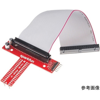
SparkFun Pi Wedge
SPARKFUN¥4,898税込¥5,3881個33日以内出荷Description。This is the SparkFun Pi Wedge, a small board that connects to the 40-pin GPIO connector on the Raspberry Pi and breaks the pins out to breadboard-friendly arrangement and spacing, and even adds a couple of decoupling capacitors on the powerアズワン品番67-0419-89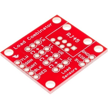
SparkFun Load Sensor Combinator
SPARKFUN¥839税込¥9231個33日以内出荷Description。The SparkFun Load Sensor Combinator is a bare PCB that combines four load sensors into a standard four-wire Wheatstone bridge configuration. If you open up an electronic bathroom scale, you'll find a large rat's nest of wires. The Load Sensor Combinator was created to combine the 12 wires found in a bathroom scale into the standard four-wire Wheatstone bridge configuration.。This version of the SparkFun Load Sensor Combinator features a few changes that you specifically asked for! We updated the silk on the breakout to read "C/+/-" instead of "R/W/B" and moved the temperature sensor connector away from the standoff hole.。You can either use four individual load sensors or simply purchase an off-the-shelf bathroom scale and hack the combinator into it rather than trying to design a base to properly mount four load sensors.。This board works great with our Load Cell Amplifier breakout board; the five pins on the edge of the combinator line up directly to the five pins on the amplifier.。If your amplifier and supporting electronics are more than a few inches away from the scale, an RJ45 footprint is provided. The four Wheatstone pins(E+/E-/S+/S-)as well as the shield pin are connected to twisted pairs within a standard cheap Ethernet cable. This allows the amplifier board to be placed many feet away from the scale itself.。The combinator board also includes a footprint for the DS18B20 one-wire temperature sensor. This allows the user to gather the temperature of the scale in case there is a large variance between the scale and the amplifier. These three pins are accessed through the RJ45 connection as well, allowing remote temperature readings to be gathered over one twisted pair Ethernet cable.。NOTE:。The SparkFun Load Sensor Combinator will only work with 3 wire load sensors, it is not compatible with 4 wire load cells.アズワン品番67-0419-93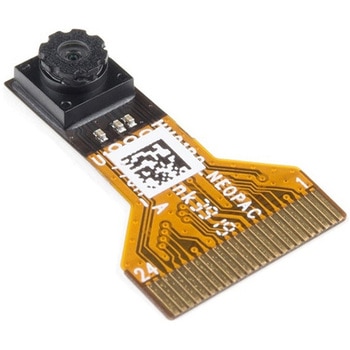
Himax CMOS Imaging Camera - HM01B0
SPARKFUN¥3,698税込¥4,0681個33日以内出荷。Description。The HM01B0 from Himax Imaging is an ultra low power CMOS Monochrome Image Sensor that enables the integration of an "Always On" camera for computer vision applications such as gestures, intelligent ambient light and proximity sensing, tracking and object identification. The sensor allows the sensor to consume very low power of <2mW at QVGA 30FPS. This low power consumption and vision applications camera comes with a ribbon cable that mates to the camera connector populated on the following products:MicroMod Machine Learning Carrier Board。Artemis Development Kit。Edge Development Board - Apollo3 Blue。The HM01B0 contains 320×320 pixel resolution and supports a 320×240 window mode which can be readout at a maximum frame rate of 60FPS, and a 2×2 monochrome binning mode with a maximum frame rate of 120FPS. The video data is transferred over a configurable 1bit, 4bit or 8bit interface with support for frame and line synchronization. The sensor integrates black level calibration circuit, automatic exposure and gain control loop, self-oscillator and motion detection circuit with interrupt output to reduce host computation and commands to the sensor to optimize the system power consumption.。Features。Image Sensor。Ultra Low Power Image Sensor(ULPIS)designed for Always On vision devices and applications。High sensitivity 3.6μ BrightSenseTM pixel technology。320×320 active pixel resolution with support for QVGA window, vertical flip and horizontal mirror readout。Programmable black level calibration target, frame size, frame rate, exposure, analog gain(up to 8x)and digital gain(up to 4x)。Automatic exposure and gain control loop with support for 50 / 60Hz flicker avoidance。Flexible 1bit, 4bit and 8bit video data interface with video frame and line sync。Motion Detection circuit with programmable ROI and detection threshold with digital output to serve as an interrupt。On-chip self oscillator。I2C 2-wire serial interface for register access。High CRA for low profile module design。Sensor Parameters。Active Pixel Array 320×320。Pixel Size 3.6 μm×3.6 μm。Full Image Area 1152 μm×1152 μm。Diagonal(Optical Format)1.63 mm(1/11″)。Scan Mode:Progressive。Shutter Type:Electronic Rolling Shutter。Frame Rate MAX 51 fps @ 320×320, 60 fps @ 320×240(QVGA)。CRA(maximum)30℃。Sensor Specifications。Supply Voltage:Analog - 2.8 V, Digital - 1.5V(Internal LDO:1.5V - 2.8V), I/O - 1.5 - 2.8V。Input Reference Clock:3 - 50 MHz。Serial Interface(I2C):2-wire, 400 KHz max.。Video Data Interface:1b, 4b, 8b with frame / line SYNC。Output Clock Rate MAX:50 MHz for 1bit, 12.5 MHz for 4bit, 6.25 MHz for 8bit。Est. Power Consumption(include IO with 5pF load):QVGA 60FPS(Typical)<4 mW。QVGA 30FPS(Typical)<2 mWアズワン品番67-0427-08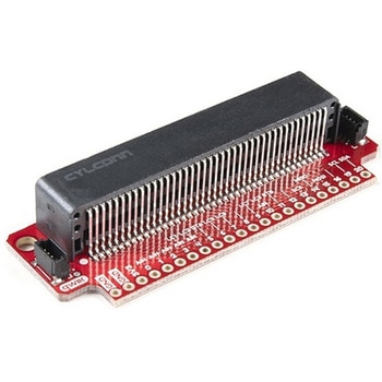
SparkFun Qwiic micro:bit Breakout
SPARKFUN¥1,898税込¥2,0881個33日以内出荷Description。The SparkFun Qwiic micro:bit Breakout is a board that connects to the BBC micro:bit and expands the capabilities of the development platform by providing access to more pins and allowing for connections to the I2C and SPI buses. This breakout board for the micro:bit's edge connector allows intermediate and advanced users to connect the micro:bit to breadboards and other Qwiic sensors, motors, LEDs and more.。The micro:bit on its own has three digital/analog input/output rings available for you to use initially with alligator clips. With the micro:bit Breakout we have broken out all 21 GPIO, power and ground-to-pin outs in a 0.1" formation and with two individual Qwiic Connectors. With this breakout you will be able to unlock the full potential of your micro:bit!。Note:。No micro:bit or headers are included with this breakout; they will need to be purchased separately. If you would like a micro:bit breakout with headers already soldered on, be sure to check out this board's sibling.。The SparkFun Qwiic Connect System is an ecosystem of I2C sensors, actuators, shields and cables that make prototyping faster and less prone to error. All Qwiic-enabled boards use a common 1mm pitch, 4-pin JST connector. This reduces the amount of required PCB space, and polarized connections mean you can't hook it up wrong.。Get Started with the Qwiic micro:bit Breakout Guideアズワン品番67-0420-12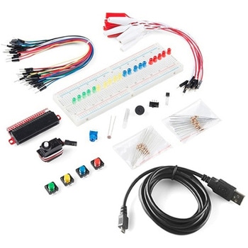
SparkFun Inventor's Kit Bridge Pack for micro:bit
SPARKFUN¥15,980税込¥17,5781個33日以内出荷Description。Do you own micro:bit or micro:bit Go Bundle and want to expand your skills with the new microcontroller? You are in luck! The SparkFun Inventor's Kit Bridge Pack for micro:bit was designed to provide you with an easy way to transform your m:b into full fledged learning kit! Each Bridge Pack includes all of the parts found in the SIK for micro:bit that aren't included with the Go Bundle. With the SIK Bridge Pack for micro:bit you will be able to complete circuits that will teach you how to read sensors, move motors, build Bluetooth(R)devices and more.。The micro:bit is pocket-sized computer that lets you get creative with digital technology. Between the micro:bit and our shield-like bit boards you can do almost anything while coding, customizing and controlling your micro:bit from almost anywhere! You can use your micro:bit for all sorts of unique creations, from robots to musical instruments and more. At half the size of credit card, this versatile board has vast potential!。Note:The Bridge Pack is NOT full SparkFun Inventor's Kit and only includes the parts to complement micro:bit Go Bundle or standalone board. That also means that this kit does。not。include micro:bit, which will need to be purchased separately.。Get started with the micro:bit SIK Experiment Guide。Examples。Circuit 0:Hello, micro:bit!。Circuit 1:Blinking an LED。Circuit 2:Reading Potentiometer。Circuit 3:Reading Photoresistor。Circuit 4:Driving an RGB LED。Circuit 5:Reading an SPDT Switch。Circuit 6:Reading Button Press。Circuit 7:Reading the Temperature Sensor。Circuit 8:Using Servo Motor。Circuit 9:Using Buzzer。Circuit 10:Using the Accelerometer。Circuit 11:Using the Compassアズワン品番67-0424-21