カテゴリ
- 学童・教育用品(9)
絞り込み
ブランド
- SPARKFUN
- モノタロウ(21)
- VISHAY(25)
- BOURNS(21)
- SMC(19)
- D'Addario(18)
- U-KANAYA(16)
- YKK AP(12)
- Festo(12)
- brembo(9)
- DEDA ELEMENTI(7)
- プロト(4)
- RS PRO(4)
- NACHI(不二越)(3)
- PROMOTE(プロモート)(3)
- ホーザン(3)
- ホンダ(3)
- EKチェーン(3)
- ASUS(エイスース)(3)
- ミツビシ(3)
- ブランドをもっと見る
「crv」の検索結果
特価
 の全商品がキャンペーンコード入力で通常価格より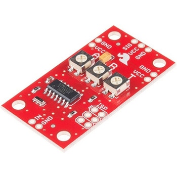
SparkFun Servo Trigger - Continuous Rotation
SPARKFUN¥4,898税込¥5,3881個33日以内出荷。Description。The SparkFun Continuous Rotation(CR)Servo Trigger is a small robotics board that simplifies the control of hobby RC servo motors. When an external switch or logic signal changes state, the CR Servo Trigger is able to tell an attached servo motor to move from position A to position B. To use the CR Servo Trigger, you simply connect a hobby servo and a switch, then use the on-board potentiometers to adjust the start/stop positions and the transition time. You can use a hobby servo in your projects without having to do any programming!。When we introduced the original Servo Trigger, we mentioned that it could be reprogrammed to be more useful with continuous rotation servo motors. But reprogramming the firmware is somewhat tedious, and users asked for a Servo Trigger preprogrammed with the continuous rotation logic. With this little board you will be provided an easy way to deploy continuous rotation servos into your projects!。The heart of the CR Servo Trigger is an Atmel ATtiny84 microcontroller, running a small program that implements the servo control features designed for continuous rotation servos. On board each of these CR Servo Triggers you will find three potentiometers:"A" sets the position the servo sits in while the switch is open, "B" sets the position the servo moves to when the switch is closed, and "T" sets the time it takes to get from A to B and back.。Compared with a servo motor, the CR Servo Trigger board draws very little current, roughly 5mA at 5V. Be sure to note that if you're using the CR Servo Trigger to control your motor, the absolute maximum supply voltage that should be applied is 5.5 VDC. Additionally, the SparkFun CR Servo Trigger is designed to make it easy to daisy chain boards - you can simply connect the VCC and GND pads on adjacent boards to each other.。Note:This idea originally came from our friend in the Oakland area, CTP. If you see him, please give him a high-five for us.。SparkFun CR Servo Trigger Hookup Guide。Features。Recommended Voltage:5VDC。Max Voltage:5.5VDC。Current Draw:5mA。Control Continuous Rotation Servos。Three Control Settings。A - sets the position the servo sits in while the switch is open。B - sets the position the servo moves to when the switch is closed。C - sets the time it takes to get from A to B and back。Easy Control with Potentiometers。Configurable Input Polarity。Configurable Response Mode。Compatible with Analog Servos。ISP Header Pins Available for Reprogramアズワン品番67-0429-21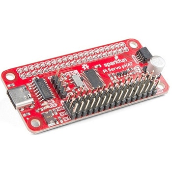
SparkFun Servo pHAT for Raspberry Pi
SPARKFUN¥4,298税込¥4,7281個33日以内出荷Description。The SparkFun Servo pHAT for Raspberry Pi allows your Raspberry Pi to control up to 16 servo motors in a straightforward and uncomplicated manner via an I2C connection. Thanks to its I2C capabilities, this PWM HAT saves the Raspberry Pi's GPアズワン品番67-0422-77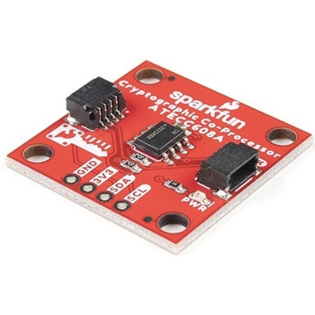
SparkFun Cryptographic Co-Processor Breakout - ATECC608A Qwiic
SPARKFUN¥1,498税込¥1,6481個33日以内出荷。Description。Product Restrictions:To access certain features of the ATECC608A, users will need to contact Microchip and sign an NDA contract to obtain the complete datasheet. Due to the required NDA - technical support, an Arduino library, and hookup guide are not provided for users on this product.。The SparkFun ATECC608A Cryptographic Co-processor Breakout allows you to add strong security to your IoT node, edge device, or embedded system. This includes。a。symmetric。authentication,。symmetric。AES-128 encryption/decryption, and much more. As stated above, the ATECC608A has limited Arduino support and the complete datasheet is under NDA with Microchip.。This breakout board includes two Qwiic ports for plug and play functionality. Utilizing our handy Qwiic system, no soldering is required to connect it to the rest of your system. However, we still have broken out 0.1"-spaced pins in case you prefer to use a breadboard. The ATECC608A chip is capable of many cryptographic processes, including, but not limited to:Creating and securely storing unique asymmetric key pairs based on Elliptic Curve Cryptography(FIPS186-3).。AES-128:Encrypt/Decrypt, Galois Field Multiply for GCM。Creating and verifying 64-byte digital signatures(from 32-bytes of message data).。Creating a shared secret key on a public channel via Elliptic Curve Diffie-Hellman Algorithm.。SHA-256 HMAC Hash including off-chip context save/restore。Internal high quality FIPS random number generator.。Embedded in the chip is a 10Kb EEPROM array that can be used for storing keys, certificates, data, consumption logging, and security configurations. Access to the sections of memory can then be restricted and the configuration locked to prevent changes. Each ATECC608A Breakout ships with a guaranteed unique 72-bit serial number and includes several security features to prevent physical attacks on the device itself, or logical attacks on the data transmitted between the device.。A summary datasheet for the ATECC608A is available here. The full datasheet is under NDA with Microchip. You will need to contact them for access to the entire datasheet. Meanwhile, the ArduinoATECCX08 Library currently only supports the ATECC608A with SAMD21 Arduino boards.。We do have much more support for the ATECC508A version of this chip. Please check out our ATECC508A Hookup Guide and Arduino Library(which includes six examples). This will get you familiar with the basics of elliptic curve cryptography and signing/verifying data with the ATECC508A version of the chip.。Note:The I2C address of the ATECC608A is 0x60 and is software-configurable to any address. A multiplexer/Mux is required to communicate to multiple ATECC608A sensors at the default address when on a single bus. If you need to use more than one ATECC608A sensor at the default address, consider using the Qwiic Mux Breakout.。Note:The ATECC608A can be only configured once before it is。PERMANENTLY。locked。. It is advisable that users purchase multiple boards in order to use other configurations and explore the advanced functions of the ATECC608A.。Additionally, this board。IS。capable of encrypting and decrypting data. However, to access these additional features, you will need to contact Microchip and sign an NDA contract to obtain the complete datasheet.。It is recommended that an SparkFun RedBoard Turbo - SAMD21 Development Board is used with this product due to the buffer size required on the I2C bus.。The SparkFun Qwiic Connect System is an ecosystem of I2C sensors, actuators, shields and cables that make prototyping faster and less prone to error. All Qwiic-enabled boards use a common 1mm pitch, 4-pin JST connector. This reduces the amount of required PCB space, and polarized connections mean you can't hook it up wrong.。。Features。Operating Voltage:2.0V-5.5V(。Default on Qwiic System:3.3V。)。Active Current Draw(for ATECC608A):16 mA。Sleep Current(for ATECC608A):<150 nA。Guaranteed Unique 72-bit Serial Number。10 Kb EEPROM Memory for Keys, Certificates, and Data。Storage for up to 16 Keys。256-bit Key Length。Internal High-Quality FIPS Random Number Generator(RNG)。Configurable I2C Address(7-bit):0x60(。Default。)アズワン品番67-0423-59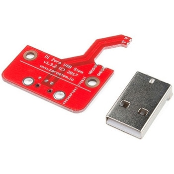
Pi Zero USB Stem
SPARKFUN¥3,398税込¥3,7381個33日以内出荷Description。The Pi Zero USB Stem is a PCB kit that turns a Raspberry Pi Zero into a USB dongle. Once the Stem is installed, your Raspberry Pi can be plugged directly into a computer or USB hub without any additional cables or power supplies. The Raspberry Pi then acts as a USB device using its own Linux kernel gadget drivers to get started.。The Zero Stem is designed to be soldered directly to the USB SMD test pads on the bottom of the Raspberry Pi Zero, needing no wires or pogo pins at all, just solder and a soldering iron! Attaching the stem to your Pi also allows you to create a portable VNC server, or even cluster several Raspberry Pi Zeros with just a USB hub.。The Zero Stem is compatible with the Raspberry Pi Zero v1.3 and the Raspberry Pi Zero W v1.1, but unfortunately it is not compatible with the Raspberry Pi Zero v1.2 or any full-size Raspberry Pi due to their shapes and sizes.。Note:In order for your Pi Zero to function as a USB device with this Stem, you will need to configure it to act as one. You will be able to find these instructions in the Documentations tab under "How to OTG Fast".アズワン品番67-0424-13
Actuonix PQ12-100-6-R Micro-Actuator
SPARKFUN¥47,980税込¥52,7781個33日以内出荷Description。The PQ12 series of micro linear actuators are ideal for applications requiring precise positioning and compact size. Weighing in at just 22 grams, the PQ12 is incredibly light as well as compact. The affordably-priced PQ12 is the most powerful actuator of it's size. This is why it has become a popular choice for OEM manufacturers as well as Arduino and RC hobbyists. Some industries where the PQ12 are in use include:prosthetics, robotics, medical, simulation.。The PQ12-R series of linear servos operate as a direct replacement for standard rotary servos. They use the same standard 3 wire connector, ground power and control. Regardless of how you drive your servos, be it with an RC receiver, an Arduino board, or a VEX micro-controller, the PQ12-R servo will function in place of a regular servo, but with the added benefit of providing linear motion. The PQ12-R is available in a 20mm stroke coupled with gear ratio options of 30:1, 63:1 and 100:1 cover a large variety of applications.。The PQ12-100-6-R has:a 100:1 gear ratio for maximum lifting force; 6VDC operating voltage; and a servo(PWM)interface. This powerful little actuator can lift 50N(~5kg)!。The datasheet doesn't mention a minimum operating voltage, but we've tested this actuator at 5VDC and it seems to work just fine. The maximum force and movement speed are reduced of course.。Features。Gearing Option:100:1。Peak Power Point:40N @ 6mm/s。Peak Efficiency Point:20N @ 8mm/s。Max Speed(no load):10mm/s。Max Force(lifted):50N。Max Side Load:10N。Back Drive Force:35N。Stroke:20 mm。Input Voltage:6 VDC。Stall Current:550mA @ 6V。Mass:22g。Operating Temperature -10℃ to +50℃。Positional Repeatability:±0.1mm。Mechanical Backlash:0.25 mm。Audible Noise:55dB @ 45cm。Ingress Protection:IP-54。Maximum Duty Cycle:20%。PWM(Servo)signal:Fully retracted:2.0ms @ 50Hz。Fully extended:1.0ms @ 50Hzアズワン品番67-0426-44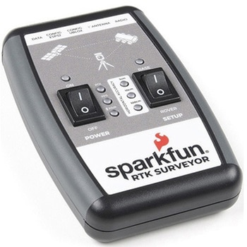
SparkFun RTK Surveyor
SPARKFUN¥129,800税込¥142,7801個33日以内出荷Description。The SparkFun RTK Surveyor is an easy to use GNSS receiver for centimeter-level positioning. Perfect for surveying, this preprogrammed device can also be used for autonomous driving, navigation, asset tracking and any other application where there is a clear view of the sky. The RTK Surveyor can also be used as a base station. With the flick of a switch, two RTK Surveyors can be used to create an RTK system capable of 14mm horizontal positional accuracy. The built-in Bluetooth(R)connection via an ESP32 WROOM enables the user to use the RTK Surveyor with their choice of GIS application on a phone or tablet. The built in battery allows field use for up to four hours and is compatible with common USB battery banks.。This device can be used in four modes:GNSS Positioning(~30cm accuracy)。GNSS Positioning with RTK(1.4cm accuracy)。GNSS Base Station。GNSS Base Station NTRIP Server。In Position mode the device receives L1/L2 signals from a user-provided antenna and the high-grade GNSS receiver provides lat/long and altitude with accuracies around 300mm.。In Positioning with RTK mode the device receives L1/L2 signals from the antenna and correction data from a base station. The correction data can be obtained from a cellular link to online correction sources or over a radio link to a 2nd RTK Surveyor setup as a base station.。In Base Station mode the device is mounted to a temporary position(like a tripod)and begins transmitting correction data over a radio or internet connection. A base is often used in conjunction with a second unit set to 'Positioning with RTK' to obtain the 14mm relative accuracy.。In Base Station NTRIP Server mode the device is mounted to a semi or permanently fixed position(like a roof)and connects over WiFi to transmit the correction data to a NTRIP caster so that any rover can access the correction data over a cellular or internet connection. This type of base is a very easy way to setup a very precise absolute correction source.。Two cables are provided with the RTK Surveyor allowing a user to plug on our easy to use Serial Telemetry Radios or their own radio link. If a local correction source is within 10km, a user can also use their phone to provide correction data over the Bluetooth(R)link(no external radio needed!).。Note:The SparkFun RTK Surveyor is just the enclosed device and does NOT include an antenna, serial telemetry radio, or associated mounting pieces. These items will need to be purchased separately from the Hookup Accessories below.。Get Started With the SparkFun RTK Surveyor Guide。Features。GNSS Receiver:ZED-F9P。Concurrent reception of GPS, GLONASS, Galileo and BeiDou。Receives both L1C/A and L2C bands。Current:68mA - 130mA(varies with constellations and tracking state)。Time to First Fix:25s(cold), 2s(hot)。Max Navigation Rate:PVT(basic location over UBX binary protocol)- 25Hz。RTK - 20Hz。Raw - 25Hz。Horizontal Position Accuracy:2.5m without RTK。0.010m with RTK。Max Altitude:50km(31 miles)。Max Velocity:500m/s(1118mph)。Bluetooth(R)Transceiver:ESP32 WROOM。Xtensa(R)dual-core 32-bit LX6 microprocessor。Up to 240MHz clock frequency。16MB of flash storage。520kB internal SRAM。Integrated 802.11 BGN WiFi transceiver。Integrated dual-mode Bluetooth(R)(classic and BLE)。Hardware accelerated encryption(AES, SHA2, ECC, RSA-4096)。2.5 μA deep sleep current。Overall Device。Internal Battery:LiPo 1000mAh with 500mA charging。Radio Port:3.3V TTL Serial(57600bps RTCM TX/RX)。Data Port:3.3V TTL Serial(115200bps NMEA)。Weight:132g(entire device including battery)。Dimensions:118mm×79mm×30mm(4.7in×3.1in×1.2in)。1x Qwiic Connector。1x microSD Socket for optional logging。Changes:This version(which replaces SPX-17369)uses a reinforced edge mount SMA connector for better resiliency when a fixed 'stub' antenna is used.アズワン品番67-0423-95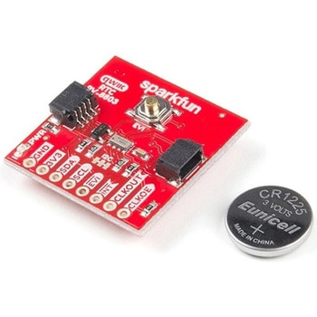
SparkFun Real Time Clock Module - RV-8803 Qwiic
SPARKFUN¥5,798税込¥6,3781個33日以内出荷。Description。The SparkFun RV-8803 Real Time Clock Module is a Qwiic-enabled breakout board for the RV-8803 RTC. The RV-8803 boasts some impressive features including a temperature compensated crystal providing extremely precise time-keeping, low power consumption, and time stamp event input along with a user-programmable timing offset value. The RV-8803 also has an improved I2C interface compared to the RV-1805 RTC that removes the need to sequence commands/writes to the device. Best of all, the temperature compensation comes factory calibrated. Utilizing our handy Qwiic system so no soldering is required to connect it to the rest of your system. However, we still have broken out 0.1"-spaced pins in case you prefer to use a breadboard.。Adding a real-time clock to your project is the perfect way to get more accurate data; timing or otherwise. Using the Qwiic connector makes for a fast, solid way to incorporate this into your project. The RTC module has counters for hundredths of seconds, seconds, minutes, hours, date, month, year and weekday with a number of alarm and interrupt settings available as well. Plus the large operating temperature range(-40 to +105℃)and temperature compensated crystal makes for a good addition for field applications or harsh environments.。The SparkFun Qwiic Connect System is an ecosystem of I2C sensors, actuators, shields and cables that make prototyping faster and less prone to error. All Qwiic-enabled boards use a common 1mm pitch, 4-pin JST connector. This reduces the amount of required PCB space, and polarized connections mean you can't hook it up wrong.。Get Started with the SparkFun RV-8803 Real Time Clock Module Guide。Features。Factory Calibrated Temperature Compensation。High Time Accuracy。±1.5 ppm 0 to +50℃。±3.0 ppm -40 to +85℃。±7.0 ppm +85 to +105℃。1.5V to 5.5V Operating Voltage Range。240nA @ 3.3v Low-Power Consumption。I2C Address:0x32。Periodic Countdown Timer Interrupt function。Periodic Time Update Interrupt function(seconds, minutes)。Alarm Interrupts for weekday or date, hour and minute settings。External Event Input with Interrupt and Time Stamp function。Programmable Clock Output pin for peripheral devices.。Operating temperature range:-40 to +105℃。2x Qwiic Connectorsアズワン品番67-0420-10