カテゴリ
- 学童・教育用品(7)
絞り込み
ブランド
- SPARKFUN
- D'Addario(346)
- オカムラ(岡村製作所)(38)
- StarTech.com(14)
- ホームテイスト(6)
- MAZDA(マツダ)(5)
- SMC(4)
- Panasonic(パナソニック)(4)
- ホンダ(4)
- LION (ライオン事務器)(4)
- Dahua(ダーファ・テクノロジー)(3)
- Gefen(3)
- オーム電機(2)
- 岡崎精工(2)
- 小澤物産(OZC)(2)
- イトーキ(2)
- メディアカバーマーケット(2)
- I ・O DATA(アイ・オー・データ)(1)
- NSK(日本精工)(1)
- ブランドをもっと見る
「ddw」の検索結果
 Alchitry Cu FPGA Development Board Lattice iCE40 HXSPARKFUN
¥15,980税込¥17,578
1個
33日以内出荷
DescriptionIf you are not needing a lot of power to start your FPGA adventure, or are looking for a more economical option, the Alchitry Cu FPGA Development Board might be the perfect option for you! The Alchitry Cu is a "lighter" FPGA version than the Alchitry Au but still offers something completely unique. FPGAs, or Field-Programmable Gate Arrays, are an advanced development board type for engineers and hobbyists alike to experience the next step in programming with electronics. The Cu truly exemplifies the trend of more affordable and increasingly powerful FPGA boards arriving each year. This board is a fantastic starting point into the world of FPGAs and the heart of your next project. Finally, now that this board is built by SparkFun, we added a Qwiic connector for easy I2C integration!The Alchitry Cu uses the Lattice iCE40 HX FPGA with 7680 logic cells and is supported by the open source tool chain Project IceStorm. The Cu possesses 79 IO pins with eight general purpose LEDs; a 100MHz on-board clock that can be manipulated internally by the FPGA; a USB-C connector to configure and power the board; and a USB to serial interface for data transfer.By adding stackable expansion boards similar to shields or HATs called "Elements," the Alchitry Cu is able to expand its own hardware capabilities by adding prototyping spaces, buttons, LEDs, and more!The SparkFun Qwiic Connect System is an ecosystem of I2C sensors, actuators, shields and cables that make prototyping faster and less prone to error. All Qwiic-enabled boards use a common 1mm pitch, 4-pin JST connector. This reduces the amount of required PCB space, and polarized connections mean you can't hook it up wrong.Get Started with our Learning FPGA TutorialsFeaturesLattice iCE40-HX8K FPGA - 7680 logic elements79 IO pins(3.3V logic level)USB-C to configure and power the boardEight general purpose LEDsOne button(typically used as a reset)100MHz on-board clock(can be multiplied internally by the FPGA)Powered with 5V through USB-C port, 0.1" holes, or headersUSB to serial interface for data transfer(up to 12Mbaud)Qwiic ConnectorDimensions of 65mm×45mmExamplesFirst FPGA Project - Getting Fancy with PWMExternal IO and Metastability
アズワン品番67-0423-08
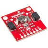
 SparkFun Real Time Clock Module - RV-1805 QwiicSPARKFUN
¥7,798税込¥8,578
1個
33日以内出荷
DescriptionGet with the times, already! This SparkFun Real Time Clock(RTC)Module is a Qwiic-enabled breakout board for the RV-1805 chipset. The RTC is ultra-low power(running at only about 22nA in its lowest power setting)so it can use a supercapacitor for backup power instead of a normal battery. This means you get plenty of charge and discharge cycles without any degradation to the "battery." To make it even easier to get your readings, all communication is enacted exclusively via I2C, utilizing our handy Qwiic system so no soldering is required to connect it to the rest of your system. However, we still have broken out 0.1"-spaced pins in case you prefer to use a breadboard.This RTC module's built in RV-1805 has not one, but two internal oscillators:a 32.768kHz tuning fork crystal and a low power RC based oscillator and can automatically switch between the two using the more precise crystal to correct the RC oscillator every few minutes. This feature allows the module to maintain a very accurate date and time with the worst case being +/- about three minutes over a year. The RV-1805 also has a built in trickle charger so as soon as the RTC is connected to power the it will be fully charged in under 10 minutes and has the ability to switch power to other systems allowing it to directly turn on or off a power hungry device such as a microcontroller or RF engine.There is also the option to add a battery to the board if the supercapacitor just isn't going keep your project powered long enough(keep in mind, the supercap can hypothetically make the board keep time for around 35 days), you can solder on an external battery. That means you can let board sit with no power or connection to the outside world and the current hour/minute/second/date will be maintained.Note:The I2C address of the RV-1805 is 0x69 and is hardware defined. A multiplexer/Mux is required to communicate to multiple RV-1805 sensors on a single bus. If you need to use more than one RV-1805 sensor consider using the Qwiic Mux Breakout.The SparkFun Qwiic connect system is an ecosystem of I2C sensors, actuators, shields and cables that make prototyping faster and less prone to error. All Qwiic-enabled boards use a common 1mm pitch, 4-pin JST connector. This reduces the amount of required PCB space, and polarized connections mean you can't hook it up wrong.Get Started with the RV-1805 Real Time Clock Module GuideFeaturesOperating Voltage(Startup):1.6V - 3.6VOperating Voltage(Timekeeping):1.5V - 3.6VOperating Temperature:-40℃ - 85℃Time Accuracy:±2.0 ppmCurrent Consumption:22nA(Typ.)I2C Address:0xD2Supercapacitor for Backup Power2x Internal Oscillators2x Qwiic Connectors
アズワン品番67-0420-02
 SparkFun Capacitive Touch Slider - CAP1203 QwiicSPARKFUN
¥2,498税込¥2,748
1個
33日以内出荷
DescriptionDo you want to replace a slider or a button on your art project or science experiment with a more interesting interface? This Capacitive Touch Slider is a "Qwiic" and easy way to add capacitive touch to your next project. With the board's built in touch pads, you can immediately start playing with the touch capabilities as three unique touch inputs or as a slider. You can also enable a touch input to act as a power button, customize the sensitivity for your own touch pads, and play with the interrupt alert LED. Utilizing our Qwiic system, no soldering is required to connect it to the rest of your system. However, we have broken out 0.1"-spaced pins in case you prefer to use a breadboard or create your own touch pads.On the front of the board, there is an arrow shape which contains three separate capacitive touch pads. We also broke out the capacitive touch sensor lines as plated through-holes on the top of the board. You can use these pins to connect to your own capacitive touch pads. The CS1 pin connects to the left pad, the CS2 pin connects to the middle pad, and the CS3 pin connects to the right pad.NOTE:The I2C address of the CAP1203 is 0x28 and is hardware defined. A multiplexer/Mux is required to communicate to multiple CAP1203 sensors on a single bus. If you need to use more than one CAP1203 sensor consider using the Qwiic Mux Breakout.The SparkFun Qwiic connect system is an ecosystem of I2C sensors, actuators, shields and cables that make prototyping faster and less prone to error. All Qwiic-enabled boards use a common 1mm pitch, 4-pin JST connector. This reduces the amount of required PCB space, and polarized connections mean you can't hook it up wrong.Get Started with the SparkFun Capacitive Touch Slider GuideFeaturesCapacitive Touch3 unique capacitive touch inputsFeaturesEmulated sliderPower button settingProgrammable sensitivityAutomatic recalibrationI2C Address:0x28Qwiic EnabledOperating RangeSupply Voltage:3.3V - 5V
アズワン品番67-0427-06
 SparkFun IR Array Breakout - 110 Degree FOV, MLX90640 QwiicSPARKFUN
¥22,980税込¥25,278
1個
33日以内出荷
DescriptionIt's time to say hip hip array for this IR Breakout! The MLX90640 SparkFun IR Array Breakout is equipped with a 32x24 array of thermopile sensors creating, in essence, a low resolution thermal imaging camera. With this breakout you can detect surface temperatures from many feet away with an accuracy of ±1.5℃(best case). To make it even easier to get your low-resolution infrared image, all communication is enacted exclusively via I2C, utilizing our handy Qwiic system. However, we still have broken out 0.1"-spaced pins in case you prefer to use a breadboard.This specific IR Array Breakout features a 110°x75° field of view with a temperature measurement range of -40℃-300℃. The MLX90640 IR Array has pull up resistors attached to the I2C bus; both can be removed by cutting the traces on the corresponding jumpers on the back of the board. Please be aware that the MLX90640 requires complex calculations by the host platform so a regular Arduino Uno(or equivalent)doesn't have enough RAM or flash to complete the complex computations required to turn the raw pixel data into temperature data. You will need a microcontroller with 20,000 bytes or more of RAM. To achieve this, we recommend a Teensy 3.1 or above.Note:The I2C address of the MLX90640 is 0x33 and is hardware defined. A multiplexer/Mux is required to communicate to multiple MLX90640 sensors on a single bus. If you need to use more than one MLX90640 sensor consider using the Qwiic Mux Breakout.The SparkFun Qwiic connect system is an ecosystem of I2C sensors, actuators, shields and cables that make prototyping faster and less prone to error. All Qwiic-enabled boards use a common 1mm pitch, 4-pin JST connector. This reduces the amount of required PCB space, and polarized connections mean you can't hook it up wrong.Get Started with the SparkFun IR Array Breakout GuideFeaturesOperating Voltage:3V-3.6VCurrent Consumption:~18mAField of View:110°x75°Measurement Range:-40℃-300℃Resolution:±1.5℃Refresh Rate:0.5Hz-64HzI2C Address:0x332x Qwiic Connection Ports
アズワン品番67-0426-87
 SparkFun Spectral Sensor Breakout - AS7263 NIR QwiicSPARKFUN
¥9,998税込¥10,998
1個
33日以内出荷
DescriptionThe SparkFun AS7263 Near Infrared(NIR)Spectral Sensor Breakout brings spectroscopy to the palm of your hand, making it easier than ever to measure and characterize how different materials absorb and reflect different wavelengths of light. The AS7263 Breakout is unique in its ability to communicate by both an I2C interface and serial interface using AT commands. Hookup is easy, thanks to the Qwiic connectors attached to the board --- simply plug one end of the Qwiic cable into the breakout and the other into one of the Qwiic shields, then stack the board on a development board. You'll be ready to upload a sketch to start taking spectroscopy measurements in no time.The AS7263 spectrometer detects wavelengths in the visible range at 610, 680, 730, 760, 810 and 860nm of light, each with 20nm of full-width half-max detection. The board also has multiple ways for you to illuminate objects that you will try to measure for a more accurate spectroscopy reading. There is an onboard LED that has been picked out specifically for this task, as well as two pins to solder your own LED into.Note:The I2C address of the AS7263 is 0x49 and is hardware defined. A multiplexer/Mux is required to communicate to multiple AS7263 sensors on a single bus. If you need to use more than one AS7263 sensor consider using the Qwiic Mux Breakout.The SparkFun Qwiic Connect System is an ecosystem of I2C sensors, actuators, shields and cables that make prototyping faster and less prone to error. All Qwiic-enabled boards use a common 1mm pitch, 4-pin JST connector. This reduces the amount of required PCB space, and polarized connections mean you can't hook it up wrong.Get Started with the SparkFun AS726X Spectral Sensor Breakout GuideFeatures6 near-IR channels:610nm, 680nm, 730nm, 760nm, 810nm and 860nm, each with 20nm FWHMNIR filter set realized by silicon interference filters16-bit ADC with digital accessProgrammable LED drivers2.7V to 3.6V with I2C interface2x Qwiic connectors
アズワン品番67-0426-70
 SparkFun Raspberry Pi 4 Hardware Starter Kit - 4GBSPARKFUN
¥56,980税込¥62,678
1個
33日以内出荷
DescriptionThe Raspberry Pi 4 Hardware Starter Kit provides a solid set of parts and instruction for working with the Raspberry Pi 4 in a more hardware-centric manner. While the Raspberry Pi isn't typically considered a go-to for hardware projects, its I/O pins hold a lot of benefits that you can use for a variety of applications. This kit covers the basics like using LEDs, and Buttons while providing a solid set of parts for working with any other hardware I/O and the 40-pin header. In addition, we've included all the parts needed for getting the Raspberry Pi 4 up and running whether it's on its own, or using a monitor(not included). The new 64GB MicroSD cards keep read/write commands running super fast, too.Most of the contents of the kit rely on the use of the 2x20, 40-pin header, so we've included a special extender to allow you to plug in the ribbon cable while using the provided heatsink case. We've also included a Qwiic Shim for easily working with I2C based Qwiic boards with the Pi. No soldering is required for this kit!Note:This variation includes the 4GB RAM option for the Raspberry Pi 4.Get Started with the Raspberry Pi 4 Model B Guide
アズワン品番67-0424-46
 I/O Expander - MCP23008SPARKFUN
¥639税込¥703
1個
33日以内出荷
DescriptionAdd another eight pins to your microcontroller using a MCP23008 port expander. The MCP23008 uses two I2C pins which can be shared with other I2C devices, and in exchange gives you eight general purpose pins. You can set each of eight pins to be input, output, or input with a pullup. There's even the ability to get an interrupt via an external pin when any of the inputs change so you don't have to keep polling the chip.Use this chip from 2.7-5.5V(good for any 3.3V or 5V setup), and you can sink/source up to 20mA from any of the I/O pins so this will work for LEDs and such. Team it up with a high-power MOSFET if you need more juice. DIP package means it will plug into any breadboard or perfboard.You can set the I2C address by tying the ADDR0-2 pins to power or ground, for up to eight unique addresses. That means eight chips can share a single I2C bus - that's 64 I/O pins!Features8-bit remote bidirectional I/O portHigh-speed I2C interface(MCP23008)Hardware address pinsConfigurable interrupt output pinConfigurable interrupt sourcePolarity Inversion register for input port data polarity config.External reset inputLow standby current:1 μA(max.)・ Operating voltage:1.8V to 5.5V @ -40℃ to +85℃ I2C @ 100 kHz SPI @ 5 MHz2.7V to 5.5V @ -40℃ to +85℃ I2C @ 400 kHz SPI @ 10 MHz4.5V to 5.5V @ -40℃ to +125℃ I2C @ 1.7 kHz SPI @ 10 MHz
アズワン品番67-0421-32