カテゴリ
- 学童・教育用品(4)
絞り込み
ブランド
- SPARKFUN
- モノタロウ(3)
- ENGINEER(エンジニア)(1)
- goot(太洋電機産業)(6)
- HAKKO(白光)(5)
- RS PRO(5)
- SICK(1)
- サンハヤト(1)
- ホーザン(3)
- 東信工業(1)
「goot wick」の検索結果
SparkFun Qwiic pHAT v2.0 for Raspberry Pi
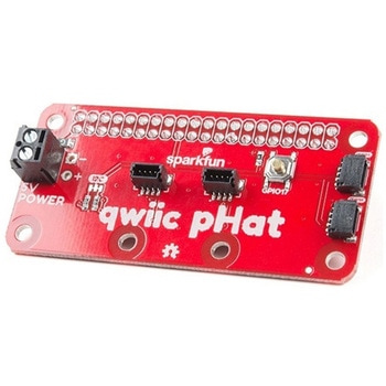
SPARKFUN¥2,598税込¥2,8581個33日以内出荷。Description。The SparkFun Qwiic pHAT V2.0 for Raspberry Pi provides you with the quickest and easiest way to enter into SparkFun's Qwiic ecosystem while still using that Raspberry Pi that you've come to know and love. The Qwiic pHAT connects the I2C bus(GND, 3.3V, SDA, and SCL)on your Raspberry Pi to an array of Qwiic connectors on the HAT. Since the Qwiic system allows for daisy-chaining boards with different addresses, you can stack as many sensors as you'd like to create a tower of sensing power!。The Qwiic pHAT V2.0 has four Qwiic connect ports(two on its side and two vertical), all on the same I2C bus. We've also made sure to add a simple 5V screw terminal to power boards that may need more than 3.3V and a general-purpose button(with the option to shut down the Pi with a script). Also updated, the mounting holes found on the board are now spaced to accommodate the typical Qwiic board dimension of 1.0"×1.0". This HAT is compatible with any Raspberry Pi that utilizes the standard 2x20 GPIO header as well as the NVIDIA Jetson Nano and Google Coral.。Note。When placing a Raspberry Pi and the pHAT in an enclosure(like the Pi Tin), we noticed that the pHAT was not fully inserted in Pi's header pins. For a secure connection, you'll need to add a pair of 1x20 stackable headers to extend the pins to your cart.。The SparkFun Qwiic Connect System is an ecosystem of I2C sensors, actuators, shields and cables that make prototyping faster and less prone to error. All Qwiic-enabled boards use a common 1mm pitch, 4-pin JST connector. This reduces the amount of required PCB space, and polarized connections mean you can't hook it up wrong.。Get Started with the SparkFun Qwiic pHAT Guide。Features。4x Qwiic Connection Ports。1x 5V Tolerant Screw Terminal。1x General Purpose Button。HAT-compatible 40-pin Female Headerアズワン品番67-0422-97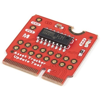
SparkFun MicroMod Update Tool
SPARKFUN¥1,798税込¥1,9781個33日以内出荷。Description。The SparkFun MicroMod Update Tool is built to interface with the MicroMod Asset Tracker Carrier Board and also makes it simple to communicate directly with the u-blox SARA-R510M8S module using u-blox's sophisticated m-center cellular evaluation software. If you're familiar with u-center, u-blox's GNSS evaluation software, you'll know how excellent their software is. m-center is every bit as good. Attach a USB-C cable and away you go!。The Update Tool is not a full MicroMod Processor Board, it is much simpler than that. It has a CH340C USB-Serial converter on it which gives you full access to all eight pins of the SARA-R5's UART interface via the Asset Tracker's USB-C connector. Think of it as a bridge from USB to serial.。The Update Tool features eight pairs of Plated Through Hole connections for the UART signals. You can use these to connect directly to the SARA UART using 3.3V signals if you want to. The split pads on the rear of the Tool can be opened to isolate the CH340C completely; the pins nearest the M.2 will link straight to the SARA UART.。Get Started with the MicroMod Update Tool Hookup Guide。Features。CH340C USB-Serial converter。Eight pairs of Plated Through Hole connections with split pad jumper links for:Serial Transmit(TX)。Serial Receive(RX)。Request To Send(RTS)。Clear To Send(CTS)。Data Terminal Ready(DTR)。Data Set Ready(DSR)。Ring Indicator(RI)。Data Carrier Detect(DCD)。LED indicator for:Power(3.3V)アズワン品番67-0423-52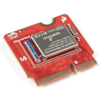
SparkFun MicroMod Artemis Processor
SPARKFUN¥6,198税込¥6,8181個33日以内出荷Description。Leveraging the ultra powerful Artemis Module, the SparkFun MicroMod Artemis Processor is the brain board of your dreams. With a Cortex-M4F with BLE 5.0 running up to 96MHz and with as low power as 6uA per MHz(less than 5mW), the M.2 MicroMod connector allows you to plug in a MicroMod Carrier Board with any number of peripherals. Let's have a look at what this processor board has to offer! If you need Machine Learning capabilities, Bluetooth, I2C functionality to connect to all our amazing Qwiic boards, and more the Artemis Processor is the perfect choice for your MicroMod Carrier Board.。At the heart of SparkFun's Artemis Module is Ambiq Micro's Apollo3 processor, whose ultra-efficient ARM Cortex-M4F processor is spec'd to run TensorFlow Lite using only 6uA/MHz. We've routed two I2C buses, eight GPIO, dedicated digital, analog, and PWM pins, multiple SPI as well as QuadSPI, and Bluetooth to boot. You really can't go wrong with this processor. Grab one today, pick up a compatible carrier board, and get hacking!。MicroMod is a modular interface ecosystem that connects a microcontroller "processor board" to various "carrier board" peripherals. Utilizing the M.2 standard, the MicroMod standard is designed to easily swap out processors on the fly. Pair a specialized carrier board for the project you need with your choice of compatible processor!。Get Started with the MicroMod Artemis Processor Guide。Features。Artemis General Features。1M Flash / 384k RAM。48MHz / 96MHz turbo available。6uA/MHz(operates less than 5mW at full operation)。48 GPIO - all interrupt capable。31 PWM channels。Built in BLE radio and antenna。10 ADC channels with 14-bit precision with up to 2.67 million samples per second effective continuous, multi-slot sampling rate。2 channel differential ADC。2 UARTs。6 I2C buses。6 SPI buses。2/4/8-bit SPI bus。PDM interface。I2S Interface。Secure 'Smart Card' interface。FCC/IC/CE Certified(ID Number 2ASW8-ART3MIS)。Specific Peripherals made available on MicroMod Artemis:1x USB dedicated for programming and debug。1x UART with flow control。2x I2C。1x SPI。1x Quad-SPI。8x Fast GPIO。2x Digital Pins。2x Analog Pins。2x PWM。1x Differential ADC pair。Status LED。VIN Level ADC。Additional peripherals are available but are shared on dedicated MicroMod pins.アズワン品番67-0423-05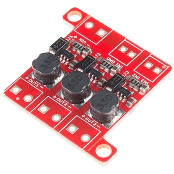
PicoBuck LED Driver
SPARKFUN¥5,298税込¥5,8281個33日以内出荷Description。The PicoBuck LED Driver is an economical and easy to use driver that will allow you to control and blend three different LEDs on three different channels. By default, each channel is driven at 330mA; that current can be reduced by either presenting an analog voltage or a PWM signal to the board. Version 12 of the board adds a solderable jumper that can be closed to increase the maximum current to 660mA. The new voltage regulator also increased the voltage rating on the various components on the board, allowing it to be used up to the full 36V rating of the AL8805 part.。Three signal inputs are provided for dimming control. You can use the PWM signal from an Arduino or your favorite microcontroller to dim each channel individually, or you can tie them all to the same PWM for simultaneous dimming. Dimming can be done by an analog voltage(20%-100% of max current by varying voltage from .5V-2.5V)or by PWM(so long as PWM minimum voltage is less than .4V and maximum voltage is more than 2.4V)for a full 0-100% range. A small jumper is provided for each channel to allow you to increase the drive strength from 330mA to 660mA. Two mounting holes for 4-40 or M3 screws are provided on either side of the board. They are perforated so they can be easily snapped off with a pair of pliers, if a smaller footprint is desired.。Note:。If you're going to use screw terminals, this board uses two different sizes. Check the related products for both sizes you'll need.。Note:。The PicoBuck LED Driver was made in collaboration with Ethan Zonca. A portion of each sale is given back to him.アズワン品番67-0420-83