カテゴリ
- 学童・教育用品(33)
- 制御機器(1)
絞り込み
ブランド
- SPARKFUN
- MIDAS(10)
- Seeed Studio(8)
- M5Stack(8)
- Canon(5)
- ビット・トレード・ワン(5)
- エコリカ(2)
- ワンダーキット(2)
- MICROCHIP(2)
- ASUS(エイスース)(1)
- POWERTIP(1)
- DIGILENT(1)
- FORDATA(1)
- MSI(エムエスアイ)(1)
- Electronic Assembly(1)
「i2c oled」の検索結果
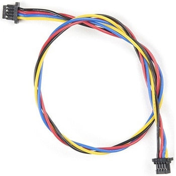 Flexible Qwiic Cable - 200mmSPARKFUN
¥689税込¥758
1個
33日以内出荷
DescriptionThis is a 200mm long 4-conductor cable with 1mm JST termination. It's designed to connect Qwiic enabled components together but can be used for other applications as well. The cable insulation is made from a highly malleable material making it more flexible than our original Qwiic cable particularly in tight spaces or enclosures.Each Qwiic Cable's wires have been color coded to red, black, blue and yellow.The SparkFun Qwiic connect system is an ecosystem of I2C sensors, actuators, shields and cables that make prototyping faster and less prone to error. All Qwiic-enabled boards use a common 1mm pitch, 4-pin JST connector. This reduces the amount of required PCB space, and polarized connections mean you can't hook it up wrong.FeaturesDimensions:200mm(7.87")Length
アズワン品番67-0426-04
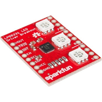 SparkFun LED Driver Breakout - LP55231SPARKFUN
¥3,500税込¥3,850
1個
5日以内出荷
DescriptionThe SparkFun LP55231 LED Driver Breakout is a self-contained solution for developing and deploying the nine-channel I2C LED controller. Remarkably simple, the breakout is equipped primarily with just the LP55231 LED controller IC, plus thr
アズワン品番67-0419-94
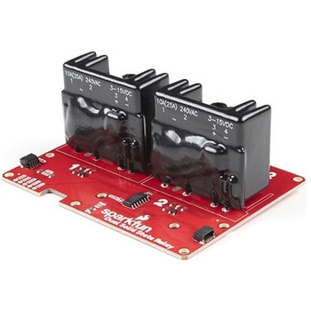 SparkFun Qwiic Dual Solid State RelaySPARKFUN
¥39,980税込¥43,978
1個
33日以内出荷
DescriptionThe SparkFun Qwiic Dual Solid State Relay is a power delivery board that allows users to switch two AC loads from a low power microcontroller using the SparkFun Qwiic connect system. The board features two 25A/250VAC solid state relays that utilize the Zero Cross Trigger method so you can toggle two loads on a 60Hz AC carrier signal on and off up to 120 times per second!An ATTiny84 acts as the "brain" of the SparkFun Qwiic Dual Solid Relay to accept I2C commands to toggle the two relays as well as a few other special commands. The I2C address of the ATtiny84A is software configurable so, if you have a seriously big power project in mind, you could daisy chain over 100 Qwiic Dual Solid State Relays.Messing with such high voltage is dangerous! We've included many safety precautions onto the PCB including ground isolation between the relay and other circuitry and a milled out area isolating each side of AC. However, with all the safety precautions included with the SparkFun Qwiic Dual Solid State Relay, this is still a power accessory for users who are experienced around, and knowledgeable about high AC voltage. If you're not comfortable with handling AC voltage in this way, you may want to check out the IoT Power Relay instead.Note:The relays are rated for a max of 25A with forced air cooling. If you do not have forced air cooling, 10A max through the relays is recommended.The SparkFun Qwiic connect system is an ecosystem of I2C sensors, actuators, shields and cables that make prototyping faster and less prone to error. All Qwiic-enabled boards use a common 1mm pitch, 4-pin JST connector. This reduces the amount of required PCB space, and polarized connections mean you can't hook it up wrong.Get Started with the SparkFun Qwiic Dual Solid State Relay GuideFeaturesOperating Voltage:2.5-3.6V(3.3V recommended)I2C Address:0x0A(Default)0x0B(Alternate via jumper select)Load Voltage Range:12-280VACMax Current(Through Relay):25A(240VAC with forced air cooling)Zero Cross TriggerNormally Open Circuit Only2x Qwiic Connector
アズワン品番67-0421-58
 SparkFun 6 Degrees of Freedom Breakout - LSM6DSO QwiicSPARKFUN
¥5,198税込¥5,718
1個
33日以内出荷
DescriptionThe SparkFun LSM6DSO 6 Degrees of Freedom Breakout is an accelerometer and gyroscope sensor with a giant 9kB FIFO buffer and embedded processing interrupt functions. Due to the capabilities and low cost of the LSM6DSO we've created this small breakout board just for you! Each LSM6DSO breakout has been designed to be super-flexible and can be configured specifically for many applications. With the LSM6DSO breakout you will be able to detect shocks, tilt, motion, taps, count steps, and even read the temperature!The LSM6DSO from STMicroelectronics is capable of reading accelerometer and gyroscope data up to 6.66kHz for more accurate movement sensing. As stated before this breakout also has the ability to buffer up to 9kB of data between reads, host other sensors, and drive interrupt pins all thanks to the LSM6DSO's built-in FIFO.Utilizing our handy Qwiic system, no soldering is required to connect it to the rest of your system. However, we still have broken out 0.1"-spaced pins in case you prefer to use a breadboard. Each pin has been broken out on the LSM6DSO, with one side of the board featuring power, I2C, and SPI functionality while the other side sporting pins that control auxiliary functionality and interrupt outputs. Please keep in mind that the LSM6DSO is a 3.3V device so supplying voltages greater than ~3.6V can permanently damage the IC. A logic level shifter is required for any development platform operating at 5V.The SparkFun Qwiic Connect System is an ecosystem of I2C sensors, actuators, shields and cables that make prototyping faster and less prone to error. All Qwiic-enabled boards use a common 1mm pitch, 4-pin JST connector. This reduces the amount of required PCB space, and polarized connections mean you can't hook it up wrong.Get Started With the SparkFun LSM6DSO Qwiic 6DoF GuideFeatures2x Qwiic connectorsI2C Address0x6B(default), 0x6AAccelerometer measurement range±2/±4/±8/±16 g full scaleGyro measurement range±125/±250/±500/±1000/±2000 dps full scaleEmbedded temperature sensor16-bit resolutionOperating voltage range1.71V to 3.6VTypically3.3Vif using the Qwiic cablePower consumption @ 1.8V0.55 mA in combo high-performance mode0.265 mA in combo low-power mode"Always on" experience with low power consumption for both accelerometer and gyroscopeI2C/SPI serial interface with main processor data synchronization featureSmart FIFO up to 9 kbyte based on features setOperating temperature range-40℃ to +85℃
アズワン品番67-0427-54
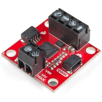 SparkFun Qwiic Motor DriverSPARKFUN
¥6,698税込¥7,368
1個
33日以内出荷
DescriptionThe SparkFun Qwiic Motor Driver takes all the great features of the Serial Controlled Motor Driver(SCMD)and miniaturizes them, adding Qwiic ports for plug and play functionality. Boasting the same 4245 PSOC and 2-channel motor ports as the SCMD, the SparkFun Qwiic Motor Driver is designed to communicate over I2C to make setting up your next robotic project as fast and easy as possible! Utilizing our handy Qwiic system and screw terminals for motor and power hook-up, no soldering is required to connect it to the rest of your system.With 1.2A steady state drive per channel(1.5A peak)and 127 levels of DC drive strength, this little Qwiic board is perfect for your small DC motor driver needs. Since the Qwiic Motor Driver is a 3.3V logic device, you'll need to use a logic level converter to interface to 5V.The I2C address of the Qwiic Motor Driver is 0x5D and is jumper selectable to 0x58, 0x59, 0x5A, 0x5B, ... 0x63.The SparkFun Qwiic Connect System is an ecosystem of I2C sensors, actuators, shields and cables that make prototyping faster and less prone to error. All Qwiic-enabled boards use a common 1mm pitch, 4-pin JST connector. This reduces the amount of required PCB space, and polarized connections mean you can't hook it up wrong.Need a custom board? This component can be found in SparkFun's A La Carte board builder. You can have a custom design fabricated with this component - and your choice of hundreds of other sensors, actuators and wireless devices - delivered to you in just a few weeks.Get Started With the Qwiic Motor Driver Hookup GuideFeatures1.5 A peak drive per channel, 1.2 A steady stateOperates from 3 to 11 Volts with 12V absolute max3.3V default VCC and logic127 levels of DC drive strength.Controllable by I2C or TTL UART signalsDirection inversion on a per motor basisGlobal Drive enableExposed small heat sink shapeSeveral I2C addresses, default UART bauds availableAdjustable I2C Address:0x5D Default2x Qwiic ConnectorsDocumentsSchematicEagle FilesBoard DimensionsHookup GuideArduino LibraryPython ModuleGithub Hardware Repo
アズワン品番67-0426-33
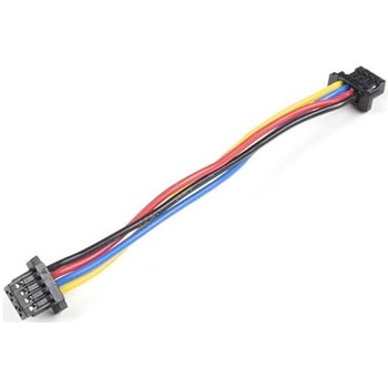 Flexible Qwiic Cable - 50mmSPARKFUN
¥469税込¥516
1個
33日以内出荷
DescriptionThis is a 50mm long 4-conductor cable with 1mm JST termination. It's designed to connect Qwiic enabled components together but can be used for other applications as well. The cable insulation is made from a highly malleable material making it more flexible than our original Qwiic cable particularly in tight spaces or enclosures.Each Qwiic Cable's wires have been color coded to red, black, blue and yellow.The SparkFun Qwiic connect system is an ecosystem of I2C sensors, actuators, shields and cables that make prototyping faster and less prone to error. All Qwiic-enabled boards use a common 1mm pitch, 4-pin JST connector. This reduces the amount of required PCB space, and polarized connections mean you can't hook it up wrong.FeaturesDimensions:50mm(1.96")Length
アズワン品番67-0426-06
 SparkFun Qwiic AdapterSPARKFUN
¥479税込¥527
1個
33日以内出荷
DescriptionThe SparkFun Qwiic Adapter provides the perfect means to make any old I2C board into a Qwiic-enabled board. This adapter breaks out the I2C pins from the Qwiic connectors to pins that you can easily solder with your favorite I2C-enabled device.The Qwiic Adapter has two Qwiic connection ports, all on the same I2C bus. Four plated through holes are broken out for SCL, SDA, 3.3V and GND. These pins can be used to convert an old I2C-enabled device into a Qwiic-enabled board.The SparkFun Qwiic Connect System is an ecosystem of I2C sensors, actuators, shields and cables that make prototyping faster and less prone to error. All Qwiic-enabled boards use a common 1mm pitch, 4-pin JST connector. This reduces the amount of required PCB space, and polarized connections mean you can't hook it up wrong.Get Started with the SparkFun Qwiic Adapter GuideFeatures2x Qwiic Connection PortsBroken-out I2C Pins
アズワン品番67-0419-69
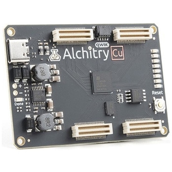 Alchitry Cu FPGA Development Board Lattice iCE40 HXSPARKFUN
¥15,980税込¥17,578
1個
33日以内出荷
DescriptionIf you are not needing a lot of power to start your FPGA adventure, or are looking for a more economical option, the Alchitry Cu FPGA Development Board might be the perfect option for you! The Alchitry Cu is a "lighter" FPGA version than the Alchitry Au but still offers something completely unique. FPGAs, or Field-Programmable Gate Arrays, are an advanced development board type for engineers and hobbyists alike to experience the next step in programming with electronics. The Cu truly exemplifies the trend of more affordable and increasingly powerful FPGA boards arriving each year. This board is a fantastic starting point into the world of FPGAs and the heart of your next project. Finally, now that this board is built by SparkFun, we added a Qwiic connector for easy I2C integration!The Alchitry Cu uses the Lattice iCE40 HX FPGA with 7680 logic cells and is supported by the open source tool chain Project IceStorm. The Cu possesses 79 IO pins with eight general purpose LEDs; a 100MHz on-board clock that can be manipulated internally by the FPGA; a USB-C connector to configure and power the board; and a USB to serial interface for data transfer.By adding stackable expansion boards similar to shields or HATs called "Elements," the Alchitry Cu is able to expand its own hardware capabilities by adding prototyping spaces, buttons, LEDs, and more!The SparkFun Qwiic Connect System is an ecosystem of I2C sensors, actuators, shields and cables that make prototyping faster and less prone to error. All Qwiic-enabled boards use a common 1mm pitch, 4-pin JST connector. This reduces the amount of required PCB space, and polarized connections mean you can't hook it up wrong.Get Started with our Learning FPGA TutorialsFeaturesLattice iCE40-HX8K FPGA - 7680 logic elements79 IO pins(3.3V logic level)USB-C to configure and power the boardEight general purpose LEDsOne button(typically used as a reset)100MHz on-board clock(can be multiplied internally by the FPGA)Powered with 5V through USB-C port, 0.1" holes, or headersUSB to serial interface for data transfer(up to 12Mbaud)Qwiic ConnectorDimensions of 65mm×45mmExamplesFirst FPGA Project - Getting Fancy with PWMExternal IO and Metastability
アズワン品番67-0423-08
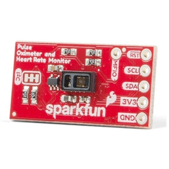 SparkFun Pulse Oximeter and Heart Rate Sensor - MAX30101 & MAX32664 QwiicSPARKFUN
¥13,980税込¥15,378
1個
33日以内出荷
DescriptionThe SparkFun Pulse Oximeter and Heart Rate Sensor is an I2C based biometric sensor, utilizing two chips from Maxim Integrated:the MAX32664 Biometric Sensor Hub and the MAX30101 Pulse Oximetry and Heart Rate Module. While the latter does all the sensing, the former is an incredibly small and fast Cortex M4 processor that handles all of the algorithmic calculations, digital filtering, pressure/position compensation, advanced R-wave detection, and automatic gain control. We've provided a Qwiic connector to easily connect to the I2C data lines but you will also need to connect to two additional lines. This board is very small, measuring at 1in×0.5in(25.4mm×12.7mm), which means it will fit nicely on your finger without all the bulk.The MAX30101 does all the sensing by utilizing its internal LEDs to bounce light off the arteries and arterioles in your finger's subcutaneous layer and sensing how much light is absorbed with its photodetectors. This is known as photoplethysmography. This data is passed onto and analyzed by the MAX32664 which applies its algorithms to determine heart rate and blood oxygen saturation(SpO2). SpO2 results are reported as the percentage of hemoglobin that is saturated with oxygen. It also provides useful information such as the sensor's confidence in its reporting as well as a handy finger detection data point. To get the most out of the sensor we've written an Arduino Library to make it easy to adjust all the possible configurations.The SparkFun Qwiic connect system is an ecosystem of I2C sensors, actuators, shields and cables that make prototyping faster and less prone to error. All Qwiic-enabled boards use a common 1mm pitch, 4-pin JST connector. This reduces the amount of required PCB space, and polarized connections mean you can't hook it up wrong.Get Started with the Pulse Oximeter and Heart Rate Monitor Hookup GuideFeaturesSparkFun Pulse Oximeter and Heart Rate SensorMAX30101 and MAX32664 sensor and sensor hubQwiic connectors for power and I2C interfaceI2C Address:0x55MAX30101 - Pulse Oximeter and Heart-Rate SensorHeart-Rate Monitor and Pulse Oximeter Sensor in LED Reflective SolutionIntegrated Cover Glass for Optimal, Robust PerformanceUltra-Low Power Operation for Mobile DevicesFast Data Output CapabilityRobust Motion Artifact ResilienceMAX32664 - Ultra-Low Power Biometric Sensor HubBiometric Sensor Hub SolutionFinger-Based Algorithms Measure Pulse Heart Rate and Pulse Blood Oxygenation Saturation(SpO2)Both Raw and processed data are availableBasic Peripheral mix optimizes size and performance
アズワン品番67-0426-96
 SparkFun Capacitive Touch Slider - CAP1203 QwiicSPARKFUN
¥2,498税込¥2,748
1個
33日以内出荷
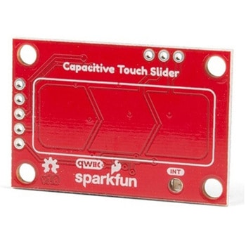
DescriptionDo you want to replace a slider or a button on your art project or science experiment with a more interesting interface? This Capacitive Touch Slider is a "Qwiic" and easy way to add capacitive touch to your next project. With the board's built in touch pads, you can immediately start playing with the touch capabilities as three unique touch inputs or as a slider. You can also enable a touch input to act as a power button, customize the sensitivity for your own touch pads, and play with the interrupt alert LED. Utilizing our Qwiic system, no soldering is required to connect it to the rest of your system. However, we have broken out 0.1"-spaced pins in case you prefer to use a breadboard or create your own touch pads.On the front of the board, there is an arrow shape which contains three separate capacitive touch pads. We also broke out the capacitive touch sensor lines as plated through-holes on the top of the board. You can use these pins to connect to your own capacitive touch pads. The CS1 pin connects to the left pad, the CS2 pin connects to the middle pad, and the CS3 pin connects to the right pad.NOTE:The I2C address of the CAP1203 is 0x28 and is hardware defined. A multiplexer/Mux is required to communicate to multiple CAP1203 sensors on a single bus. If you need to use more than one CAP1203 sensor consider using the Qwiic Mux Breakout.The SparkFun Qwiic connect system is an ecosystem of I2C sensors, actuators, shields and cables that make prototyping faster and less prone to error. All Qwiic-enabled boards use a common 1mm pitch, 4-pin JST connector. This reduces the amount of required PCB space, and polarized connections mean you can't hook it up wrong.Get Started with the SparkFun Capacitive Touch Slider GuideFeaturesCapacitive Touch3 unique capacitive touch inputsFeaturesEmulated sliderPower button settingProgrammable sensitivityAutomatic recalibrationI2C Address:0x28Qwiic EnabledOperating RangeSupply Voltage:3.3V - 5V
アズワン品番67-0427-06
 Flexible Qwiic Cable - 100mmSPARKFUN
¥659税込¥725
1個
33日以内出荷
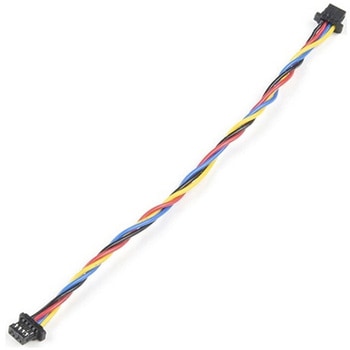
DescriptionThis is a 100mm long 4-conductor cable with 1mm JST termination. It's designed to connect Qwiic enabled components together but can be used for other applications as well. The cable insulation is made from a highly malleable material making it more flexible than our original Qwiic cable particularly in tight spaces or enclosures.Each Qwiic Cable's wires have been color coded to red, black, blue and yellow.The SparkFun Qwiic connect system is an ecosystem of I2C sensors, actuators, shields and cables that make prototyping faster and less prone to error. All Qwiic-enabled boards use a common 1mm pitch, 4-pin JST connector. This reduces the amount of required PCB space, and polarized connections mean you can't hook it up wrong.FeaturesDimensions:100mm(3.93")Length
アズワン品番67-0426-05
 BlinkM - I2C Controlled RGB LEDSPARKFUN
¥8,598税込¥9,458
1個
33日以内出荷
仕様●項目1:組込み(完成機能)●項目2:照光●項目4:LED+駆動回路アズワン品番67-0452-74
 SparkFun Qwiic Cable KitSPARKFUN
¥3,898税込¥4,288
1個
33日以内出荷
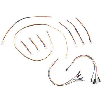
DescriptionThe SparkFun Qwiic Connect System is constantly growing in popularity with makers. So to make it even easier to get started, we've assembled this Qwiic Cable Kit for everyone. If you aren't sure which Qwiic cable to use, this handy box includes all of them allowing you to save a little money and time! It has a little something for everyone.The SparkFun Qwiic Cable Kit includes 10 cables of various lengths and styles that will get your Qwiic boards connected together, to a development platform, or to a breadboard. Each Qwiic Cable's wires have been color coded to red, black, blue and yellow with 1mm JST termination.The SparkFun Qwiic connect system is an ecosystem of I2C sensors, actuators, shields and cables that make prototyping faster and less prone to error. All Qwiic-enabled boards use a common 1mm pitch, 4-pin JST connector. This reduces the amount of required PCB space, and polarized connections mean you can't hook it up wrong.
アズワン品番67-0424-24
 SparkFun I2S Audio Breakout - MAX98357ASPARKFUN
¥1,998税込¥2,198
1個
33日以内出荷
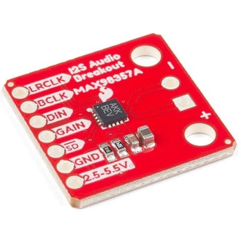
DescriptionThe SparkFun I2S Audio Breakout board uses the MAX98357A digital to analog converter(DAC), which converts I2S(not be confused with I2C)audio to an analog signal to drive speakers. The I2S Audio Breakout converts the digital audio signals using the I2S standard to an analog signal and amplifies the signal using a class D amplifier which can deliver up to 3.2W of power into a 4Ω load. The board can be configured to output only the left channel audio, right channel, or both.The SparkFun I2S Audio Breakout board is fairly simple, requiring only a few pin connections to get it up and working. By default the board is configured in "mono" operation, meaning the left and right signals are combined together to drive a single speaker. If you want a separate speaker for the left and right audio channels you'll need to cut the mono jumper. In addition to being able to select the audio channel output, the gain can also be configured in a few ways. The gain of the amplifier can be configured from as low as +3dB to as high as +15dB. While the channel selection can be configured on board, the gain however is controlled externally using the gain pin. By default, the board is configured for +9dB, but can be easily changed!Get Started with the SparkFun I2S Audio Breakout GuideFeaturesSupply Voltage Range:2.5V - 5.5V.Output Power:3.2W into 4Ω at 5V.Output Channel Selection:Left, Right, or Left/2 + Right/2(Default).Sample Rate:8kHz - 96kHz.Sample Resolution:16/32 bit.Quiescent Current:2.4mA.Filterless Class D OutputsNo MCLK RequiredClick and Pop ReductionShort-Circuit and Thermal Protection.
アズワン品番67-0422-64
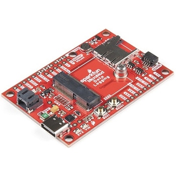 SparkFun MicroMod Data Logging Carrier BoardSPARKFUN
¥7,098税込¥7,808
1個
33日以内出荷
DescriptionThe SparkFun MicroMod Data Logging Board offers a highly customizable, low-power data logging platform using the MicroMod system allowing you to choose your own Processor to pair with the Carrier Board. The Data Logging Carrier Board breaks out connections for I2C via a Qwiic connector or standard 0.1"-spaced PTH pins along with SPI and serial UART connections for logging data from peripheral devices using those communication protocols.The Data Logging Carrier Board allows you to control power to both the Qwiic connector on the board and a dedicated 3.3V power rail for non-Qwiic peripherals so you can pick and choose when to power the peripherals you are monitoring the data from. It also features a charging circuit for single-cell Lithium-ion batteries along with a separate RTC battery-backup circuit to maintain power to a real-time clock circuit on your Processor Board.MicroMod is a modular interface ecosystem that connects a microcontroller "processor board" to various "carrier board" peripherals. Utilizing the M.2 standard, the MicroMod standard is designed to easily swap out processors on the fly. Pair a specialized carrier board for the project you need with your choice of compatible processor!Get Started with the MicroMod Data Logging Carrier Board GuideFeaturesM.2 MicroMod ConnectormicroSD socketUSB-C Connector3.3V 1A Voltage RegulatorQwiic ConnectorBoot/Reset ButtonsRTC Backup Battery Charge CircuitIndependent 3.3V regulators for Qwiic bus and peripheral add-onsControlled by digital pins on Processor Board to enable low power sleep modesPhillips #0 M2.5x3mm screw included
アズワン品番67-0423-16
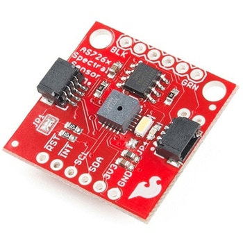 SparkFun Spectral Sensor Breakout - AS7263 NIR QwiicSPARKFUN
¥9,998税込¥10,998
1個
33日以内出荷
DescriptionThe SparkFun AS7263 Near Infrared(NIR)Spectral Sensor Breakout brings spectroscopy to the palm of your hand, making it easier than ever to measure and characterize how different materials absorb and reflect different wavelengths of light. The AS7263 Breakout is unique in its ability to communicate by both an I2C interface and serial interface using AT commands. Hookup is easy, thanks to the Qwiic connectors attached to the board --- simply plug one end of the Qwiic cable into the breakout and the other into one of the Qwiic shields, then stack the board on a development board. You'll be ready to upload a sketch to start taking spectroscopy measurements in no time.The AS7263 spectrometer detects wavelengths in the visible range at 610, 680, 730, 760, 810 and 860nm of light, each with 20nm of full-width half-max detection. The board also has multiple ways for you to illuminate objects that you will try to measure for a more accurate spectroscopy reading. There is an onboard LED that has been picked out specifically for this task, as well as two pins to solder your own LED into.Note:The I2C address of the AS7263 is 0x49 and is hardware defined. A multiplexer/Mux is required to communicate to multiple AS7263 sensors on a single bus. If you need to use more than one AS7263 sensor consider using the Qwiic Mux Breakout.The SparkFun Qwiic Connect System is an ecosystem of I2C sensors, actuators, shields and cables that make prototyping faster and less prone to error. All Qwiic-enabled boards use a common 1mm pitch, 4-pin JST connector. This reduces the amount of required PCB space, and polarized connections mean you can't hook it up wrong.Get Started with the SparkFun AS726X Spectral Sensor Breakout GuideFeatures6 near-IR channels:610nm, 680nm, 730nm, 760nm, 810nm and 860nm, each with 20nm FWHMNIR filter set realized by silicon interference filters16-bit ADC with digital accessProgrammable LED drivers2.7V to 3.6V with I2C interface2x Qwiic connectors
アズワン品番67-0426-70
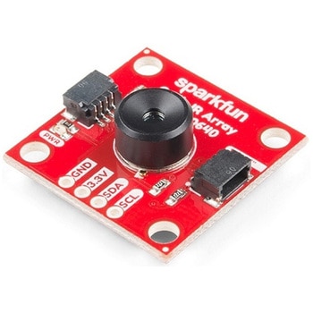 SparkFun IR Array Breakout - 110 Degree FOV, MLX90640 QwiicSPARKFUN
¥22,980税込¥25,278
1個
33日以内出荷
DescriptionIt's time to say hip hip array for this IR Breakout! The MLX90640 SparkFun IR Array Breakout is equipped with a 32x24 array of thermopile sensors creating, in essence, a low resolution thermal imaging camera. With this breakout you can detect surface temperatures from many feet away with an accuracy of ±1.5℃(best case). To make it even easier to get your low-resolution infrared image, all communication is enacted exclusively via I2C, utilizing our handy Qwiic system. However, we still have broken out 0.1"-spaced pins in case you prefer to use a breadboard.This specific IR Array Breakout features a 110°x75° field of view with a temperature measurement range of -40℃-300℃. The MLX90640 IR Array has pull up resistors attached to the I2C bus; both can be removed by cutting the traces on the corresponding jumpers on the back of the board. Please be aware that the MLX90640 requires complex calculations by the host platform so a regular Arduino Uno(or equivalent)doesn't have enough RAM or flash to complete the complex computations required to turn the raw pixel data into temperature data. You will need a microcontroller with 20,000 bytes or more of RAM. To achieve this, we recommend a Teensy 3.1 or above.Note:The I2C address of the MLX90640 is 0x33 and is hardware defined. A multiplexer/Mux is required to communicate to multiple MLX90640 sensors on a single bus. If you need to use more than one MLX90640 sensor consider using the Qwiic Mux Breakout.The SparkFun Qwiic connect system is an ecosystem of I2C sensors, actuators, shields and cables that make prototyping faster and less prone to error. All Qwiic-enabled boards use a common 1mm pitch, 4-pin JST connector. This reduces the amount of required PCB space, and polarized connections mean you can't hook it up wrong.Get Started with the SparkFun IR Array Breakout GuideFeaturesOperating Voltage:3V-3.6VCurrent Consumption:~18mAField of View:110°x75°Measurement Range:-40℃-300℃Resolution:±1.5℃Refresh Rate:0.5Hz-64HzI2C Address:0x332x Qwiic Connection Ports
アズワン品番67-0426-87
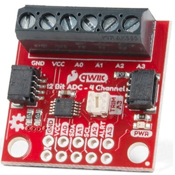 QWIIC 12BIT 4CHANNEL ADS1015SPARKFUN
¥5,498税込¥6,048
1個
33日以内出荷
DescriptionA lot of the time you just need to add more analog inputs to solve a problem. It happens. The SparkFun Qwiic 12 Bit ADC can provide four channels of I2C controlled ADC input to your Qwiic enabled project. These channels can be used as single-ended inputs, or in pairs for differential inputs. What makes this even more powerful is that it has a programmable gain amplifier that lets you "zoom in" on a very small change in analog voltage(but will still effect your input range and resolution). Utilizing our handy Qwiic system, no soldering is required to connect it to the rest of your system. However, we still have broken out 0.1"-spaced pins in case you prefer to use a breadboard.The ADS1015 uses its own internal voltage reference for measurements, but a ground and 3.3V reference are also available on the pin outs for users. This ADC board includes screw pin terminals on the four channels of input, allowing for solderless connection to voltage sources in your setup. It also has an address jumper that lets you choose one of four unique addresses(0x48, 0x49, 0x4A, 0x4B). With this, you can connect up to four of these on the same I2C bus and have sixteen channels of ADC. The maximum resolution of the converter is 12-bits in differential mode and 11-bits for single-ended inputs. Step sizes range from 125μV per count to 3mV per count depending on the full-scale range(FSR)setting.We have included an onboard 10K trimpot connected to channel A3. This is handy for initial setup testing and can be used as a simple variable input to your project. But don't worry, we added an isolation jumper so you can use channel A3 however you'd like.Note:The I2C address of the ADS1015 is 0x48 and is jumper selectable to 0x49, 0x4A, 0x4B. A multiplexer/Mux is required to communicate to multiple ADS1015 sensors on a single bus. If you need to use more than one ADS1015 sensor consider using the Qwiic Mux Breakout.The SparkFun Qwiic connect system is an ecosystem of I2C sensors, actuators, shields and cables that make prototyping faster and less prone to error. All Qwiic-enabled boards use a common 1mm pitch, 4-pin JST connector. This reduces the amount of required PCB space, and polarized connections mean you can't hook it up wrong.Get Started with the SparkFun Qwiic 12-Bit ADC Hookup GuideFeaturesADS1015Operating Voltage(VDD):2.0V-5.5V(Note:When powering with a Qwiic cable, the input range is only 3.3v)Operating Temperature:-40℃ to 125℃Operation Modes:Single-Shot, Continuous-Conversion(Default), and Duty CyclingAnalog Inputs:Measurement Type:Single-Ended(Default)Input Voltage Range:GND to VDDFull Scale Range(FSR):±.256V to ±6.114V(Default:2.048V)Resolution:12-bit(Differential)or 11-bit(Single-Ended)LSB size:0.125mV - 3mV(Default:1 mV)Sample Rate:128 Hz to 3.3 kHz(Default:1600SPS)Current Consumption(Typical):150μA-200μAI2C Address:0x48(Default), 0x49, 0x4A, or 0x4BScrew pin terminals for solderless connection to voltage sourcesFour unique I2C addresses:0x480x490x4A0x4B2x Qwiic connection portsOnboard 10K trimpot
アズワン品番67-0360-13
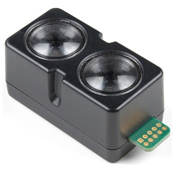 Garmin LIDAR-Lite v4 LED - Distance Measurement SensorSPARKFUN
¥22,980税込¥25,278
1個
33日以内出荷
DescriptionThe LIDAR-Lite v4 LED sensor is the next step in the LIDAR-Lite line. A small, lightweight, low-power optical ranging sensor. It's the first to incorporate ANT profile wireless networking technology into an optical sensor. Its built-in nRF52840 processor means that developers can create custom applications, or be operated as a stand-alone device right out of the box by using the preloaded stock application.Like the LIDAR-Lite v3 and LIDAR-Lite v3HP sensors; it can also be directly connected to an external micro-controller running a custom user application. As such, it provides a highly adaptable option for OEM and maker applications in robotics, Internet of Things, and unmanned vehicles ― or any application where an ultrasonic sensor might otherwise be used. It's perfect as the basic building block for applications where wireless capabilities, small size, light weight, low power consumption and high performance are important factors in a short-range, 10-meter, optical distance measuring sensor.The LIDAR-Lite v4 requires an external 5VDC power source and soldering is required. This Time-of-Flight ranging module uses a LED and optics for ranging. It does not use a laser; therefore, it is inherently eye-safe under normal usage.FeaturesResolution:1 cmMeasurement repeatability:As measured indoors to a 90% reflective target1 cm is equivalent to 1 standard deviationUsing "high accuracy" mode, with averaging:+/- 1 cm to 2 meters+/- 2 cm to 4 meters+/- 5 cm to 10 metersRange:5 cm to 10 meters(as measured from back of unit)Update rate:I2C = >200 Hz typicalANT(R)= up to 200 Hz to a 90% target indoors at 2m in normal operating modeInterface:I2C or ANT; user configurable for SPI using the Nordic SDKPower(operating voltage):4.75 - 5.25 VDCCurrent consumption:2mA idle, 85mA during acquisitionOperating temperature:-20 to 60° CLED wavelength:940 nmBeam divergence:4.77°Optical aperture:14.9 mmUnit size(HxWxD):2.1"×0.8"×0.9"(52.2×21.2×24.0 mm)Weight:14.6 g(0.5 oz)
アズワン品番67-0427-09
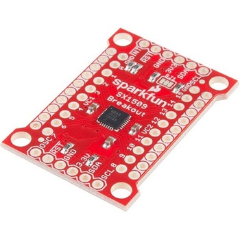 SparkFun 16 Output I/O Expander Breakout - SX1509SPARKFUN
¥2,198税込¥2,418
1個
33日以内出荷
DescriptionAre you low on I/O? No problem! The SX1509 Breakout is 16-channel GPIO expander with an I2C interface that means with just two wires, your microcontroller can interface with 16 fully configurable digital input/output pins. But the SX1509 can do so much more than just simple digital pin control. It can produce PWM signals, so you can dim LEDs. It can be set to blink or even breathe pins at varying rates. This breakout is similar to multiplexer or "mux," in that it allows you to get more IO from less pins. And, with built-in keypad engine, it can interface with up to 64 buttons set up in an 8x8 matrix.Two headers at the top and bottom of the breakout board function as the input and control headers to the board. This is where you can supply power to the SX1509, and where your I2C signals SDA and SCL will terminate. GPIO and power buses are broken out in every-which direction, and configurable jumpers cover most of the rest of the board.Since the I/O banks can operate between 1.2V and 3.6V(5.5V tolerant)independent of both the core and each other, this device can also work as level-shifter. The SX1509 breakout makes it easy to prototype so you can add more I/O onto your Arduino or I/O limited controller. We've even spun up an Arduino Library to get you started!FeaturesEnable Direct Level Shifting Between I/O Banks and Host Controller5.5V Tolerant I/Os, Up to 15mA Output Sink on All I/OsIntegrated LED Driver with Intensity ControlOn-Chip Keypad Scanning Engine Supports Up to 8x8 Matrix(64 Keys)16 Channels of True Bi-directional Style I/O400kHz I2C Compatible Slave Interface
アズワン品番67-0419-88
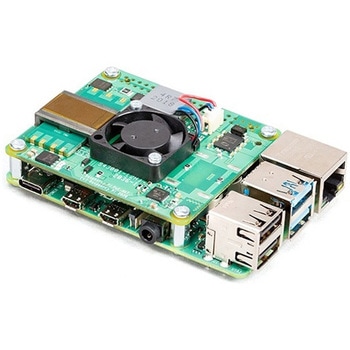 Raspberry Pi PoE+ HATSPARKFUN
¥12,980税込¥14,278
1個
33日以内出荷
DescriptionThe Raspberry Pi PoE+ HAT is designed to replace the existing Raspberry Pi PoE HAT in all new and existing designs. Like the original, the PoE+ HAT allows you to power your Raspberry Pi using Power over Ethernet networks. The PoE+ HAT meets all the requirements of the IEEE 802.3af(802.3at Type 1, PoE+)specifications. This ups the power the network can supply from 15.4 watts(PoE)to 25.5 Watts(PoE+)over CAT5 cable.No modification to the main Raspberry Pi board is needed for the PoE+ HAT to work but you will need to ensure that your Pi's software is up to date for all functionality to be available. The Raspberry Pi PoE+ HAT is fitted with a small fan that is controlled by the Raspberry Pi via I2C and will turn on and off automatically depending on the temperature of the main processor on your Pi.Note:There is no Raspberry Pi included with this product. Your desired Pi will need to be purchased separately.FeaturesInput voltage:37-57V DC, Class 2 deviceOutput power:5V DC/3.0ACooling:25mm×25mm brushless fan delivering 2.2CFM forprocessor coolingFully isolated switch-mode power supplyFan controlMechanically compatible with the existing Raspberry Pi PoE HAT
アズワン品番67-0423-62
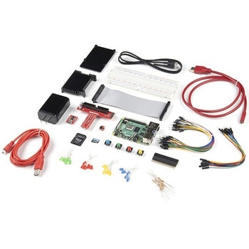 SparkFun Raspberry Pi 4 Hardware Starter Kit - 4GBSPARKFUN
¥56,980税込¥62,678
1個
33日以内出荷
DescriptionThe Raspberry Pi 4 Hardware Starter Kit provides a solid set of parts and instruction for working with the Raspberry Pi 4 in a more hardware-centric manner. While the Raspberry Pi isn't typically considered a go-to for hardware projects, its I/O pins hold a lot of benefits that you can use for a variety of applications. This kit covers the basics like using LEDs, and Buttons while providing a solid set of parts for working with any other hardware I/O and the 40-pin header. In addition, we've included all the parts needed for getting the Raspberry Pi 4 up and running whether it's on its own, or using a monitor(not included). The new 64GB MicroSD cards keep read/write commands running super fast, too.Most of the contents of the kit rely on the use of the 2x20, 40-pin header, so we've included a special extender to allow you to plug in the ribbon cable while using the provided heatsink case. We've also included a Qwiic Shim for easily working with I2C based Qwiic boards with the Pi. No soldering is required for this kit!Note:This variation includes the 4GB RAM option for the Raspberry Pi 4.Get Started with the Raspberry Pi 4 Model B Guide
アズワン品番67-0424-46
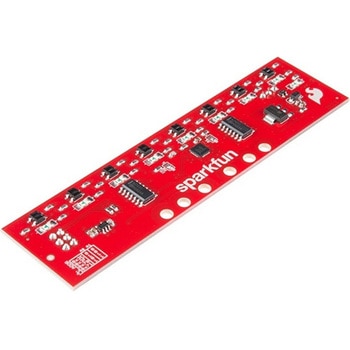 SparkFun Line Follower ArraySPARKFUN
¥13,980税込¥15,378
1個
33日以内出荷
DescriptionThe SparkFun Line Follower Array is a long board consisting of eight IR sensors that have been configured to read as digital bits! We have designed the SparkFun Line Follower Arrays to follow a dark line of about 3/4 inch width or smaller(spray paint or electrical tape)on a light background. Each array features visible LEDs that point upward when the board is attached(properly)so you can see what the robot sees, brightness control right on the board, and an I2C interface for reading and power control. Here at SparkFun, the RedBot Shadow Chassis was used as a test platform but really this was designed as an add-on for almost any bot.The line follower functions by taking an 8-bit reading of reflectance for use with following lines or reading dark/light patterns and can see from about 1/4 to 3/4 inches away. The IR brightness control and indicator can be adjusted with the on-board potentiometer and is capable of showing you the strength of the IR LEDs. Illumination can be turned on and off with software to conserve power, or left on all the time for faster readings. The SparkFun Line Follower Array requires 5V of power with a supply current range of 25-185mA with strobing disabled and 16-160mA with it enabled. Additionally we have added six mounting holes to the line follower with the two inner holes designed to fit our Shadow Chassis while the other four are general purpose.Note:As you know our Sun emits quite a bit of infrared light, making the SparkFun Line Follower Array much less effective in direct sunlight. Plan your projects accordingly!Features8 sensor eyes(QRE1113, like in our line sensor breakout)I2C interfaceAdjust IR brightness on the fly with a knobSwitch IR on and off with softwareSwitch visual indicators on and off with softwareInvert dark/light sight with softwareBased on the SX1509 I/O expander
アズワン品番67-0426-55
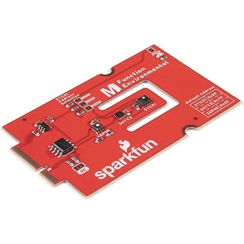 SparkFun MicroMod Environmental Function BoardSPARKFUN
¥44,980税込¥49,478
1個
33日以内出荷
DescriptionThe SparkFun MicroMod Environmental Function Board adds additional sensing options to the MicroMod Processor Boards. This Function Board includes three sensors to monitor air quality(SGP40), humidity temperature(SHTC3), and CO2 concentrations(STC31)in your indoor environment. To make it even easier to use, all communication is over the MicroMod's I2C bus!The SGP40 measures the quality of the air in your room or house. The SGP40 uses a metal oxide(MOx)sensor with a temperature controlled micro hotplate and provides a humidity-compensated volatile organic compound(VOC)based indoor air quality signal. Both the sensing element and VOC Algorithm feature an unmatched robustness against contaminating gases present in real world applications enabling a unique long term stability as well as low drift and device to device variation.The SHTC3 is a highly accurate digital humidity and temperature sensor. The SHTC3 uses a capacitive humidity sensor with a relative humidity measurement range of 0 to 100% RH and bandgap temperature sensor with a temperature measurement range of -40℃ to 125℃. The SHTC3 builds on the success of their SHTC1 sensor with higher accuracy(±2% RH, ±0.2℃)than its predecessor, enabling greater flexibility.The STC31 measures CO2 concentrations based on thermal conductivity and has two CO2 measurement ranges:0 to 25 vol%; and 0 to 100 vol%. The measurement repeatability is 0.2 vol%, with a stability of 0.025 vol% / ℃. The measurement accuracy depends on the measurement range:0.5 vol% + 3% measured value; 1 vol% + 3% measured value. Using measurements from the SHTC3, the STC31 is able to provide humidity-compensated measurements together with improved temperature compensation. The STC31 can compensate for atmospheric pressure too - which is handy if, like us, you're up in the mountains!The outstanding performance of these three sensors is based on Sensirion's patented CMOSens(R)technology, which combines the sensor element, signal processing, and digital calibration on a small CMOS chip. The well-proven CMOS technology is perfectly suited for high-quality mass production and is the ideal choice for demanding and cost-sensitive OEM applications.Utilizing our handy M.2 MicroMod connector, no soldering is required to connect it to your system. Simply match up the key on your processor and function board's beveled edge connector to their respective key on the M.2 connector, then secure them to the main board with screws. The MicroMod Environmental Function Board can then be read via the I2C port. The board is equipped with the AP2112 3.3V voltage regulator, I2C pull-up resistors, power LED, jumper to disable the LED, and jumpers for alternative STC31 addresses.Note:A MicroMod Processor and Main Board are not included with this MicroMod Environmental Function Board. These boards will need to be purchased separately.MicroMod is a modular interface ecosystem that connects a microcontroller "processor board" to various "carrier board" peripherals. Utilizing the M.2 standard, the MicroMod standard is designed to easily swap out processors and function boards on the fly. Pair a specialized carrier board for the project you need with your choice of compatible processor!Get Started with the MicroMod Environmental Function BoardFeaturesInput voltage range2.5V to 6.0VTyp.5Vvia Main Board's USB connectorTyp.~3.7V to 4.2Vvia Main Board's LiPo battery ConnectorI/O voltage3.3VAP2112 3.3V voltage regulator(rated 600mA)Power LEDI2C pull-up resistorsSensirion SGP40 Air Quality SensorUses I2C interfaceAddress:0x59(default)Operating voltage range1.7V to 3.6V(Typ.3.3V)Operating temperature range-20℃ to +55℃Typical current consumption2.6mAduring continuous operation(at 3.3V)34μAwhen idle(heater off)Output signalDigital raw value(SRAW):0 - 65535 ticksDigital processed value(VOC Index):0 - 500 VOC index pointsSwitch-on behaviorTime until reliably detecting VOC events:<60sTime until specifications are met:<1hRecommended sampling intervalVOC Index:1sSRAW:0.5s - 10s(Typ. 1s)Sensirion SHTC3 Humidity and Temperature SensorUses I2C interfaceAddress:0x70(default, non-configurable)Operating voltage range1.62V - 3.6V(Typ.3.3V)Operating temperature range-40℃ to +125 ℃Relative HumidityMeasurement range:0% to 100%Typical accuracy:±2 %RHResolution:0.01 %RHTemperatureMeasurement range:-40℃ to +125 ℃Typical accuracy:±0.2 ℃Resolution:0.01 ℃Typical current consumption(varies based on mode)4.9μA to 430μA(Normal Mode)0.5μA to 270μA(Low Power Mode)Allows the STC31 to compensate for humidity and temperatureSensirion STC31 CO2 SensorUses I2C interfaceAddresses:0x29(default), 0x2A, 0x2B, 0x2COperating voltage range2.7V to 5.5V(Typ.3.3V)Operating temperature range-20 ℃ to +85 ℃Calibrated for CO2 in N2 and CO2 in airMeasurement ranges0 to 25 vol% in N20 to 100 vol% in airAccuracy0.5 vol% + 3% measured value in N21 vol% + 3% measured value in airConcentration and temperature resolution:16-bitRepeatability:0.2 vol%Temperature stability:0.025 vol% / ℃Start-up time:14 msThermal conductivity sensor provides calibrated gas concentration and temperature outputJumpersPWR LEDI2C pull-up resistorsSTC31 address selectionNote:The I2C addresses that are reserved for each sensor is 0x59(SGP40), 0x70(SHTC3), 0x29(STC31). A multiplexer/Mux is required to communicate to multiple SHTC3 sensors on a single bus. The SHTC3 uses the same address as the Qwiic Mux(0x70). For advanced users that are using multiple SHTC3's with the Qwiic Mux, you will need to adjust the Qwiic Mux's default address.
アズワン品番67-0427-60
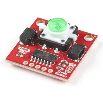 SparkFun Qwiic Button - Green LEDSPARKFUN
¥1,698税込¥1,868
1個
33日以内出荷
DescriptionButtons are an easy and tactile way to interface with your project, but why would you want to deal with debouncing, polling, and wiring up pull-up resistors? The Qwiic Button with built-in green LED simplifies all of those nasty worries away into an easy to use I2C device! Utilizing our Qwiic Connect System, using the button is as simple as connecting cable and loading up some pre-written code!If you need multiple buttons for your project, fear not! Each button has configurable I2C address, so you can daisy-chain multiple buttons over Qwiic and still address each one individually. We've got an example in our Arduino library that provides super-easy way to configure your Qwiic Button to whatever I2C address you desire. You can download the library through the Arduino library manager by searching 'SparkFun Qwiic Button' or you can get the GitHub repo as .zip file and install the library from there.In addition to handling blinking and debouncing, the Qwiic Button has configurable interrupts that can be configured to activate upon button press or click. We've also taken the liberty of implementing FIFO queue onboard the Qwiic Button where it keeps an internal record of when the button was pressed. This means that code on your microcontroller need not waste valuable processing time checking the status of the button but instead can run small function whenever the button is pressed or clicked! For more information on interrupts check out our guide here!The SparkFun Qwiic Connect System is an ecosystem of I2C sensors, actuators, shields and cables that make prototyping faster and less prone to error. All Qwiic-enabled boards use common 1mm pitch, 4-pin JST connector. This reduces the amount of required PCB space, and polarized connections mean you can't hook it up wrong.Get Started with the SparkFun Qwiic Button GuideFeatures12mm Green LED Button rated for 50mABuilt in LED can be configured for your desired level of blinkiness!Each button has configurable I2C addressConfigurable interrupts check out our guide here!FIFO queueDon't like the color green? Check out the SparkFun Qwiic Button Breakout and add another colored button!Red LED Tactile ButtonBlue LED Tactile ButtonGreen LED Tactile ButtonWhite LED Tactile Button
アズワン品番67-0420-14
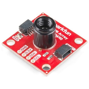 SparkFun IR Array Breakout - 55 Degree FOV, MLX90640 QwiicSPARKFUN
¥22,980税込¥25,278
1個
33日以内出荷
DescriptionIt's time to say hip hip array for this IR Breakout! The MLX90640 SparkFun IR Array Breakout is equipped with a 32x24 array of thermopile sensors creating, in essence, a low resolution thermal imaging camera. With this breakout you can detect surface temperatures from many feet away with an accuracy of ±1.5℃(best case). To make it even easier to get your infrared image, all communication is enacted exclusively via I2C, utilizing our handy Qwiic system. However, we still have broken out 0.1"-spaced pins in case you prefer to use a breadboard.This specific IR Array Breakout features a55°x35°field of view with a temperature measurement range of -40℃-300℃. The MLX90640 IR Array has pull up resistors attached to the I2C bus; both can be removed by cutting the traces on the corresponding jumpers on the back of the board. Please be aware that the MLX90640 requires complex calculations by the host platform so a regular Arduino Uno(or equivalent)doesn't have enough RAM or flash to complete the complex computations required to turn the raw pixel data into temperature data. You will need a microcontroller with 20,000 bytes or more of RAM. To achieve this, we recommend a Teensy 3.1 or above.The SparkFun Qwiic connect system is an ecosystem of I2C sensors, actuators, shields and cables that make prototyping faster and less prone to error. All Qwiic-enabled boards use a common 1mm pitch, 4-pin JST connector. This reduces the amount of required PCB space, and polarized connections mean you can't hook it up wrong.Get Started with the SparkFun IR Array Breakout GuideFeaturesOperating Voltage:3V-3.6VCurrent Consumption:~18mAField of View:55°x35°Measurement Range:-40℃-300℃Resolution:±1.5℃Refresh Rate:0.5Hz-64HzI2C Address:0x332x Qwiic Connection Ports
アズワン品番67-0426-88
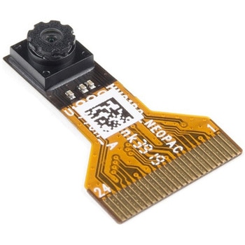 Himax CMOS Imaging Camera - HM01B0SPARKFUN
¥3,698税込¥4,068
1個
33日以内出荷
DescriptionThe HM01B0 from Himax Imaging is an ultra low power CMOS Monochrome Image Sensor that enables the integration of an "Always On" camera for computer vision applications such as gestures, intelligent ambient light and proximity sensing, tracking and object identification. The sensor allows the sensor to consume very low power of <2mW at QVGA 30FPS. This low power consumption and vision applications camera comes with a ribbon cable that mates to the camera connector populated on the following products:MicroMod Machine Learning Carrier BoardArtemis Development KitEdge Development Board - Apollo3 BlueThe HM01B0 contains 320×320 pixel resolution and supports a 320×240 window mode which can be readout at a maximum frame rate of 60FPS, and a 2×2 monochrome binning mode with a maximum frame rate of 120FPS. The video data is transferred over a configurable 1bit, 4bit or 8bit interface with support for frame and line synchronization. The sensor integrates black level calibration circuit, automatic exposure and gain control loop, self-oscillator and motion detection circuit with interrupt output to reduce host computation and commands to the sensor to optimize the system power consumption.FeaturesImage SensorUltra Low Power Image Sensor(ULPIS)designed for Always On vision devices and applicationsHigh sensitivity 3.6μ BrightSenseTM pixel technology320×320 active pixel resolution with support for QVGA window, vertical flip and horizontal mirror readoutProgrammable black level calibration target, frame size, frame rate, exposure, analog gain(up to 8x)and digital gain(up to 4x)Automatic exposure and gain control loop with support for 50 / 60Hz flicker avoidanceFlexible 1bit, 4bit and 8bit video data interface with video frame and line syncMotion Detection circuit with programmable ROI and detection threshold with digital output to serve as an interruptOn-chip self oscillatorI2C 2-wire serial interface for register accessHigh CRA for low profile module designSensor ParametersActive Pixel Array 320×320Pixel Size 3.6 μm×3.6 μmFull Image Area 1152 μm×1152 μmDiagonal(Optical Format)1.63 mm(1/11″)Scan Mode:ProgressiveShutter Type:Electronic Rolling ShutterFrame Rate MAX 51 fps @ 320×320, 60 fps @ 320×240(QVGA)CRA(maximum)30℃Sensor SpecificationsSupply Voltage:Analog - 2.8 V, Digital - 1.5V(Internal LDO:1.5V - 2.8V), I/O - 1.5 - 2.8VInput Reference Clock:3 - 50 MHzSerial Interface(I2C):2-wire, 400 KHz max.Video Data Interface:1b, 4b, 8b with frame / line SYNCOutput Clock Rate MAX:50 MHz for 1bit, 12.5 MHz for 4bit, 6.25 MHz for 8bitEst. Power Consumption(include IO with 5pF load):QVGA 60FPS(Typical)<4 mWQVGA 30FPS(Typical)<2 mW
アズワン品番67-0427-08
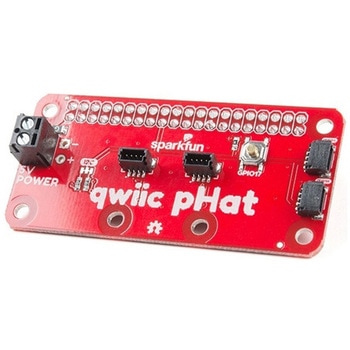 SparkFun Qwiic pHAT v2.0 for Raspberry PiSPARKFUN
¥2,598税込¥2,858
1個
33日以内出荷
DescriptionThe SparkFun Qwiic pHAT V2.0 for Raspberry Pi provides you with the quickest and easiest way to enter into SparkFun's Qwiic ecosystem while still using that Raspberry Pi that you've come to know and love. The Qwiic pHAT connects the I2C bus(GND, 3.3V, SDA, and SCL)on your Raspberry Pi to an array of Qwiic connectors on the HAT. Since the Qwiic system allows for daisy-chaining boards with different addresses, you can stack as many sensors as you'd like to create a tower of sensing power!The Qwiic pHAT V2.0 has four Qwiic connect ports(two on its side and two vertical), all on the same I2C bus. We've also made sure to add a simple 5V screw terminal to power boards that may need more than 3.3V and a general-purpose button(with the option to shut down the Pi with a script). Also updated, the mounting holes found on the board are now spaced to accommodate the typical Qwiic board dimension of 1.0"×1.0". This HAT is compatible with any Raspberry Pi that utilizes the standard 2x20 GPIO header as well as the NVIDIA Jetson Nano and Google Coral.NoteWhen placing a Raspberry Pi and the pHAT in an enclosure(like the Pi Tin), we noticed that the pHAT was not fully inserted in Pi's header pins. For a secure connection, you'll need to add a pair of 1x20 stackable headers to extend the pins to your cart.The SparkFun Qwiic Connect System is an ecosystem of I2C sensors, actuators, shields and cables that make prototyping faster and less prone to error. All Qwiic-enabled boards use a common 1mm pitch, 4-pin JST connector. This reduces the amount of required PCB space, and polarized connections mean you can't hook it up wrong.Get Started with the SparkFun Qwiic pHAT GuideFeatures4x Qwiic Connection Ports1x 5V Tolerant Screw Terminal1x General Purpose ButtonHAT-compatible 40-pin Female Header
アズワン品番67-0422-97
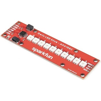 SparkFun Qwiic LED Stick - APA102CSPARKFUN
¥3,500税込¥3,850
1個
33日以内出荷
DescriptionThe SparkFun Qwiic LED Stick features ten addressable APA102 LEDs, making it easy to add full color LED control using I2C. Write to individual LEDs to display a count in binary, or write to the whole strip for cool lighting effects. You can even add more LEDs to the end if you need to. We've written an Arduino library and Python package that take care of the I2C and communication to the LEDs so all you have to do is decide what color each LED should be.The LED Stick has a default I2C address of 0x23 but can be changed with a simple command, allowing you to control up to 100 LEDs(10 Qwiic LED Sticks)on a single bus! The address can also be changed to 0x22 by closing the solder jumper on the back of the board.This board is one of our many Qwiic compatible boards! Simply plug and go. No soldering, no figuring out which is SDA or SCL, and no voltage regulation or translation required!Warning:Using a lot of LEDs can draw a lot of current. Make sure to consider the power limits of your setup. If you expect your LED chain to draw more than 600mA of current, connect your external supply directly to VLED. Closing the jumper from VLED to VCC will add a 4.7uF decoupling capacitor.The SparkFun Qwiic Connect System is an ecosystem of I2C sensors, actuators, shields and cables that make prototyping faster and less prone to error. All Qwiic-enabled boards use a common 1mm pitch, 4-pin JST connector. This reduces the amount of required PCB space, and polarized connections mean you can't hook it up wrong.Get Started with the Qwiic LED Stick GuideFeatures10x APA102C addressable LEDs driven by an ATTiny85Default I2C Address:0x23(Adjustable to 0x22 via Jumper)2x Qwiic Connectors
アズワン品番67-0421-83
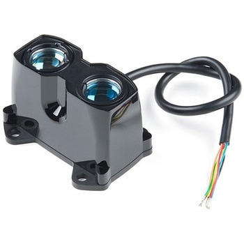 LIDAR-Lite v3HPSPARKFUN
¥49,980税込¥54,978
1個
33日以内出荷
DescriptionLIDAR has never looked so good! This is the LIDAR-Lite v3HP, a compact, high-performance optical distance measurement sensor from Garmin(TM). The LIDAR-Lite v3HP istheideal optical ranging solution for drone, robot, or unmanned vehicle applications. Each sensor is housed in a durable, IPX7-rated housing and includes all the core features and user configurability of the popular LIDAR-Lite v3.The v3HP is very similar in function to that of the v3 but it can now sample faster at rates greater than 1kHz(where as the v3 is only capable of up to 500Hz). Another improvement is that this v3HP model is more power efficient with current consumption rates 40mA less than the v3(that's 65mA as opposed to 105mA while idle, and 85mA instead of 130mA while acquiring).Each LIDAR-Lite v3HP has a range of 1m to 40m and features an edge-emitting, 905nm(1.3 watts), single-stripe laser transmitter, 8m Radian beam divergence, and an optical aperture of 12.5mm. This version of the LIDAR-Lite still operates at 5VDC(6V max)with a peak power of 1.3W and still possesses an accuracy of +/- 2.5cm at >2m. On top of everything else, the LIDAR-Lite is user-configurable, allowing adjustment between accuracy, operating range and measurement time and can be interfaced via I2C or PWM with the attached 200mm cable.Note:CLASS 1 LASER PRODUCT CLASSIFIED EN/IEC 60825-1 2014. This product is in conformity with performance standards for laser products under 21 CFR 1040, except with respect to those characteristics authorized by Variance Number FDA-2016-V-2943 effective September 27, 2016.Get Started with the LIDAR-Lite v3HP GuideFeaturesResolution:1 cmTypical accuracy:+/- 2.5cm at distances greater than 2 meters(Refer to operating manual for complete operating specifications)Range:1m to 40mUpdate rate:Greater than 1kHzInterface:I2C or PWMPower(operating voltage):4.75-5VDC; 6V MaxCurrent consumption:65ma idle; 85ma during acquisitionOperating temperature:-20℃ to 60℃Laser wave length/Peak power:905nm/1.3WBeam divergence:8m RadianOptical aperture:12.5mmWater rating:IPX7Unit dimensions:24.5mm×53.5mm×33.5mm(1.0in×2.1in×1.3in)Weight:34g(1.2oz)
アズワン品番67-0426-76
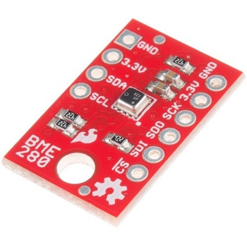 SparkFun Atmospheric Sensor Breakout - BME280SPARKFUN
¥7,498税込¥8,248
1個
33日以内出荷
DescriptionThe SparkFun BME280 Atmospheric Sensor Breakout is the easy way to measure barometric pressure, humidity, and temperature readings all without taking up too much space. Basically, anything you need to know about atmospheric conditions you can find out from this tiny breakout. The BME280 Breakout has been design to be used in indoor/outdoor navigation, weather forecasting, home automation, and even personal health and wellness monitoring.The on-board BME280 sensor measures atmospheric pressure from 30kPa to 110kPa as well as relative humidity and temperature. The breakout provides a 3.3V SPI interface, a 5V tolerant I2C interface(with pull-up resistors to 3.3V), takes measurements at less than 1mA and idles less than 5μA. The BME280 Breakout board has 10 pins, but no more than six are used at a single time. The left side of the board provide power, ground, and I2C pins. The remaining pins which provide SPI functionality and have another power and ground, are broken out on the other side.Note:The breakout does NOT have headers installed and will need to purchased and soldered on yourself. Check theRecommended Productssection below for the type of headers we use in the Hookup Guide!FeaturesOperation Voltage:3.3VI2C SPI Communications InterfaceTemp Range:-40C to 85CHumidity Range:0 - 100% RH, =-3% from 20-80%Pressure Range:30,000Pa to 110,000Pa, relative accuracy of 12Pa, absolute accuracy of 100PaAltitude Range:0 to 30,000 ft(9.2 km), relative accuracy of 3.3 ft(1 m)at sea level, 6.6(2 m)at 30,000 ft.Incredibly Small
アズワン品番67-0426-57
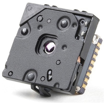 FLIR Lepton 2.5 - Thermal Imaging ModuleSPARKFUN
¥68,980税込¥75,878
1個
33日以内出荷
DescriptionThe FLIR Lepton(R)2.5 - Thermal Imaging Module is a radiometric-capable long wave infrared(LWIR)camera solution that is smaller than a dime, fits inside a smartphone, and is less expensive than traditional IR cameras. With a focal plane array of 80x60 active pixels, this Lepton easily integrates into native mobile-devices and other electronics as an IR sensor or thermal image sensor. The radiometric Lepton captures accurate, calibrated, and non-contact temperature data in every pixel.For large quantities:We currently have a limit of one per customer order on the FLIR Lepton 2.5 module due to supply chain issues as a result of COVID-19. If you need to place a distributor order please contact your sales rep and they will assist you. For bulk order for this module please visit our Volume Pricing Page for inquiries of stock. At this time, we cannot guarantee orders for this module but we will do what we can to work with you in fulfilling your request.FeaturesEffective Frame Rate:8.6 Hz(commercial application exportable)Input Clock:25-MHz nominal, CMOS IO Voltage LevelsOutput Format:User-selectable 14-bit, 8-bit(AGC applied), or 24-bit RGB(AGC and colorization applied)Pixel Size:17 μmRadiometric Accuracy:High gain:Greater of +/- 5℃ or 5%(typical)Low gain:Greater of +/- 10℃ or 10%(typical)Scene Dynamic Range:-10-140 ℃(high gain); up to 450℃(low gain)typicalSpectral Range:Longwave infrared, 8 μm to 14 μmTemperature Compensation:Automatic. Output image independent of camera temperature.Thermal Sensitivity:<50 mK(0.050° C)Video Data Interface:Video over SPIControl Port:CCI(I2C-like), CMOS IO Voltage LevelsPackage Dimensions - Socket Version(w×l×h):11.8×12.7×7.2 mmMechanical Interface:32-pin socket interface to standard Molex(R)socketNon-Operating Temperature Range:-40 ℃ to +80 ℃Optimum Temperature Range:-10℃ to +80℃Shock:1500 G @ 0.4 msArray format:80×60, progressive scanFOV - Diagonal:63.5°FOV - Horizontal:50°(nominal)Image Optimization:Factory configured and fully automatedNon-Uniformity Correction(NUC):Automatic with shutterSensor Technology:Uncooled VOx microbolometerSolar protection:IntegralInput Supply Voltage:2.8 V, 1.2 V, 2.5 V to 3.1 V IOPower Dissipation:150 mW(operating), 650 mW(during shutter event), 4 mW(standby)
アズワン品番67-0427-21
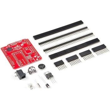 Teensy Arduino Shield AdapterSPARKFUN
¥4,798税込¥5,278
1個
33日以内出荷
DescriptionThe Teensy is an amazing and compact development platform in breadboard friendly form factor, but what if you could incorporate it into the Arduino architecture? The Teensy Arduino Shield Adapter allows you to attach your Teensy and utilize your favorite Arduino shields without the requirement of breadboard or any complicated wiring. Needless to say, the Teensy Arduino Shield Adapter is useful tool for upgrading all of your existing Arduino projects to more powerful controller!As we stated before, the Teensy Arduino Shield Adapter provides basic Arduino compatibility with your run-of-the-mill shield but there are few other fun features that we've added on, as well. These features include Real Time Clock(RTC)battery, JST battery connector, 4-12V barrel jack connector, an ICSP header, and more. Because this board is simply an adapter, there is no special programming required to start working with the adapter. You will, however, need to program the Teensy for any Arduino shield you'd like to work with.While the adapter design can fit the Teensy LC footprint, it has been designed to fully utilize the features of the Teensy 3.1. Not all of the features available on the adapter are compatible with the LC so please be sure to check the Hookup Guide in theDocumentssection below to ensure functionality for your project. Please keep in mind that this adapter may be incompatible with some 5V Arduino shields. Please check our hookup guide for more information.Note:The Teensy Arduino Shield Adapter comes as kit and will need to be soldered together.Note:Due to the requirements of shipping the batteries in this kit, orders may take longer to process and therefore do not qualify for same-day shipping. Additionally, these batteries can not be shipped via Ground or Economy methods to Alaska or Hawaii. Sorry for any inconvenience this may cause.FeaturesArduino R3 InterfaceReal Time Clock BatteryJST Battery ConnectorBarrel JackI2C JumpersICSP HeaderDAC Pin Header
アズワン品番67-0424-36
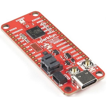 SparkFun Thing Plus - RP2040SPARKFUN
¥6,698税込¥7,368
1個
33日以内出荷
DescriptionThe SparkFun Thing Plus - RP2040 is a low-cost, high performance board with flexible digital interfaces featuring the Raspberry Pi Foundation's RP2040 microcontroller. Besides the Thing Plus orFeatherfootprint(with 18 GPIO pins), the board also includes an SD card slot, 16MB(128Mbit)flash memory, a JST single cell battery connector(with a charging circuit and fuel gauge sensor), an addressable WS2812 RGB LED, JTAG PTH pins, four(4-40 screw)mounting holes, and our signature Qwiic connector.The RP2040 contains two ARM Cortex-M0+ processors(up to 133MHz)and features:264kB of embedded SRAM in six banks6 dedicated IO for SPI Flash(supporting XIP)30 multifunction GPIO:Dedicated hardware for commonly used peripheralsProgrammable IO for extended peripheral supportFour 12-bit ADC channels with internal temperature sensor(up to 0.5 MSa/s)USB 1.1 Host/Device functionalityThe RP2040 is supported with both C/C++ and MicroPython cross-platform development environments, including easy access to runtime debugging. It has UF2 boot and floating-point routines baked into the chip. While the chip has a large amount of internal RAM, the board includes an additional 16MB of external QSPI flash memory to store program code.The SparkFun Qwiic Connect System is an ecosystem of I2C sensors, actuators, shields and cables that make prototyping faster and less prone to error. All Qwiic-enabled boards use a common 1mm pitch, 4-pin JST connector. This reduces the amount of required PCB space, and polarized connections mean you can't hook it up wrong.Get Started With the Thing Plus RP2040 Hookup GuideFeaturesSparkFun Thing Plus - RP2040 FeaturesRaspberry Pi Foundation's RP2040 microcontroller16MB QSPI Flash MemoryJTAG PTH PinsThing Plus(or Feather)Form-Factor:18[1]x Multifunctional GPIO Pins[2]Four available 12-bit ADC channels with internal temperature sensor(500kSa/s)Up to eight 2-channel PWMUp to two UARTsUp to two I2C busesUp to two SPI busesUSB-C Connector:USB 1.1 Host/Device functionality2-pin JST Connector for a LiPo Battery(not included)500mA charging circuitQwiic ConnectorButtons:BootResetLEDs:PWR- Red 3.3V power indicatorCHG- Yellow battery charging indicator25- Blue status/test LED(GPIO 25)WS2812- Addressable RGB LED(GPIO 08)Four Mounting Holes:4-40 screw compatibleDimensions:2.3"×0.9"RP2040 General FeaturesDual Cortex M0+ processors, up to 133 MHz264 kB of embedded SRAM in 6 banks6 dedicated IO for QSPI flash, supporting execute in place(XIP)30 programmable IO for extended peripheral supportSWD interfaceTimer with 4 alarmsReal time counter(RTC)USB 1.1 Host/Device functionalitySupported programming languagesMicroPythonC/C++1.Note:GPIO 08is not included in this count, as it passes through the WS2812 addressable RGB LED first.GPIO 07andGPIO 23are counted as a single GPIO because they are tied together.2.Note:The GPIO pins are programmable so you can reconfigure the pins! Check out the RP2040 datasheet for more information on the GPIO functionality.
アズワン品番67-0423-56