カテゴリ
- 学童・教育用品(26)
絞り込み
ブランド
- SPARKFUN
- Igus(イグス)(672)
- CRANK BROTHERS(28)
- GATOR Case(3)
- LUMILEDS(1)
- MICROCHIP(1)
- MOXA(1)
- NSK(日本精工)(7)
- OSG(オーエスジー)(9)
- SICK(2)
- SKF(日本エスケイエフ)(1)
- まつうら工業(1)
- サンライズ(2)
- セキスイ(25)
- テラモト(1)
- フエニックス・コンタクト(1)
- ホンダ(3)
- 永岡書店(3)
- 積水成型工業(2)
- ブランドをもっと見る
「igus」の検索結果
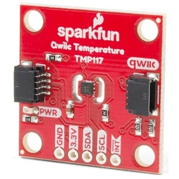
SparkFun High Precision Temperature Sensor - TMP117 Qwiic
SPARKFUN¥4,898税込¥5,3881個26日以内出荷。Description。The SparkFun Qwiic TMP117 breakout is a high precision temperature sensor equipped with an I2C interface. It outputs temperature readings with high precision of ±0.1℃ across the temperature range of -20℃ to +50℃s with no calibration and a maximum range from -55℃ to 150℃. The SparkFun High Precision Temperature Sensor also has a very low power consumption rate which minimizes the impact of self-heating on measurement accuracy. Utilizing our handy Qwiic system, no soldering is required to connect it to the rest of your system. However, we still have broken out 0.1"-spaced pins in case you prefer to use a breadboard.。The SparkFun High Precision Temperature Sensor also includes programmable temperature limits, and digital offset for system correction. While the TMP102 is capable of reading temperatures to a resolution of 0.0625℃ and is accurate up to 0.5℃, the on-board TMP117 is not only more precise but has a 16-bit resolution of 0.0078℃!。To make this breakout even easier to use, we've written an Arduino library to help you get started "Qwiic-ly." Check the Documents tab above for more information.。The SparkFun Qwiic Connect System is an ecosystem of I2C sensors, actuators, shields and cables that make prototyping faster and less prone to error. All Qwiic-enabled boards use a common 1mm pitch, 4-pin JST connector. This reduces the amount of required PCB space, and polarized connections mean you can't hook it up wrong.。The TMP117 High Precision Temperature Sensor can also be automatically detected, scanned, configured, and logged using the OpenLog Artemis datalogger system. No programming, soldering, or setup required!。Need a custom board? This component can be found in SparkFun's A La Carte board builder. You can have a custom design fabricated with this component - and your choice of hundreds of other sensors, actuators and wireless devices - delivered to you in just a few weeks.。Get Started with the SparkFun High Precision TMP117 Hookup Guide。Features。Uses I2C interface(Qwiic-enabled)。Four selectable addresses。0x48(default), 0x49, 0x4A, 0x4B。16-bit resolution, 0.0078℃。High accuracy, digital temperature sensor。±0.1℃(max)from ?20℃ to 50℃。±0.15℃(max)from ?40℃ to 70℃。±0.2℃(max)from ?40℃ to 100℃。±0.25℃(max)from ?55℃ to 125℃。±0.3℃(max)from ?55℃ to 150℃。Operating temperature range。-55℃ to +150℃。Operating voltage range。1.8V to 5.5V。Typically 3.3V if using the Qwiic cable。Low power consumption。3.5μA(1-Hz conversion cycle)。150nA(shutdown current)。Programmable operating modes。Continuous, one-shot, and shutdown。Programmable temperature alert limits。Selectable averaging for reduced noise。Digital offset for system correction。NIST traceability。。Documents。Schematic。Eagle Files。Board Dimensions。Hookup Guide。Datasheet(TMP117)。Arduino Library。GitHub Hardware Repoアズワン品番67-0427-10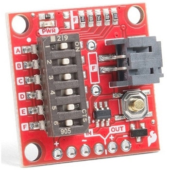
SparkFun Nano Power Timer - TPL5110
SPARKFUN¥2,398税込¥2,6381個30日以内出荷。Description。Sometimes we want our projects on, but sometimes we want to turn them off for a while to save power. The SparkFun Nano Power Timer will run while only consuming minimal power(approximately 35nA)and turn your project on after a set amount of time. When you are done polling your sensors, posting data to the web, writing to your logger, or planning world domination, your microcontroller can tell the Nano Power Timer to turn off the power. No more running your microcontroller all day when you only want to read the ambient temperature once per hour.。The TPL5110 delay is configured with the use of resistors. We've added a six-way DIP switch to select one of the five preinstalled resistors. The sixth switch is attached to a pad to add your own PTH(or SMD)resistor. The delays associated with the preinstalled headers are shown on the bottom of the board for quick setup. Additionally, you can select more than one switch to combine the resistors in parallel(up to 26 options not including the custom resistor), check out the hookup guide for a nice chart as to the total resistance and corresponding delay for each combination.。The Nano Power Timer can handle voltages between 1.8V and 5.5V as well as current up to 1.1A with times from 100ms to two hours(preconfigured settings range from 30s to 2h). You will find a button on the board which will allow you a quick override to the delay so you can turn your project on whenever you like.。Get Started with the SparkFun Nano Power Switch。Features。Supply Voltage:1.8V to 5.5V。Current consumption at 2.5V:35nA Typical(50nA Max)。Selectable Time intervals:100ms to 7200s(2 hours)。Timer Accuracy:1%アズワン品番67-0425-68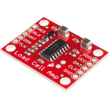
LOAD CELL AMP HX711
SPARKFUN¥3,500税込¥3,8501個33日以内出荷。Description。The SparkFun Load Cell Amplifier is a small breakout board for the HX711 IC that allows you to easily read load cells to measure weight. By connecting the amplifier to your microcontroller you will be able to read the changes in the resistance of the load cell, and with some calibration you'll be able to get very accurate weight measurements. This can be handy for creating your own industrial scale, process control or simple presence detection.。This version of the SparkFun Load Cell Amplifier features a few changes that you specifically asked for! We have separated the analog and digital supply, as well as added a 3.3uH inductor and a 0.1uF filter capacitor for digital supply. Need even more? Checkout the SparkFun Qwiic Scale. It has all the features of the HX711 but with additional library support, a true I2C interface, and no soldering required!。The HX711 uses a two-wire interface(Clock and Data)for communication. Any microcontroller's GPIO pins should work, and numerous libraries have been written, making it easy to read data from the HX711. Check the hookup guide below for more information.。Load cells use a four-wire Wheatstone bridge configuration to connect to the HX711. These are commonly colored RED, BLK, WHT, GRN and YLW. Each color corresponds to the conventional color coding of load cells:Red(Excitation+ or VCC)。Black(Excitation- or GND)。White(Amplifier-, Signal- or Output-)。Green(A+, S+ or O+)。Yellow(Shield)。The YLW pin acts as an optional input that is not hooked up to the strain gauge but is utilized to ground and shield against outside EMI(electromagnetic interference). Please keep in mind that some load cells might have slight variations in color coding.。Note:Special thanks to Bodge for supplying the Library for the HX711!。Get Started with the HX711 Load Cell Amplifier Guide。Features。Operation Voltage:2.7V--5V。Operation Current:< 1.5mA。Selectable 10SPS or 80SPS output data rate。Simultaneous 50 and 60Hz supply rejectionアズワン品番67-0362-17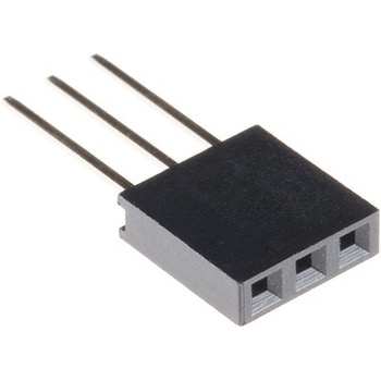
Stackable Header - 3 Pin Female, 0.1"
SPARKFUN¥349税込¥3841個33日以内出荷Description。This is a simple 3 pin female PTH header. This header is in a configuration that makes it ideal to be used with the MyoWare Muscle Sensor line. Each pin has a spacing of 0.1" in between each other.アズワン品番67-0425-26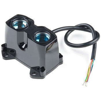
LIDAR-Lite v3HP
SPARKFUN¥52,980税込¥58,2781個33日以内出荷Description。LIDAR has never looked so good! This is the LIDAR-Lite v3HP, a compact, high-performance optical distance measurement sensor from Garmin(TM). The LIDAR-Lite v3HP is。the。ideal optical ranging solution for drone, robot, or unmanned vehicle applications. Each sensor is housed in a durable, IPX7-rated housing and includes all the core features and user configurability of the popular LIDAR-Lite v3.。The v3HP is very similar in function to that of the v3 but it can now sample faster at rates greater than 1kHz(where as the v3 is only capable of up to 500Hz). Another improvement is that this v3HP model is more power efficient with current consumption rates 40mA less than the v3(that's 65mA as opposed to 105mA while idle, and 85mA instead of 130mA while acquiring).。Each LIDAR-Lite v3HP has a range of 1m to 40m and features an edge-emitting, 905nm(1.3 watts), single-stripe laser transmitter, 8m Radian beam divergence, and an optical aperture of 12.5mm. This version of the LIDAR-Lite still operates at 5VDC(6V max)with a peak power of 1.3W and still possesses an accuracy of +/- 2.5cm at >2m. On top of everything else, the LIDAR-Lite is user-configurable, allowing adjustment between accuracy, operating range and measurement time and can be interfaced via I2C or PWM with the attached 200mm cable.。Note:CLASS 1 LASER PRODUCT CLASSIFIED EN/IEC 60825-1 2014. This product is in conformity with performance standards for laser products under 21 CFR 1040, except with respect to those characteristics authorized by Variance Number FDA-2016-V-2943 effective September 27, 2016.。Get Started with the LIDAR-Lite v3HP Guide。Features。Resolution:1 cm。Typical accuracy:+/- 2.5cm at distances greater than 2 meters(Refer to operating manual for complete operating specifications)。Range:1m to 40m。Update rate:Greater than 1kHz。Interface:I2C or PWM。Power(operating voltage):4.75-5VDC; 6V Max。Current consumption:65ma idle; 85ma during acquisition。Operating temperature:-20℃ to 60℃。Laser wave length/Peak power:905nm/1.3W。Beam divergence:8m Radian。Optical aperture:12.5mm。Water rating:IPX7。Unit dimensions:24.5mm×53.5mm×33.5mm(1.0in×2.1in×1.3in)。Weight:34g(1.2oz)アズワン品番67-0426-76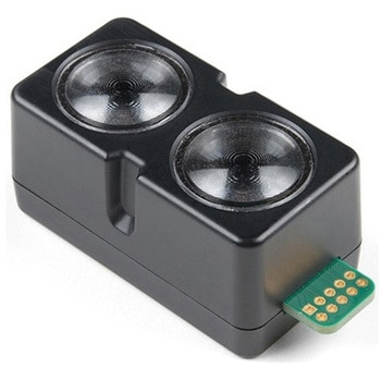
Garmin LIDAR-Lite v4 LED - Distance Measurement Sensor
SPARKFUN¥22,980税込¥25,2781個33日以内出荷Description。The LIDAR-Lite v4 LED sensor is the next step in the LIDAR-Lite line. A small, lightweight, low-power optical ranging sensor. It's the first to incorporate ANT profile wireless networking technology into an optical sensor. Its built-in nRF52840 processor means that developers can create custom applications, or be operated as a stand-alone device right out of the box by using the preloaded stock application.。Like the LIDAR-Lite v3 and LIDAR-Lite v3HP sensors; it can also be directly connected to an external micro-controller running a custom user application. As such, it provides a highly adaptable option for OEM and maker applications in robotics, Internet of Things, and unmanned vehicles ― or any application where an ultrasonic sensor might otherwise be used. It's perfect as the basic building block for applications where wireless capabilities, small size, light weight, low power consumption and high performance are important factors in a short-range, 10-meter, optical distance measuring sensor.。The LIDAR-Lite v4 requires an external 5VDC power source and soldering is required. This Time-of-Flight ranging module uses a LED and optics for ranging. It does not use a laser; therefore, it is inherently eye-safe under normal usage.。Features。Resolution:1 cm。Measurement repeatability:As measured indoors to a 90% reflective target。1 cm is equivalent to 1 standard deviation。Using "high accuracy" mode, with averaging:+/- 1 cm to 2 meters。+/- 2 cm to 4 meters。+/- 5 cm to 10 meters。Range:5 cm to 10 meters(as measured from back of unit)。Update rate:I2C = >200 Hz typical。ANT(R)= up to 200 Hz to a 90% target indoors at 2m in normal operating mode。Interface:I2C or ANT; user configurable for SPI using the Nordic SDK。Power(operating voltage):4.75 - 5.25 VDC。Current consumption:2mA idle, 85mA during acquisition。Operating temperature:-20 to 60° C。LED wavelength:940 nm。Beam divergence:4.77°。Optical aperture:14.9 mm。Unit size(HxWxD):2.1"×0.8"×0.9"(52.2×21.2×24.0 mm)。Weight:14.6 g(0.5 oz)アズワン品番67-0427-09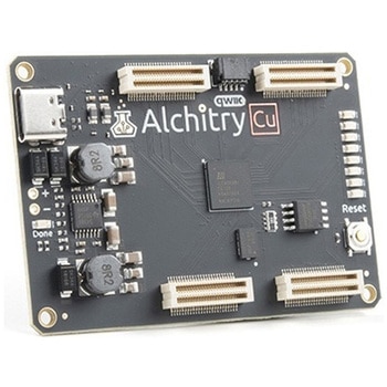
Alchitry Cu FPGA Development Board Lattice iCE40 HX
SPARKFUN¥15,980税込¥17,5781個33日以内出荷Description。If you are not needing a lot of power to start your FPGA adventure, or are looking for a more economical option, the Alchitry Cu FPGA Development Board might be the perfect option for you! The Alchitry Cu is a "lighter" FPGA version than the Alchitry Au but still offers something completely unique. FPGAs, or Field-Programmable Gate Arrays, are an advanced development board type for engineers and hobbyists alike to experience the next step in programming with electronics. The Cu truly exemplifies the trend of more affordable and increasingly powerful FPGA boards arriving each year. This board is a fantastic starting point into the world of FPGAs and the heart of your next project. Finally, now that this board is built by SparkFun, we added a Qwiic connector for easy I2C integration!。The Alchitry Cu uses the Lattice iCE40 HX FPGA with 7680 logic cells and is supported by the open source tool chain Project IceStorm. The Cu possesses 79 IO pins with eight general purpose LEDs; a 100MHz on-board clock that can be manipulated internally by the FPGA; a USB-C connector to configure and power the board; and a USB to serial interface for data transfer.。By adding stackable expansion boards similar to shields or HATs called "Elements," the Alchitry Cu is able to expand its own hardware capabilities by adding prototyping spaces, buttons, LEDs, and more!。The SparkFun Qwiic Connect System is an ecosystem of I2C sensors, actuators, shields and cables that make prototyping faster and less prone to error. All Qwiic-enabled boards use a common 1mm pitch, 4-pin JST connector. This reduces the amount of required PCB space, and polarized connections mean you can't hook it up wrong.。Get Started with our Learning FPGA Tutorials。Features。Lattice iCE40-HX8K FPGA - 7680 logic elements。79 IO pins(3.3V logic level)。USB-C to configure and power the board。Eight general purpose LEDs。One button(typically used as a reset)。100MHz on-board clock(can be multiplied internally by the FPGA)。Powered with 5V through USB-C port, 0.1" holes, or headers。USB to serial interface for data transfer(up to 12Mbaud)。Qwiic Connector。Dimensions of 65mm×45mm。。Examples。First FPGA Project - Getting Fancy with PWM。External IO and Metastabilityアズワン品番67-0423-08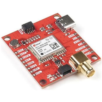
SparkFun GPS Breakout - NEO-M9N, SMA Qwiic
SPARKFUN¥22,980税込¥25,2781個33日以内出荷Description。The SparkFun NEO-M9N GPS Breakout is a high quality GPS board with equally impressive configuration options including SMA. The NEO-M9N module is a 92-channel u-blox M9 engine GNSS receiver, meaning it can receive signals from the GPS, GLONASS, Galileo, and BeiDou constellations with ~1.5 meter accuracy. This breakout supports concurrent reception of four GNSS. This maximizes position accuracy in challenging conditions increasing, precision and decreases lock time; and thanks to the onboard rechargeable battery, you'll have backup power enabling the GPS to get a hot lock within seconds! Additionally, this u-blox receiver supports I2C(u-blox calls this Display Data Channel)which makes it perfect for the Qwiic compatibility so we don't have to use up our precious UART ports. Utilizing our handy Qwiic system, no soldering is required to connect it to the rest of your system. However, we still have broken out 0.1"-spaced pins in case you prefer to use a breadboard.。The NEO-M9N module detects jamming and spoofing events and can report them to the host, so that the system can react to such events. A SAW(Surface Acoustic Wave)filter combined with an LNA(Low Noise Amplifier)in the RF path is integrated into the NEO-M9N module which allows normal operation even under strong RF interferences.。U-blox based GPS products are configurable using the popular, but dense, windows program called u-center. Plenty of different functions can be configured on the NEO-M9N:baud rates, update rates, geofencing, spoofing detection, external interrupts, SBAS/D-GPS, etc. All of this can be done within the SparkFun Arduino Library!。The SparkFun NEO-M9N GPS Breakout is also equipped with an on-board rechargeable battery that provides power to the RTC on the NEO-M9N. This reduces the time-to-first fix from a cold start(~24s)to a hot start(~2s). The battery will maintain RTC and GNSS orbit data without being connected to power for plenty of time.。This product requires an antenna:Be sure to check out the related products/hookup accessories and pick a suitable SMA antenna for your project.。The SparkFun Qwiic Connect System is an ecosystem of I2C sensors, actuators, shields and cables that make prototyping faster and less prone to error. All Qwiic-enabled boards use a common 1mm pitch, 4-pin JST connector. This reduces the amount of required PCB space, and polarized connections mean you can't hook it up wrong.。The NEO-M9N GPS Breakout can also be automatically detected, scanned, configured, and logged using the OpenLog Artemis datalogger system. No programming, soldering, or setup required!。Get Started With the SparkFun NEO-M9N GPS Guide。Features。Integrated SMA connector for use with antenna of your choice。92-Channel GNSS Receiver。1.5m Horizontal Accuracy。25Hz Max Update Rate(four concurrent GNSS)。Time-To-First-Fix:Cold:24s。Hot:2s。Max Altitude:80,000m。Max G:≦4。Max Velocity:500m/s。Velocity Accuracy:0.05m/s。Heading Accuracy:0.3 degrees。Time Pulse Accuracy:30ns。3.3V VCC and I/O。Current Consumption:~31mA Tracking GPS+GLONASS。Software Configurable。Geofencing。Odometer。Spoofing Detection。External Interrupt。Pin Control。Low Power Mode。Many others!。Supports NMEA, UBX, and RTCM protocols over UART or I2C interfacesアズワン品番67-0423-87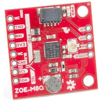
SparkFun GPS Breakout - ZOE-M8Q Qwiic
SPARKFUN¥14,980税込¥16,4781個33日以内出荷Description。The SparkFun ZOE-M8Q GPS Breakout is a high accuracy, miniaturized, GPS board that is perfect for applications that don't possess a lot of space. The on-board ZOE-M8Q is a 72-channel GNSS receiver, meaning it can receive signals from the GPS, GLONASS, BeiDou, and Galileo constellations. This increases precision and decreases lock time and thanks to the onboard rechargable battery you'll have backup power enabling the GPS to get a hot lock within seconds! Additionally, this u-blox receiver supports I2C(u-blox calls this Display Data Channel)which made it perfect for the Qwiic compatibility so we don't have to use up our precious UART ports. Utilizing our handy Qwiic system, no soldering is required to connect it to the rest of your system. However, we still have broken out 0.1"-spaced pins in case you prefer to use a breadboard.。U-blox based GPS products are configurable using the popular, but dense, windows program called u-center. Plenty of different functions can be configured on the ZOE-M8Q:baud rates, update rates, geofencing, spoofing detection, external interrupts, SBAS/D-GPS, etc. All of this can be done within the SparkFun Arduino Library. We've also made sure to configure the UART pin grouping on the breakout to an industry standard to insure that it easily connects to a Serial Basic.。The SparkFun ZOE-M8Q GPS Breakout is also equipped with an on-board rechargeable battery that provides power to the RTC on the ZOE-M8Q. This reduces the time-to-first fix from a cold start(~30s)to a hot start(~1s). The battery will maintain RTC and GNSS orbit data without being connected to power for up to five hours. Since the ZOE-M8Q is a tiny GPS receiver and to minimize its footprint, we've added a U.FL connector to allow the use of both large standard ceramic antennas as well as very small chip scale antennas.。Note:The I2C address of the ZOE-M8Q is 0x42 and is software configurable. A multiplexer/Mux is required to communicate to multiple ZOE-M8Q sensors on a single bus. If you need to use more than one ZOE-M8Q sensor consider using the Qwiic Mux Breakout.。The SparkFun Qwiic Connect System is an ecosystem of I2C sensors, actuators, shields and cables that make prototyping faster and less prone to error. All Qwiic-enabled boards use a common 1mm pitch, 4-pin JST connector. This reduces the amount of required PCB space, and polarized connections mean you can't hook it up wrong.。The ZOE-M8Q GPS Breakout can also be automatically detected, scanned, configured, and logged using the OpenLog Artemis datalogger system. No programming, soldering, or setup required!。Get Started With the SparkFun ZOE-M8Q Hookup Guide。Features。72-Channel GNSS Receiver。2.5m Horizontal Accuracy。18Hz Max Update Rate。Time-To-First-Fix:Cold:26s。Hot:1s。Max Altitude:50,000m。Max G:≦4。Max Velocity:500m/s。Velocity Accuracy:0.05m/s。Heading Accuracy:0.3 degrees。Time Pulse Accuracy:30ns。3.3V VCC and I/O。Current Consumption:~29mA Tracking GPS+GLONASS。Software Configurable。Geofencing。Odometer。Spoofing Detection。External Interrupt。Pin Control。Low Power Mode。Many others!。Supports NMEA, UBX, and RTCM protocols over UART or I2C interfacesアズワン品番67-0423-76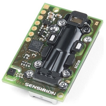
CO2 Humidity and Temperature Sensor - SCD30
SPARKFUN¥23,980税込¥26,3781個33日以内出荷Description。The SCD30 from Sensirion is a high quality Nondispersive Infrared(NDIR)based CO2 sensor capable of detecting 400 to 10000ppm with an accuracy of ±(30ppm+3%). In order to improve accuracy the SCD30 has temperature and humidity sensing built-in, as well as commands to set the current altitude. For additional accuracy the SCD30 also accepts ambient pressure readings!。We've written an Arduino library to make reading the CO2, humidity, and temperature very easy. It can be downloaded through the Arduino Library manager:search for 'SparkFun SCD30' or it can be found in the。Documents。tab above.。The SCD30 Humidity and Temperature Sensor can also be automatically detected, scanned, configured, and logged using the OpenLog Artemis datalogger system. No programming, soldering, or setup required!。Note:The SCD30 has an automatic self-calibration routine. Sensirion recommends 7 days of continuous readings with at least 1 hour a day of 'fresh air' for self-calibration to complete.。Features。Power supply voltage:3.3V - 5.5V。NDIR CO2 sensor technology。Integrated temperature and humidity sensor。Best performance-to-price ratio。Dual-channel detection for superior stability。Small form factor:35 mm×23 mm×7 mm。Measurement range:400 ppm - 10.000 ppm。Accuracy:±(30 ppm + 3%)。Current consumption:19 mA @ 1 meas. per 2 s.。Energy consumption:120 mJ @ 1 measurement。Fully calibrated and linearized。Digital interface UART or I2Cアズワン品番67-0430-35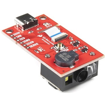
SparkFun 2D Barcode Scanner Breakout
SPARKFUN¥20,980税込¥23,0781個33日以内出荷。Description。The SparkFun 2D Barcode Scanner Breakout is a nifty little breakout board featuring the DE2120 barcode scanner module from DYScan. The DE2120 reads 20 different barcode symbologies(both 1D and 2D)using a camera coupled with on-board image processing to identify and decode everything from UPC codes to QR codes. The module also features two LEDs:one for illumination and one to project the red line that you're used to seeing from laser-based scanners.。This breakout board makes it easy to explore all of the capabilities of the DE2120 without dealing with finicky flat flex cables. The scanner's USB interface is exposed via the on-board USB-C connector. A buzzer and status LED are connected to the module through appropriate drive circuits and a push button tactile switch is provided on the "trigger" pin. When you're ready to incorporate the module into your embedded project, you can leverage the 5 pin header for direct access to the TTL serial pins, power pins, and trigger input.。The module can be configured either by using the serial interface or by scanning command barcodes found in the Settings Manual.。All keyboard, HID, and serial can be transmitted over the single USB-C connector. The DE2120 has the unique ability to enumerate all three protocols including a CDC serial driver so the device appears as a standard COM port.。Get Started with the 2D Barcode Scanner Breakout Hookup Guide。Features。USB-C Connector for USB HID Interface and Virtual COM port。Reads 20 different symbologies。1D Symbologies。UPC-A。UPC-E。EAN-8。EAN-13。Code 128。GS1-128。Code 39。Code 93。Code 11。Interleaved 2-of-5。Matrix 2-of-5。Industrial 2-of-5。Codabar。MSI。GS1 DataBar。Datalogic 2-of-5。2D Symbologies。QR Code。Data Matrix。PDF 417。Micro PDF 417。Aztec Codeアズワン品番67-0430-36
SparkFun Thing Plus - XBee3 Micro U.FL
SPARKFUN¥16,980税込¥18,6781個33日以内出荷Description。The XBee3 Thing Plus is an ultra capable and easy way for getting into wireless device development. The combination of XBee and Qwiic in a space conscious design represents a much needed update to our XBee offering. With 20 I/O pins and Lithium Polymer Ion battery management, the XBee3 Thing Plus has all the basics for quickly prototyping or developing a connected device such as a remote sensor. The Qwiic connector and JST connector for the battery make for a solder-less option when working with the board which shortens setup time.。The new XBee3 Micro Module provides the classic all-but plug and play 802.15.4 2.4GHz wireless connection(Zigbee 3.0 Protocol)that makes it so desirable, but with a new addition of being programmable with MicroPython(32KB of memory available for it). RF data rates up to 250 Kbps and 200ft indoor ranges and up to 4000ft line-of-sight outdoor range. Communicating with/Configuring the module happens via an AT Command set or the Digi API, X-CTU, both locally or over-the-air. There's even a mobile version of X-CTU now; Digi XBee(R)Mobile.。This variation features a U.FL antenna connector for longer range communications. Check out the related products for compatible antennas.。Get Started With the SparkFun XBee3 Thing Plus Guide。Features。XBee3 Micro Module。Silicon Labs EFR32MG SoC。250Kbps RF, 1Mbps Serial data rates。Indoor/Urban range up to 200 ft(60 m)。Outdoor/RF Line of Sight range up to 4000 ft(1200 m)。+8 dBm transmit power。-103 dBm receiver sensitivity。UART, I2C, SPI Interfaces(SPI currently not available at this time, but broken out on the board)。ISM 2.4GHz Frequency Band(802.15.4)。1MB of memory, 128KB RAM(32KB available for MicroPython)。20 GPIO Pins。Configurable via X-CTU or AT Command set via both USB and Wirelessly(second XBee 3 device required for wireless configuration unless you're using the mobile app)。Qwiic Compatible。On-board charging circuit and connector for 3.3v Lithium Polymer Ion Batteries(see related products for compatible batteries)。2.6VDC - 3.6VDC supply voltage。U.FL Antenna Connectorアズワン品番67-0429-55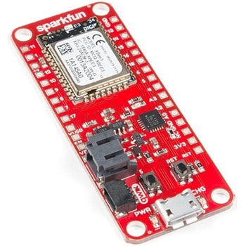
SparkFun Thing Plus - XBee3 Micro Chip Antenna
SPARKFUN¥17,980税込¥19,7781個33日以内出荷Description。The XBee3 Thing Plus is an ultra-capable and easy way for getting into wireless device development. The combination of XBee and Qwiic in a space-conscious design represents a much-needed update to our XBee offering. With 20 I/O pins and Lithium-Polymer Ion battery management, the XBee3 Thing Plus has all the basics for quickly prototyping or developing a connected device such as a remote sensor. The Qwiic connector and JST connector for the battery make for a solder-less option when working with the board which shortens setup time.。The new XBee3 Micro Module provides the classic, near plug and play 802.15.4 2.4GHz wireless connection(Zigbee 3.0 Protocol)that makes it so desirable, but with a new addition of being programmable with MicroPython(32KB of memory available for it). RF data rates up to 250Kbps and 200 ft indoor ranges and up to 4000 ft line-of-sight outdoor range. Communicating with/Configuring the module happens via an AT Command set or the Digi API, X-CTU, both locally or over-the-air. There's even a mobile version of X-CTU now; Digi XBee(R)Mobile.。Note:This variation uses a chip antenna and is not compatible with external antennas.。Get Started With the SparkFun XBee3 Thing Plus Guide。Features。XBee3 Micro Module。Silicon Labs EFR32MG SoC。250Kbps RF, 1Mbps Serial data rates。Indoor/Urban range up to 200 ft(60 m)。Outdoor/RF Line of Sight range up to 4000 ft(1200 m)。+8 dBm transmit power。-103 dBm receiver sensitivity。UART, I2C, SPI Interfaces(SPI currently not available at this time, but broken out on the board)。ISM 2.4GHz Frequency Band(802.15.4)。1MB of memory, 128KB RAM(32KB available for MicroPython)。20 GPIO Pins。Configurable via X-CTU or AT Command set via both USB and Wirelessly(second XBee 3 device required for wireless configuration unless you're using the mobile app)。Qwiic Compatible。On-board charging circuit and connector for 3.3v Lithium Polymer Ion Batteries(see related products for compatible batteries)。2.6VDC - 3.6VDC supply voltage。On-board Chip Antennaアズワン品番67-0429-57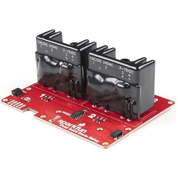
SparkFun Qwiic Dual Solid State Relay
SPARKFUN¥39,980税込¥43,9781個33日以内出荷Description。The SparkFun Qwiic Dual Solid State Relay is a power delivery board that allows users to switch two AC loads from a low power microcontroller using the SparkFun Qwiic connect system. The board features two 25A/250VAC solid state relays that utilize the Zero Cross Trigger method so you can toggle two loads on a 60Hz AC carrier signal on and off up to 120 times per second!。An ATTiny84 acts as the "brain" of the SparkFun Qwiic Dual Solid Relay to accept I2C commands to toggle the two relays as well as a few other special commands. The I2C address of the ATtiny84A is software configurable so, if you have a seriously big power project in mind, you could daisy chain over 100 Qwiic Dual Solid State Relays.。Messing with such high voltage is dangerous! We've included many safety precautions onto the PCB including ground isolation between the relay and other circuitry and a milled out area isolating each side of AC. However, with all the safety precautions included with the SparkFun Qwiic Dual Solid State Relay, this is still a power accessory for users who are experienced around, and knowledgeable about high AC voltage. If you're not comfortable with handling AC voltage in this way, you may want to check out the IoT Power Relay instead.。Note:The relays are rated for a max of 25A with forced air cooling. If you do not have forced air cooling, 10A max through the relays is recommended.。The SparkFun Qwiic connect system is an ecosystem of I2C sensors, actuators, shields and cables that make prototyping faster and less prone to error. All Qwiic-enabled boards use a common 1mm pitch, 4-pin JST connector. This reduces the amount of required PCB space, and polarized connections mean you can't hook it up wrong.。Get Started with the SparkFun Qwiic Dual Solid State Relay Guide。Features。Operating Voltage:2.5-3.6V(3.3V recommended)。I2C Address:0x0A(Default)0x0B(Alternate via jumper select)。Load Voltage Range:12-280VAC。Max Current(Through Relay):25A(240VAC with forced air cooling)。Zero Cross Trigger。Normally Open Circuit Only。2x Qwiic Connectorアズワン品番67-0421-58
USB to TTL Serial Cable 5V VCC
SPARKFUN¥5,498税込¥6,0481個33日以内出荷Description。This is a USB to TTL Serial Cable which allows for a simple way to connect TTL interface devices to USB. The I/O pins of this cable are configured to operate at 3.3V specifically with a Raspberry Pi with each serial pin broken apart. Thanks to its separated pins, this cable is a perfect candidate for powering, connecting, and accessing the login and debug console on an older-version Raspberry Pi.。The FTDI cable is designed around an FT232, which is housed in a USB-A connector. The other side of the cable is terminated with a separated 4-pin connector with the following pinout:RX(Yellow), TX(Orange), VCC(5V)(Red), and GND(Black). A link to the FTDI drivers can be found in the。Documents。section above.。Note:。Please be aware that while the I/O pins in this cableoperate at 3.3V, the VCC pin is 5V. The VCC pin is NOT 3.3V like theI/O pins.アズワン品番67-0420-67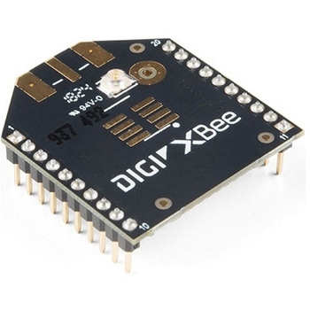
XBee 3 Pro Module - U.FL Antenna
SPARKFUN¥12,980税込¥14,2781個33日以内出荷Description。After years of popularity with the XBee Series 1 and XBee Series 2 Pro Modules, we now have the XBee Series 3 Pro which brings the best of both worlds. XBee 3 not only handles 802.15.4, and ZigBee, but also BLE protocols and you can now talk to the modules over UART or SPI as well. With a 300ft indoor range, or 2mile outdoor/line-of-sight range, you can set up a mesh network to talk to or communicate with various devices around your house, work, or other area.。This module has the familiar XBee package while sporting a U.FL connector to add an antenna. You also get a built in microcontroller so you can also configure and program the modules using MicroPython as well as Digi's XCTU software. With a HCS08 CPU running at up to 50.33MHz, 15x digital I/O pins, and 4x 10-bit ADC pins these modules can even hold their own as a microcontroller.。Note:While these are backwards compatible in many ways with the XBee 1s and 2s, they are not completely compatible. Please see documentation for differences if you plan on adding these to an existing project.。Features。RF 250Kbps, Serial 1Mbps。300ft(indoor)to 2 mile(outdoor)range。Transmit power +19dBM @ 135mA。Receiver Sensitivity -103dBm @ 15mA。4x 10-bit ADC inputs。15x Digital I/O pins。HCS08 CPU at up to 50.33MHz。128/256 bit AES Encryption。2.1V to 3.6V operating voltage。1.7 μA power-down current。Built in RS-485 support。AT command or API frame support。FCC Certifiedアズワン品番67-0429-52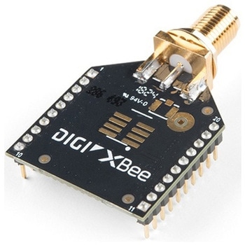
XBee 3 Pro Module - RP-SMA Antenna
SPARKFUN¥11,980税込¥13,1781個33日以内出荷Description。After years of popularity with the XBee Series 1 and XBee Series 2 Pro Modules, we now have the XBee Series 3 Pro which brings the best of both worlds. XBee 3 not only handles 802.15.4, and ZigBee, but also BLE protocols and you can now talk to the modules over UART or SPI as well. With a 300ft indoor range, or 2mile outdoor/line-of-sight range, you can set up a mesh network to talk to or communicate with various devices around your house, work, or other area.。This module has the familiar XBee package while sporting a connector to add an RP-SMA antenna. You also get a built in microcontroller so you can also configure and program the modules using MicroPython as well as Digi's XCTU software. With a HCS08 CPU running at up to 50.33MHz, 15x digital I/O pins, and 4x 10-bit ADC pins these modules can even hold their own as a microcontroller.。Note:While these are backwards compatible in many ways with the XBee 1s and 2s, they are not completely compatible. Please see documentation for differences if you plan on adding these to an existing project.。Features。RF 250Kbps, Serial 1Mbps。300ft(indoor)to 2mile(outdoor)range。Transmit power +19dBM @ 135mA。Receiver Sensitivity -103dBm @ 15mA。4x 10-bit ADC inputs。15x Digital I/O pins。HCS08 CPU at up to 50.33MHz。128/256 bit AES Encryption。2.1V to 3.6V operating voltage。1.7 μA power-down current。Built in RS-485 support。AT command or API frame support。FCC Certifiedアズワン品番67-0429-54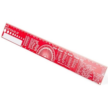
SparkFun PCB Ruler - 12 Inch
SPARKFUN¥3,198税込¥3,5181個33日以内出荷Description。One ruler to rule them all. This is a basic 12 inch ruler, but made from a PCB. We have included a lots of useful information on each side of the ruler that you might use on a daily basis including Wire Gauge holes, transistor diagrams, common fractions, Roman numerals, and metric to imperial conversions. Most importantly, the ruler provides you with a straight line and centimeter markings one side and inch markings on the other side.。You'll also find a small protractor in the middle for all your angle measurement needs. While we figured you have a fairly good idea how to use a ruler we do have a tutorial to explain all the information you'll see!。Get Started with the How to use a Ruler Guide。Features。12 inch PCB ruler with markings down to 0.05" or 1/32"。30.48 cm PCB ruler with markings down to 0.1mm。Electrical Equations such as Ohm's Law and Parallel Resistors。Keyboard Alt Codes。Color Wavelengths。Protractor。Metric Prefix Summary Chart。Metric conversions。Morse Code。Transistor Diagrams。Roman Numerals。Fraction Summary。Wire Guage Chart。Tap and Drill Chart。Size:12"x 1.5"アズワン品番67-0428-67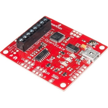
SparkFun OpenScale
SPARKFUN¥11,980税込¥13,1781個33日以内出荷Description。The SparkFun OpenScale is a simple-to-use, open source solution for measuring weight and temperature. It has the ability to read multiple types of load cells and offers a simple-to-use serial menu to configure calibration value, sample rate, time stamp and units of precision.。Simply attach a four-wire or five-wire load cell of any capacity, plug the OpenScale into a USB port, open a terminal window at 9,600bps, and you'll immediately see mass readings. The SparkFun OpenScale will enable you to turn a load cell or four load sensors in a Wheatstone bridge configuration into the DIY weigh scale for your application.。The OpenScale was designed for projects and applications where the load was static(like the beehive in front of SparkFun HQ)or where constant readings are needed without user intervention(for example, on a conveyor belt system). A load cell with an equipped OpenScale can remain in place for months without needing user interaction!。On board the SparkFun OpenScale is the ATmega328P microcontroller, for addressing your communications needs and transferring your data to a serial terminal or to a data logger such as the OpenLog, an FT231 with mini USB, for USB to serial connection; the HX711, a 24-bit ADC for weigh scales; and the TMP102, for recording the ambient temperature of your system. The OpenScale communicates at a TTL level of 9,600bps 8-N-1 by default and possesses a baud rate configurable from 1,200bps to 1,000,000bps.。Get Started with the OpenScale Guide。Features。Operating Voltage:5V。Operating Ampage:80-100mA。Power Cycling above 500ms。Selectable 10SPS or 80SPS Output Data Rate。Local External Temperature Sensors。Fixed Adjustable Gainアズワン品番67-0426-48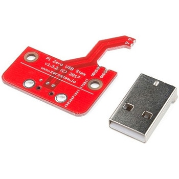
Pi Zero USB Stem
SPARKFUN¥3,398税込¥3,7381個33日以内出荷Description。The Pi Zero USB Stem is a PCB kit that turns a Raspberry Pi Zero into a USB dongle. Once the Stem is installed, your Raspberry Pi can be plugged directly into a computer or USB hub without any additional cables or power supplies. The Raspberry Pi then acts as a USB device using its own Linux kernel gadget drivers to get started.。The Zero Stem is designed to be soldered directly to the USB SMD test pads on the bottom of the Raspberry Pi Zero, needing no wires or pogo pins at all, just solder and a soldering iron! Attaching the stem to your Pi also allows you to create a portable VNC server, or even cluster several Raspberry Pi Zeros with just a USB hub.。The Zero Stem is compatible with the Raspberry Pi Zero v1.3 and the Raspberry Pi Zero W v1.1, but unfortunately it is not compatible with the Raspberry Pi Zero v1.2 or any full-size Raspberry Pi due to their shapes and sizes.。Note:In order for your Pi Zero to function as a USB device with this Stem, you will need to configure it to act as one. You will be able to find these instructions in the Documentations tab under "How to OTG Fast".アズワン品番67-0424-13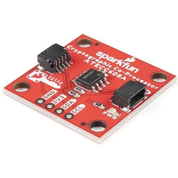
SparkFun Cryptographic Co-Processor Breakout - ATECC608A Qwiic
SPARKFUN¥1,498税込¥1,6481個33日以内出荷。Description。Product Restrictions:To access certain features of the ATECC608A, users will need to contact Microchip and sign an NDA contract to obtain the complete datasheet. Due to the required NDA - technical support, an Arduino library, and hookup guide are not provided for users on this product.。The SparkFun ATECC608A Cryptographic Co-processor Breakout allows you to add strong security to your IoT node, edge device, or embedded system. This includes。a。symmetric。authentication,。symmetric。AES-128 encryption/decryption, and much more. As stated above, the ATECC608A has limited Arduino support and the complete datasheet is under NDA with Microchip.。This breakout board includes two Qwiic ports for plug and play functionality. Utilizing our handy Qwiic system, no soldering is required to connect it to the rest of your system. However, we still have broken out 0.1"-spaced pins in case you prefer to use a breadboard. The ATECC608A chip is capable of many cryptographic processes, including, but not limited to:Creating and securely storing unique asymmetric key pairs based on Elliptic Curve Cryptography(FIPS186-3).。AES-128:Encrypt/Decrypt, Galois Field Multiply for GCM。Creating and verifying 64-byte digital signatures(from 32-bytes of message data).。Creating a shared secret key on a public channel via Elliptic Curve Diffie-Hellman Algorithm.。SHA-256 HMAC Hash including off-chip context save/restore。Internal high quality FIPS random number generator.。Embedded in the chip is a 10Kb EEPROM array that can be used for storing keys, certificates, data, consumption logging, and security configurations. Access to the sections of memory can then be restricted and the configuration locked to prevent changes. Each ATECC608A Breakout ships with a guaranteed unique 72-bit serial number and includes several security features to prevent physical attacks on the device itself, or logical attacks on the data transmitted between the device.。A summary datasheet for the ATECC608A is available here. The full datasheet is under NDA with Microchip. You will need to contact them for access to the entire datasheet. Meanwhile, the ArduinoATECCX08 Library currently only supports the ATECC608A with SAMD21 Arduino boards.。We do have much more support for the ATECC508A version of this chip. Please check out our ATECC508A Hookup Guide and Arduino Library(which includes six examples). This will get you familiar with the basics of elliptic curve cryptography and signing/verifying data with the ATECC508A version of the chip.。Note:The I2C address of the ATECC608A is 0x60 and is software-configurable to any address. A multiplexer/Mux is required to communicate to multiple ATECC608A sensors at the default address when on a single bus. If you need to use more than one ATECC608A sensor at the default address, consider using the Qwiic Mux Breakout.。Note:The ATECC608A can be only configured once before it is。PERMANENTLY。locked。. It is advisable that users purchase multiple boards in order to use other configurations and explore the advanced functions of the ATECC608A.。Additionally, this board。IS。capable of encrypting and decrypting data. However, to access these additional features, you will need to contact Microchip and sign an NDA contract to obtain the complete datasheet.。It is recommended that an SparkFun RedBoard Turbo - SAMD21 Development Board is used with this product due to the buffer size required on the I2C bus.。The SparkFun Qwiic Connect System is an ecosystem of I2C sensors, actuators, shields and cables that make prototyping faster and less prone to error. All Qwiic-enabled boards use a common 1mm pitch, 4-pin JST connector. This reduces the amount of required PCB space, and polarized connections mean you can't hook it up wrong.。。Features。Operating Voltage:2.0V-5.5V(。Default on Qwiic System:3.3V。)。Active Current Draw(for ATECC608A):16 mA。Sleep Current(for ATECC608A):<150 nA。Guaranteed Unique 72-bit Serial Number。10 Kb EEPROM Memory for Keys, Certificates, and Data。Storage for up to 16 Keys。256-bit Key Length。Internal High-Quality FIPS Random Number Generator(RNG)。Configurable I2C Address(7-bit):0x60(。Default。)アズワン品番67-0423-59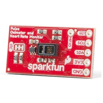
SparkFun Pulse Oximeter and Heart Rate Sensor - MAX30101 & MAX32664 Qwiic
SPARKFUN¥13,980税込¥15,3781個33日以内出荷Description。The SparkFun Pulse Oximeter and Heart Rate Sensor is an I2C based biometric sensor, utilizing two chips from Maxim Integrated:the MAX32664 Biometric Sensor Hub and the MAX30101 Pulse Oximetry and Heart Rate Module. While the latter does all the sensing, the former is an incredibly small and fast Cortex M4 processor that handles all of the algorithmic calculations, digital filtering, pressure/position compensation, advanced R-wave detection, and automatic gain control. We've provided a Qwiic connector to easily connect to the I2C data lines but you will also need to connect to two additional lines. This board is very small, measuring at 1in×0.5in(25.4mm×12.7mm), which means it will fit nicely on your finger without all the bulk.。The MAX30101 does all the sensing by utilizing its internal LEDs to bounce light off the arteries and arterioles in your finger's subcutaneous layer and sensing how much light is absorbed with its photodetectors. This is known as photoplethysmography. This data is passed onto and analyzed by the MAX32664 which applies its algorithms to determine heart rate and blood oxygen saturation(SpO2). SpO2 results are reported as the percentage of hemoglobin that is saturated with oxygen. It also provides useful information such as the sensor's confidence in its reporting as well as a handy finger detection data point. To get the most out of the sensor we've written an Arduino Library to make it easy to adjust all the possible configurations.。The SparkFun Qwiic connect system is an ecosystem of I2C sensors, actuators, shields and cables that make prototyping faster and less prone to error. All Qwiic-enabled boards use a common 1mm pitch, 4-pin JST connector. This reduces the amount of required PCB space, and polarized connections mean you can't hook it up wrong.。Get Started with the Pulse Oximeter and Heart Rate Monitor Hookup Guide。Features。SparkFun Pulse Oximeter and Heart Rate Sensor。MAX30101 and MAX32664 sensor and sensor hub。Qwiic connectors for power and I2C interface。I2C Address:0x55。MAX30101 - Pulse Oximeter and Heart-Rate Sensor。Heart-Rate Monitor and Pulse Oximeter Sensor in LED Reflective Solution。Integrated Cover Glass for Optimal, Robust Performance。Ultra-Low Power Operation for Mobile Devices。Fast Data Output Capability。Robust Motion Artifact Resilience。MAX32664 - Ultra-Low Power Biometric Sensor Hub。Biometric Sensor Hub Solution。Finger-Based Algorithms Measure Pulse Heart Rate and Pulse Blood Oxygenation Saturation(SpO2)。Both Raw and processed data are available。Basic Peripheral mix optimizes size and performanceアズワン品番67-0426-96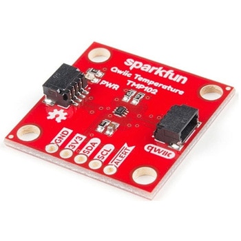
SparkFun Digital Temperature Sensor - TMP102 Qwiic
SPARKFUN¥2,398税込¥2,6381個33日以内出荷Description。We all like to know the temperature, right? Well, with the SparkFun TMP102 Digital Temperature Sensor, we've made it just about as easy as it gets. Based on the original Digital Temperature Sensor Breakout TMP102, we've added Qwiic connectors to bring this board into our plug-and-play Qwiic Ecosystem and added an address jumper instead of breaking out the address pin. However, we still have broken out 0.1"-spaced pins in case you prefer to use breadboard.。The TMP102 itself is an easy-to-use digital temperature sensor from Texas Instruments. While some temperature sensors use an analog voltage to represent the temperature, the TMP102 uses the I2C bus of the Arduino to communicate the temperature.。The TMP102 is capable of reading temperatures to resolution of 0.0625℃, and is accurate up to 0.5℃. The breakout has built-in 4.7kΩ pull-up resistors for I2C communications and runs from 1.4V to 3.6V. I2C communication uses an open drain signaling, so there is no need to use level shifting.。The SparkFun Qwiic Connect System is an ecosystem of I2C sensors, actuators, shields and cables that make prototyping faster and less prone to error. All Qwiic-enabled boards use common 1mm pitch, 4-pin JST connector. This reduces the amount of required PCB space, and polarized connections mean you can't hook it up wrong.。Get Started with the Qwiic TMP102 Digital Temperature Sensor Guide。Features。Uses the I2C interface。I2C Address:0x48 by default。(Three additional addresses available, as well)。12-bit, 0.0625℃ resolution。Typical temperature accuracy of ±0.5℃。3.3V sensor。Supports up to four TMP102 sensors on the I2C bus at time。2x Qwiic Connectorsアズワン品番67-0427-17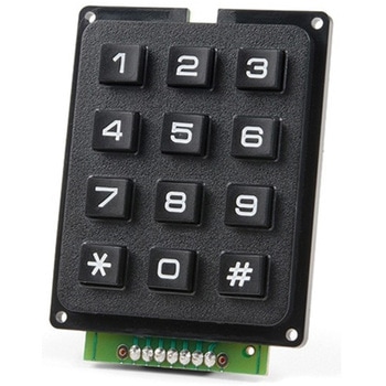
SparkFun Qwiic Keypad - 12 Button
SPARKFUN¥4,198税込¥4,6181個33日以内出荷Description。Keypads are very handy input devices, but who wants to tie up seven GPIO pins, wire up handful of pull-up resistors, and write firmware that wastes valuable processing time scanning the keys for inputs? The SparkFun Qwiic Keypad comes fully assembled and makes the development process for adding 12 button keypad easy. No voltage translation or figuring out which I2C pin is SDA or SCL, just plug and go! Utilizing our handy Qwiic system, no soldering is required to connect it to the rest of your system. However, we still have broken out 0.1"-spaced pins in case you prefer to use breadboard.。Each of the keypad's 12 buttons has been labeled 1, 2, 3, 4, 5, 6, 7, 8, 9, 0, *, and and has been formatted to into the same layout as telephone keypad with each keypress resistance ranging between 10 and 150 Ohms. The Qwiic Keypad reads and stores the last 15 button presses in First-In, First-Out(FIFO)stack, so you don't need to constantly poll the keypad from your microcontroller. This information, then, is accessible through the Qwiic interface. The SparkFun Qwiic Keypad even has software configurable I2C address so you can have multiple I2C devices on the same bus.。NOTE:The I2C address of the Qwiic Keypad is 0x4B and is jumper selectable to 0x4A(software-configurable to any address). multiplexer/Mux is required to communicate to multiple Qwiic Keypad sensors on single bus. If you need to use more than one Qwiic Keypad sensor consider using the Qwiic Mux Breakout.。The SparkFun Qwiic connect system is an ecosystem of I2C sensors, actuators, shields and cables that make prototyping faster and less prone to error. All Qwiic-enabled boards use common 1mm pitch, 4-pin JST connector. This reduces the amount of required PCB space, and polarized connections mean you can't hook it up wrong.。Get Started with the SparkFun Qwiic Keypad Hookup Guide。Features。Software Selectable Slave Address。Low Power ATtiny85 controller。Button Presses w/ Time Stamp。Default I2C Address:0x4B。2x Qwiic Connectorアズワン品番67-0421-41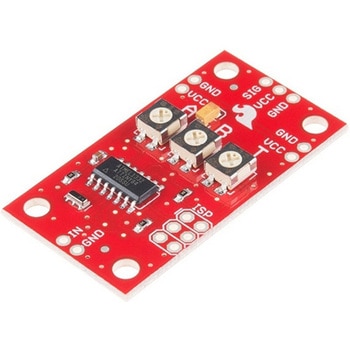
SparkFun Servo Trigger - Continuous Rotation
SPARKFUN¥4,898税込¥5,3881個33日以内出荷。Description。The SparkFun Continuous Rotation(CR)Servo Trigger is a small robotics board that simplifies the control of hobby RC servo motors. When an external switch or logic signal changes state, the CR Servo Trigger is able to tell an attached servo motor to move from position A to position B. To use the CR Servo Trigger, you simply connect a hobby servo and a switch, then use the on-board potentiometers to adjust the start/stop positions and the transition time. You can use a hobby servo in your projects without having to do any programming!。When we introduced the original Servo Trigger, we mentioned that it could be reprogrammed to be more useful with continuous rotation servo motors. But reprogramming the firmware is somewhat tedious, and users asked for a Servo Trigger preprogrammed with the continuous rotation logic. With this little board you will be provided an easy way to deploy continuous rotation servos into your projects!。The heart of the CR Servo Trigger is an Atmel ATtiny84 microcontroller, running a small program that implements the servo control features designed for continuous rotation servos. On board each of these CR Servo Triggers you will find three potentiometers:"A" sets the position the servo sits in while the switch is open, "B" sets the position the servo moves to when the switch is closed, and "T" sets the time it takes to get from A to B and back.。Compared with a servo motor, the CR Servo Trigger board draws very little current, roughly 5mA at 5V. Be sure to note that if you're using the CR Servo Trigger to control your motor, the absolute maximum supply voltage that should be applied is 5.5 VDC. Additionally, the SparkFun CR Servo Trigger is designed to make it easy to daisy chain boards - you can simply connect the VCC and GND pads on adjacent boards to each other.。Note:This idea originally came from our friend in the Oakland area, CTP. If you see him, please give him a high-five for us.。SparkFun CR Servo Trigger Hookup Guide。Features。Recommended Voltage:5VDC。Max Voltage:5.5VDC。Current Draw:5mA。Control Continuous Rotation Servos。Three Control Settings。A - sets the position the servo sits in while the switch is open。B - sets the position the servo moves to when the switch is closed。C - sets the time it takes to get from A to B and back。Easy Control with Potentiometers。Configurable Input Polarity。Configurable Response Mode。Compatible with Analog Servos。ISP Header Pins Available for Reprogramアズワン品番67-0429-21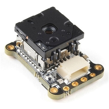
PureThermal Mini Pro JST-SR with FLIR Lepton 3.5
SPARKFUN¥129,800税込¥142,7801個33日以内出荷Description。The new PureThermal Mini Pro JST-SR with Thermal by FLIR is a hackable thermal camera for the FLIR Lepton thermal imaging camera core. Just like its PureThermal 2 predecessor, it ships pre-configured to operate as a plug-and-play UVC 1.0 USB thermal webcam that will work with standard webcam and video apps on all major platforms using a JST-SR to USB Cable, or your own custom cable. For developers, its reference firmware and viewer software are open source.。It has multiple connection options such as solder straight to the board or a custom cable using the JST-SR port. The PTMini Pro also features four mounting holes, less complex circuitry, and perhaps best of all, USB DFU. This is a development kit ready to be embedded into a production system.。Each board comes with a FLIR Lepton 3.5.。The FLIR Lepton(R)is a radiometric-capable LWIR camera solution that is smaller than a dime, fits inside a smartphone, and is one tenth the cost of traditional IR cameras. Using focal plane arrays of either 160x120 or 80x60 active pixels, Lepton easily integrates into native mobile-devices and other electronics as an IR sensor or thermal imager. The radiometric Lepton captures accurate, calibrated, and noncontact temperature data in every pixel of each image.。Features。PureThermal:Compatible with all production FLIR Leptons, including radiometric 2.5 and 3.5 cores。9 Hz color video over usb using the USB UVC class。STM32F412 ARM microprocessor - execute on-board image processing without need for an external system。Open source reference firmware:GroupGets PureThermal Github。Works with GetThermal - our custom open source thermal video display software for macOS and Linux with radiometric support。DFU over USB using a JST-SR port to USB cable, or a modified USB cable and the through holes.。Four mounting holes。Compact form-factor ready to be embedded into production systems。FLIR Lepton 3.5:Thermal sensitivity:< 50 mK(0.050℃)。Spectral Range:8 - 14 microns(nominal)Long Wave Infrared(LWIR)。Resolution:160h×120v pixels。Radiometric Accuracy - High Gain Mode:Greater of +/- 5℃ or 5%(typical); Low Gain Mode:Greater of +/- 10℃ or 10%(typical)。Scene Dynamic Range - High Gain Mode:-10° to +140℃; Low Gain Mode:-10° to +400℃(at room temperature), -10° to +450℃(typical)。Pixel Size:12 micrometers。Frame Rate:8.7 Hz(effective)。Output Format:User-selectable 14-bit, 8-bit(AGC applied), or 24-bit RGB(AGC and colorization applied)。Horizontal Field of View(HFOV):57°。Lens Type:f/1.1。Size(w×l×h):10.50×12.70×7.14 mm。Weight:0.9 grams。Power Consumption:150 mW typical, 650 mW during shutter event, 5mW standby。Optimum Operating Temperature Range:-10℃ to + 80℃アズワン品番67-0423-44