カテゴリ
- 学童・教育用品(16)
- 制御機器(1)
絞り込み
ブランド
- SPARKFUN
- 不二ラテックス(148)
- 鈴木ラテックス(44)
- KEMET(31)
- ラブコン(30)
- ホンダ(29)
- RS PRO(25)
- azbil(旧:山武)(13)
- onsemi(10)
- 日野自動車(9)
- 三菱ふそう(8)
- SKF(日本エスケイエフ)(6)
- Seeed Studio(6)
- Hutchinson(6)
- AMPHENOL(5)
- SKC(環境測定)(5)
- NIPRO(ニプロ)(4)
- APEM(4)
- DiodesZetex(4)
- ブランドをもっと見る
「latex」の検索結果
LOAD CELL AMP HX711
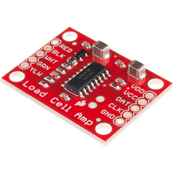
SPARKFUN¥3,500税込¥3,8501個33日以内出荷。Description。The SparkFun Load Cell Amplifier is a small breakout board for the HX711 IC that allows you to easily read load cells to measure weight. By connecting the amplifier to your microcontroller you will be able to read the changes in the resistance of the load cell, and with some calibration you'll be able to get very accurate weight measurements. This can be handy for creating your own industrial scale, process control or simple presence detection.。This version of the SparkFun Load Cell Amplifier features a few changes that you specifically asked for! We have separated the analog and digital supply, as well as added a 3.3uH inductor and a 0.1uF filter capacitor for digital supply. Need even more? Checkout the SparkFun Qwiic Scale. It has all the features of the HX711 but with additional library support, a true I2C interface, and no soldering required!。The HX711 uses a two-wire interface(Clock and Data)for communication. Any microcontroller's GPIO pins should work, and numerous libraries have been written, making it easy to read data from the HX711. Check the hookup guide below for more information.。Load cells use a four-wire Wheatstone bridge configuration to connect to the HX711. These are commonly colored RED, BLK, WHT, GRN and YLW. Each color corresponds to the conventional color coding of load cells:Red(Excitation+ or VCC)。Black(Excitation- or GND)。White(Amplifier-, Signal- or Output-)。Green(A+, S+ or O+)。Yellow(Shield)。The YLW pin acts as an optional input that is not hooked up to the strain gauge but is utilized to ground and shield against outside EMI(electromagnetic interference). Please keep in mind that some load cells might have slight variations in color coding.。Note:Special thanks to Bodge for supplying the Library for the HX711!。Get Started with the HX711 Load Cell Amplifier Guide。Features。Operation Voltage:2.7V--5V。Operation Current:< 1.5mA。Selectable 10SPS or 80SPS output data rate。Simultaneous 50 and 60Hz supply rejectionアズワン品番67-0362-17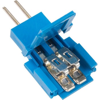
Amphenol FCI Clincher Connector 2 Position, Male
SPARKFUN¥1,098税込¥1,2081個33日以内出荷Description。These Clincher connectors from Amphenol FCI can be used to terminate Flat Flexible Cables(FFCs)to an easy-to-use standard header. Simply insert the end of the cable into the connector and press it closed. The teeth inside the connector willアズワン品番67-0351-04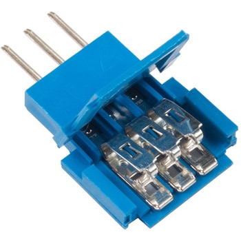
電子機器接続端子
SPARKFUN¥549税込¥6041個33日以内出荷Description。These Clincher connectors from Amphenol FCI can be used to terminate Flat Flexible Cables(FFCs)to an easy-to-use standard header. Simply insert the end of the cable into the connector and press it closed. The teeth inside the connector will "clinch" around the conductors and break them out to three male 0.1" spaced pin headers!。Though the Clincher connector can be used with FFCs, we also like to use them with our FlexiForce sensors and other flex/force sensors found in the。Recommended Products。section below.。Note:。Please be aware that we will not be able to accept returns on this connector if it has been closed. Sorry for any inconvenience this may cause.アズワン品番67-0395-68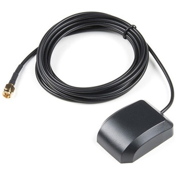
GPS/GNSS Magnetic Mount Antenna - 3m SMA
SPARKFUN¥4,998税込¥5,4981個33日以内出荷Description。Normal GPS antennas are optimized for the US based GPS reception which is great but with more and more modules capable of tracking additional constellations(termed GNSS receivers)you're going to need the right antenna! This exceptional GPS/GNSS antenna is designed for both GPS and GLONASS reception. When used in conjunction with the SparkFun GPS ground plate this antenna achieved excellent TTFF and SIV statistics for both GPS and GLONASS constellations. The magnetic mount allows it to be easily mounted to a metal base such as a ground plate or car roof. The antenna is terminated with a 3m cable and standard SMA connector.。We recommend this antenna for RTK use when combined with the ground plate. If you need Beidou reception and additional gain consider the GPS/GNSS embedded antenna.。Features。Dimensions:50x38x17mm。Weight:75g including 3m cable。Frequency Range:1575 - 1610MHz。GPS Center Frequency:1575.42MHz。GLONASS Center Frequency:1602MHz。LNA Voltage:3 to 5VDC。LNA Gain:28dB。LNA Current:10mA。Termination Connector:SMA。Impedance:50Ω。Right hand polarization。Cable Length:3 meterアズワン品番67-0423-72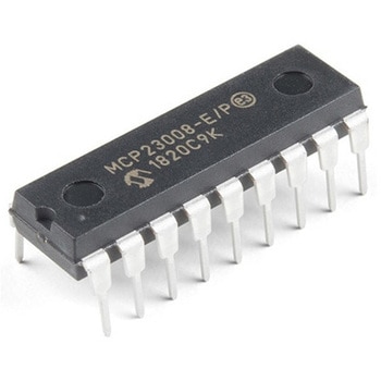
I/O Expander - MCP23008
SPARKFUN¥639税込¥7031個33日以内出荷。Description。Add another eight pins to your microcontroller using a MCP23008 port expander. The MCP23008 uses two I2C pins which can be shared with other I2C devices, and in exchange gives you eight general purpose pins. You can set each of eight pins to be input, output, or input with a pullup. There's even the ability to get an interrupt via an external pin when any of the inputs change so you don't have to keep polling the chip.。Use this chip from 2.7-5.5V(good for any 3.3V or 5V setup), and you can sink/source up to 20mA from any of the I/O pins so this will work for LEDs and such. Team it up with a high-power MOSFET if you need more juice. DIP package means it will plug into any breadboard or perfboard.。You can set the I2C address by tying the ADDR0-2 pins to power or ground, for up to eight unique addresses. That means eight chips can share a single I2C bus - that's 64 I/O pins!。Features。8-bit remote bidirectional I/O port。High-speed I2C interface(MCP23008)。Hardware address pins。Configurable interrupt output pin。Configurable interrupt source。Polarity Inversion register for input port data polarity config.。External reset input。Low standby current:1 μA(max.)・ Operating voltage:。1.8V to 5.5V @ -40℃ to +85℃ I2C @ 100 kHz SPI @ 5 MHz。2.7V to 5.5V @ -40℃ to +85℃ I2C @ 400 kHz SPI @ 10 MHz。4.5V to 5.5V @ -40℃ to +125℃ I2C @ 1.7 kHz SPI @ 10 MHzアズワン品番67-0421-32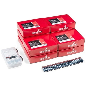
SparkFun Inventor's Kit for micro:bit v2 Lab Pack
SPARKFUN¥159,800税込¥175,7801個33日以内出荷Description。The SparkFun Inventor's Kit for micro:bit v2 Lab Pack includes 10 complete micro:bit v2 Inventor's Kits, an SIK Refill Pack and 25 AAA-sized batteries to get your students started in the world of electronics. The SIKs inside the Lab Pack have everything you need, including micro:bit v2s, connector breakouts, breadboards and all the cables and accessories to hook up all the projects listed in our online Experiment Guide.。The kit does not require any soldering and is recommended for all users, from beginners to engineering students. We have provided a complete Experiment Guide in the Documents tab for you to check out now! If you are new to teaching electronics or have taught with the original SparkFun Inventor's Kit and are looking for something new, the SIK for micro:bit v2 is the perfect kit for you!。SparkFun packages everything educators need to get started with this platform in a variety of classroom and makerspace settings with diverse student populations. The hardware boards, cables and extra parts come pre-packaged, and our online support materials --- including an online Experiment Guide(to be updated)--- help you bring the power of the open source community to your classroom. Examples and curriculum materials are available from SparkFun and Arduino, as well as from other educators involved in this growing maker movement.。The micro:bit is a pocket-sized computer that lets you get creative with digital technology. Between the micro:bit and our shield-like bit boards you can do almost anything while coding, customizing and controlling your micro:bit from almost anywhere! You can use your micro:bit for all sorts of unique creations, from robots to musical instruments and more. At half the size of a credit card, this versatile board has vast potential!アズワン品番67-0424-93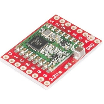
SparkFun RFM69 Breakout 434MHz
SPARKFUN¥4,398税込¥4,8381個33日以内出荷Description。This is the SparkFun RFM69 Breakout, a small piece of tech that breaks out all the pins available on the RFM69HCW module as well as making the transceiver easy to use. The RFM69HCW is an inexpensive and versatile radio module that operates in the unlicensed ISM(Industry, Science and Medicine)radio band. It's perfect for building inexpensive short-range wireless networks of sensors and actuators for home automation, citizen science and more.。This RFM69HCW operates on the 434MHz frequency and is capable of transmitting at up to 100mW and up to 300kbps, but you can change both of those values to fit your application. For example, you can maximize range by increasing the transmit power and reducing the data rate, or you can reduce both for short-range sensor networks that sip battery power. At full power and with simple wire antennas, we can get messages from one side of a large office building to the other through numerous internal walls. In open air you can reach 500 meters or more. With more complex antennas and modulation schemes, similar parts have successfully transmitted from space to the ground(by very smart amateur radio enthusiasts; your mileage may vary)!。The RFM69HCW uses an SPI(Serial Peripheral Interface)to communicate with a host microcontroller, and several good Arduino libraries are available. It supports up to 256 networks of 255 nodes per network, features AES encryption to keep your data private, and transmits data packets up to 66 bytes long.。SparkFun sells two versions of the RFM69HCW:a 915MHz version and this 434MHz version. Although the ISM band is license-free, the band itself is different in different areas. Very roughly, 915MHz is for use in the Americas, and the 434MHz version is for use in Europe, Asia and Africa. Check your local regulations for other areas.。Get Started with the RFM69HCW Hookup Guide。Features。Transmit power:-18dBm(0.016mW)to +20dBm(100mW)in 1dBm steps。Receive sensitivity:down to -120dBm at 1.2kbps。Modulation types:FSK GFSK MSK GMSK OOK。Bit rates(FSK):1.2kbps to 300kbps。Voltage range:1.8V to 3.6V。Current consumption:0.1uA sleep, 1.25mA standby, 16mA receive, 130mA transmit(max)。Encryption:AES 128-bit(optional)。Packet buffer(FIFO):66 bytes。0.8"×1.1"アズワン品番67-0429-33
LEDドライバ
SPARKFUN¥2,498税込¥2,7481個33日以内出荷Description。This is the FemtoBuck, a small-size single-output constant current LED driver. Each FemtoBuck has the capability to dim a single high-power channel of LEDs from 0-350mA at up to 36V while the dimming control can be either accessed via PWM or analog signal from 0-2.5V. This board is based off of the PicoBuck LED Driver, developed in collaboration with Ethan Zonca, except instead of blending three different LEDs on three different channels the FemtoBuck controls just one.。For the FemtoBuck, we've increased the voltage ratings on the parts to allow the input voltage to cover the full 36V range of the AL8805 driver. Since the FemtoBuck is a constant current driver, the current drawn from the supply will drop as supply voltage rises. In general, efficiency of the FemtoBuck is around 95%, depending on the input voltage. On board each FemtoBuck you will find two inputs for both power input and dimming control pins and an area to install a 3.5mm screw terminal. Finally at either side of the board you will find small indents or "ears" which will allow you to use a zip tie to secure the wires to the board after soldering them down. This version of the FemtoBuck is equipped with a small solder jumper that can be closed with a glob of solder to double the output current from 330mA to 660mA.アズワン品番67-0477-97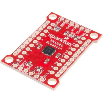
SparkFun 16 Output I/O Expander Breakout - SX1509
SPARKFUN¥2,198税込¥2,4181個33日以内出荷Description。Are you low on I/O? No problem! The SX1509 Breakout is 16-channel GPIO expander with an I2C interface that means with just two wires, your microcontroller can interface with 16 fully configurable digital input/output pins. But the SX1509 can do so much more than just simple digital pin control. It can produce PWM signals, so you can dim LEDs. It can be set to blink or even breathe pins at varying rates. This breakout is similar to multiplexer or "mux," in that it allows you to get more IO from less pins. And, with built-in keypad engine, it can interface with up to 64 buttons set up in an 8x8 matrix.。Two headers at the top and bottom of the breakout board function as the input and control headers to the board. This is where you can supply power to the SX1509, and where your I2C signals SDA and SCL will terminate. GPIO and power buses are broken out in every-which direction, and configurable jumpers cover most of the rest of the board.。Since the I/O banks can operate between 1.2V and 3.6V(5.5V tolerant)independent of both the core and each other, this device can also work as level-shifter. The SX1509 breakout makes it easy to prototype so you can add more I/O onto your Arduino or I/O limited controller. We've even spun up an Arduino Library to get you started!。Features。Enable Direct Level Shifting Between I/O Banks and Host Controller。5.5V Tolerant I/Os, Up to 15mA Output Sink on All I/Os。Integrated LED Driver with Intensity Control。On-Chip Keypad Scanning Engine Supports Up to 8x8 Matrix(64 Keys)。16 Channels of True Bi-directional Style I/O。400kHz I2C Compatible Slave Interfaceアズワン品番67-0419-88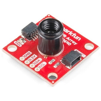
SparkFun IR Array Breakout - 55 Degree FOV, MLX90640 Qwiic
SPARKFUN¥22,980税込¥25,2781個33日以内出荷Description。It's time to say hip hip array for this IR Breakout! The MLX90640 SparkFun IR Array Breakout is equipped with a 32x24 array of thermopile sensors creating, in essence, a low resolution thermal imaging camera. With this breakout you can detect surface temperatures from many feet away with an accuracy of ±1.5℃(best case). To make it even easier to get your infrared image, all communication is enacted exclusively via I2C, utilizing our handy Qwiic system. However, we still have broken out 0.1"-spaced pins in case you prefer to use a breadboard.。This specific IR Array Breakout features a。55°x35°。field of view with a temperature measurement range of -40℃-300℃. The MLX90640 IR Array has pull up resistors attached to the I2C bus; both can be removed by cutting the traces on the corresponding jumpers on the back of the board. Please be aware that the MLX90640 requires complex calculations by the host platform so a regular Arduino Uno(or equivalent)doesn't have enough RAM or flash to complete the complex computations required to turn the raw pixel data into temperature data. You will need a microcontroller with 20,000 bytes or more of RAM. To achieve this, we recommend a Teensy 3.1 or above.。The SparkFun Qwiic connect system is an ecosystem of I2C sensors, actuators, shields and cables that make prototyping faster and less prone to error. All Qwiic-enabled boards use a common 1mm pitch, 4-pin JST connector. This reduces the amount of required PCB space, and polarized connections mean you can't hook it up wrong.。Get Started with the SparkFun IR Array Breakout Guide。Features。Operating Voltage:3V-3.6V。Current Consumption:~18mA。Field of View:55°x35°。Measurement Range:-40℃-300℃。Resolution:±1.5℃。Refresh Rate:0.5Hz-64Hz。I2C Address:0x33。2x Qwiic Connection Portsアズワン品番67-0426-88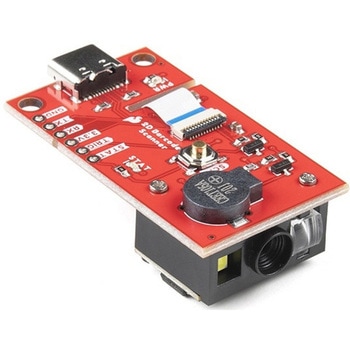
SparkFun 2D Barcode Scanner Breakout
SPARKFUN¥20,980税込¥23,0781個33日以内出荷。Description。The SparkFun 2D Barcode Scanner Breakout is a nifty little breakout board featuring the DE2120 barcode scanner module from DYScan. The DE2120 reads 20 different barcode symbologies(both 1D and 2D)using a camera coupled with on-board image processing to identify and decode everything from UPC codes to QR codes. The module also features two LEDs:one for illumination and one to project the red line that you're used to seeing from laser-based scanners.。This breakout board makes it easy to explore all of the capabilities of the DE2120 without dealing with finicky flat flex cables. The scanner's USB interface is exposed via the on-board USB-C connector. A buzzer and status LED are connected to the module through appropriate drive circuits and a push button tactile switch is provided on the "trigger" pin. When you're ready to incorporate the module into your embedded project, you can leverage the 5 pin header for direct access to the TTL serial pins, power pins, and trigger input.。The module can be configured either by using the serial interface or by scanning command barcodes found in the Settings Manual.。All keyboard, HID, and serial can be transmitted over the single USB-C connector. The DE2120 has the unique ability to enumerate all three protocols including a CDC serial driver so the device appears as a standard COM port.。Get Started with the 2D Barcode Scanner Breakout Hookup Guide。Features。USB-C Connector for USB HID Interface and Virtual COM port。Reads 20 different symbologies。1D Symbologies。UPC-A。UPC-E。EAN-8。EAN-13。Code 128。GS1-128。Code 39。Code 93。Code 11。Interleaved 2-of-5。Matrix 2-of-5。Industrial 2-of-5。Codabar。MSI。GS1 DataBar。Datalogic 2-of-5。2D Symbologies。QR Code。Data Matrix。PDF 417。Micro PDF 417。Aztec Codeアズワン品番67-0430-36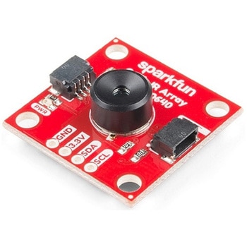
SparkFun IR Array Breakout - 110 Degree FOV, MLX90640 Qwiic
SPARKFUN¥22,980税込¥25,2781個33日以内出荷Description。It's time to say hip hip array for this IR Breakout! The MLX90640 SparkFun IR Array Breakout is equipped with a 32x24 array of thermopile sensors creating, in essence, a low resolution thermal imaging camera. With this breakout you can detect surface temperatures from many feet away with an accuracy of ±1.5℃(best case). To make it even easier to get your low-resolution infrared image, all communication is enacted exclusively via I2C, utilizing our handy Qwiic system. However, we still have broken out 0.1"-spaced pins in case you prefer to use a breadboard.。This specific IR Array Breakout features a 110°x75° field of view with a temperature measurement range of -40℃-300℃. The MLX90640 IR Array has pull up resistors attached to the I2C bus; both can be removed by cutting the traces on the corresponding jumpers on the back of the board. Please be aware that the MLX90640 requires complex calculations by the host platform so a regular Arduino Uno(or equivalent)doesn't have enough RAM or flash to complete the complex computations required to turn the raw pixel data into temperature data. You will need a microcontroller with 20,000 bytes or more of RAM. To achieve this, we recommend a Teensy 3.1 or above.。Note:The I2C address of the MLX90640 is 0x33 and is hardware defined. A multiplexer/Mux is required to communicate to multiple MLX90640 sensors on a single bus. If you need to use more than one MLX90640 sensor consider using the Qwiic Mux Breakout.。The SparkFun Qwiic connect system is an ecosystem of I2C sensors, actuators, shields and cables that make prototyping faster and less prone to error. All Qwiic-enabled boards use a common 1mm pitch, 4-pin JST connector. This reduces the amount of required PCB space, and polarized connections mean you can't hook it up wrong.。Get Started with the SparkFun IR Array Breakout Guide。Features。Operating Voltage:3V-3.6V。Current Consumption:~18mA。Field of View:110°x75°。Measurement Range:-40℃-300℃。Resolution:±1.5℃。Refresh Rate:0.5Hz-64Hz。I2C Address:0x33。2x Qwiic Connection Portsアズワン品番67-0426-87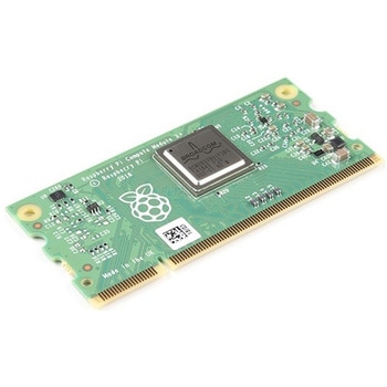
Raspberry Pi Compute Module 3+ Lite
SPARKFUN¥10,980税込¥12,0781個33日以内出荷Description。The Raspberry Pi Compute Module 3+ Lite contains the guts of a Raspberry Pi 3 Model B+(the BCM2837 processor and 1GB LPDDR2 RAM). This module allows a designer to leverage the Raspberry Pi hardware and software stack in their own custom systems and form factors. In addition this module has extra IO interfaces over and above what is available on the Raspberry Pi model A/B boards, opening up more options for the designer.。This is all integrated onto a small(67.6mm×31mm)board that fits into a standard DDR2 SODIMM connector. You get the full flexibility of the BCM2837 SoC(which means that many more GPIOs and interfaces are available than with a standard Raspberry Pi), and designing the Module into a custom system should be relatively straightforward because all the tricky bits have been put onto the Module itself.。The CM3+ Lite product is the same as CM3+ except the eMMC Flash is not fitted, and the SD/eMMC interface pins are available for the user to connect their own SD/eMMC device. Note that the CM3+ is electrically identical and, with the exception of higher CPU z-height, physically identical to the legacy CM3 products.。Note:The CM3+ modules require a software/firmware image dated November 2018 or newer to function correctly.。Features。Broadcom BCM2837B0, Cortex-A53(ARMv8)64-bit SoC @ 1.2GHz。1GB LPDDR2 SDRAM。Operating Supply Voltage:1.8V, 3.3V。Minimum Operating Temperature:-25C。Maximum Operating Temperature:+80C。HDMI, MIPI, USB, and GPIO interfaces on edge connectorアズワン品番67-0423-17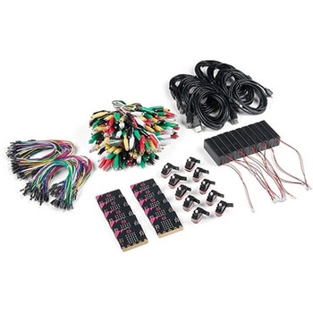
SparkFun Educator Lab Pack for micro:bit v2
SPARKFUN¥109,800税込¥120,7801個33日以内出荷Description。The micro:bit v2 Educator's Lab Pack includes 10 micro:bit v2 boards and everything you need to get you started with the new learning platform. The Lab Pack has everything you need, including micro:bits, cables, battery packs and a few parts to experiment with. This package provides an easy way to introduce your students to the micro:bit without any difficulty or parts hunting.。SparkFun packages everything educators need to get started with the micro:bit in a variety of classroom settings and learning environments. The hardware boards, cables and extra parts come pre-packaged. Examples and curriculum materials are available from SparkFun and micro:bit, as well as from other educators involved in this growing maker education movement.。Lab Packs are your classroom entry point. By combining our kits, popular boards and other educational tools with support materials(to be updated), SparkFun brings all the power of the open source community to the classroom. We've also updated the battery pack to be closer to what is in other micro:bit kits. It now requires 2xAAA batteries.。The micro:bit is a pocket-sized computer that lets you get creative with digital technology. Between the micro:bit and our shield-like bit boards you can do almost anything while coding, customizing and controlling your micro:bit from almost anywhere! You can use your micro:bit for all sorts of unique creations, from robots to musical instruments and more. At half the size of a credit card, this versatile board has vast potential!。。Features。Micro:bit 2.0:64 MHz Arm Cortex-M4 with FPU。512KB Flash。128KB RAM。5x5 Red LED Array。Two Programmable Buttons, one touch sensitive logo。MEMS microphone and LED indicator。Onboard Light, Compass, Accelerometer, Temp Sensors and Speaker。2.4 Ghz Micro:bit Radio/BLE 5.0 Smart Antenna。25-pin Edge Connector。4 dedicated GPIO, PWM, i2c, SPI, and ext. power。Three Digital/Analog Input/Output Rings。Two Power Rings --- 3V and GND。Dedcated I2C bus for peripherals。MicroUSB Connector(5V)。JST-PH Battery Connector(。Not。JST-XH)(3V)。Power/reset Button with Status LED。200 mA available for accessories。Program with C++, MakeCode, Python, Scratchアズワン品番67-0424-92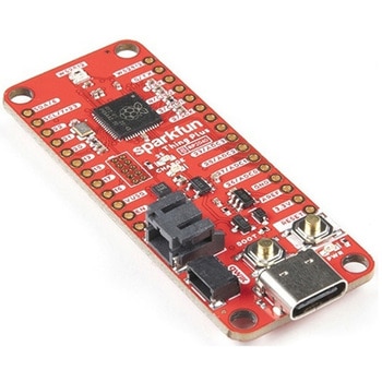
SparkFun Thing Plus - RP2040
SPARKFUN¥6,698税込¥7,3681個33日以内出荷Description。The SparkFun Thing Plus - RP2040 is a low-cost, high performance board with flexible digital interfaces featuring the Raspberry Pi Foundation's RP2040 microcontroller. Besides the Thing Plus or。Feather。footprint(with 18 GPIO pins), the board also includes an SD card slot, 16MB(128Mbit)flash memory, a JST single cell battery connector(with a charging circuit and fuel gauge sensor), an addressable WS2812 RGB LED, JTAG PTH pins, four(4-40 screw)mounting holes, and our signature Qwiic connector.。The RP2040 contains two ARM Cortex-M0+ processors(up to 133MHz)and features:264kB of embedded SRAM in six banks。6 dedicated IO for SPI Flash(supporting XIP)。30 multifunction GPIO:Dedicated hardware for commonly used peripherals。Programmable IO for extended peripheral support。Four 12-bit ADC channels with internal temperature sensor(up to 0.5 MSa/s)。USB 1.1 Host/Device functionality。The RP2040 is supported with both C/C++ and MicroPython cross-platform development environments, including easy access to runtime debugging. It has UF2 boot and floating-point routines baked into the chip. While the chip has a large amount of internal RAM, the board includes an additional 16MB of external QSPI flash memory to store program code.。The SparkFun Qwiic Connect System is an ecosystem of I2C sensors, actuators, shields and cables that make prototyping faster and less prone to error. All Qwiic-enabled boards use a common 1mm pitch, 4-pin JST connector. This reduces the amount of required PCB space, and polarized connections mean you can't hook it up wrong.。Get Started With the Thing Plus RP2040 Hookup Guide。Features。SparkFun Thing Plus - RP2040 Features。Raspberry Pi Foundation's RP2040 microcontroller。16MB QSPI Flash Memory。JTAG PTH Pins。Thing Plus(or Feather)Form-Factor:18[1]x Multifunctional GPIO Pins[2]。Four available 12-bit ADC channels with internal temperature sensor(500kSa/s)。Up to eight 2-channel PWM。Up to two UARTs。Up to two I2C buses。Up to two SPI buses。USB-C Connector:USB 1.1 Host/Device functionality。2-pin JST Connector for a LiPo Battery。(not included)。500mA charging circuit。Qwiic Connector。Buttons:Boot。Reset。LEDs:PWR。- Red 3.3V power indicator。CHG。- Yellow battery charging indicator。25。- Blue status/test LED(。GPIO 25。)。WS2812。- Addressable RGB LED(。GPIO 08。)。Four Mounting Holes:4-40 screw compatible。Dimensions:2.3"×0.9"。RP2040 General Features。Dual Cortex M0+ processors, up to 133 MHz。264 kB of embedded SRAM in 6 banks。6 dedicated IO for QSPI flash, supporting execute in place(XIP)。30 programmable IO for extended peripheral support。SWD interface。Timer with 4 alarms。Real time counter(RTC)。USB 1.1 Host/Device functionality。Supported programming languages。MicroPython。C/C++。1.。Note:。GPIO 08。is not included in this count, as it passes through the WS2812 addressable RGB LED first.。GPIO 07。and。GPIO 23。are counted as a single GPIO because they are tied together.。2.。Note:The GPIO pins are programmable so you can reconfigure the pins! Check out the RP2040 datasheet for more information on the GPIO functionality.アズワン品番67-0423-56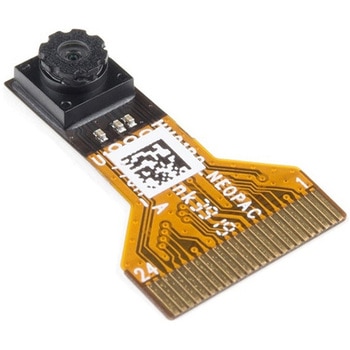
Himax CMOS Imaging Camera - HM01B0
SPARKFUN¥3,698税込¥4,0681個33日以内出荷。Description。The HM01B0 from Himax Imaging is an ultra low power CMOS Monochrome Image Sensor that enables the integration of an "Always On" camera for computer vision applications such as gestures, intelligent ambient light and proximity sensing, tracking and object identification. The sensor allows the sensor to consume very low power of <2mW at QVGA 30FPS. This low power consumption and vision applications camera comes with a ribbon cable that mates to the camera connector populated on the following products:MicroMod Machine Learning Carrier Board。Artemis Development Kit。Edge Development Board - Apollo3 Blue。The HM01B0 contains 320×320 pixel resolution and supports a 320×240 window mode which can be readout at a maximum frame rate of 60FPS, and a 2×2 monochrome binning mode with a maximum frame rate of 120FPS. The video data is transferred over a configurable 1bit, 4bit or 8bit interface with support for frame and line synchronization. The sensor integrates black level calibration circuit, automatic exposure and gain control loop, self-oscillator and motion detection circuit with interrupt output to reduce host computation and commands to the sensor to optimize the system power consumption.。Features。Image Sensor。Ultra Low Power Image Sensor(ULPIS)designed for Always On vision devices and applications。High sensitivity 3.6μ BrightSenseTM pixel technology。320×320 active pixel resolution with support for QVGA window, vertical flip and horizontal mirror readout。Programmable black level calibration target, frame size, frame rate, exposure, analog gain(up to 8x)and digital gain(up to 4x)。Automatic exposure and gain control loop with support for 50 / 60Hz flicker avoidance。Flexible 1bit, 4bit and 8bit video data interface with video frame and line sync。Motion Detection circuit with programmable ROI and detection threshold with digital output to serve as an interrupt。On-chip self oscillator。I2C 2-wire serial interface for register access。High CRA for low profile module design。Sensor Parameters。Active Pixel Array 320×320。Pixel Size 3.6 μm×3.6 μm。Full Image Area 1152 μm×1152 μm。Diagonal(Optical Format)1.63 mm(1/11″)。Scan Mode:Progressive。Shutter Type:Electronic Rolling Shutter。Frame Rate MAX 51 fps @ 320×320, 60 fps @ 320×240(QVGA)。CRA(maximum)30℃。Sensor Specifications。Supply Voltage:Analog - 2.8 V, Digital - 1.5V(Internal LDO:1.5V - 2.8V), I/O - 1.5 - 2.8V。Input Reference Clock:3 - 50 MHz。Serial Interface(I2C):2-wire, 400 KHz max.。Video Data Interface:1b, 4b, 8b with frame / line SYNC。Output Clock Rate MAX:50 MHz for 1bit, 12.5 MHz for 4bit, 6.25 MHz for 8bit。Est. Power Consumption(include IO with 5pF load):QVGA 60FPS(Typical)<4 mW。QVGA 30FPS(Typical)<2 mWアズワン品番67-0427-08