カテゴリ
- 学童・教育用品(30)
- 制御機器(2)
絞り込み
ブランド
- SPARKFUN
- HARAX(ハラックス)(240)
- 渡辺電機工業(81)
- SMC(76)
- 三菱ふそう(68)
- メディアカバーマーケット(56)
- MAXRAY(マックスレイ)(48)
- SKF(日本エスケイエフ)(47)
- VISHAY(34)
- D'Addario(33)
- SW-MOTECH (エスダブリューモテック)(31)
- NOTRAX(29)
- エレコム(24)
- アクシスコミュニケーションズ(24)
- レイ・アウト(23)
- ABRACON(22)
- ニッサン(21)
- iFace(21)
- MAD MAX(マッドマックス)(20)
- ブランドをもっと見る
「rax」の検索結果
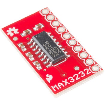
SparkFun Transceiver Breakout - MAX3232
SPARKFUN¥2,198税込¥2,4181個欠品中仕様●項目1:組込み(完成機能)●項目2:インターフェース●項目4:レベル変換●項目5:MAX3232●項目8:RS232Cトランシーバーアズワン品番67-0452-36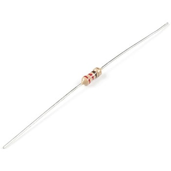
Resistor 220 Ohm 1/4th Watt PTH
SPARKFUN¥109税込¥1201個5日以内出荷Description。This is a 220 Ohm, 1/4th Watt, +/- 5% tolerance PTH resistor. Commonly used in breadboards and perf boards. We've opted for a new and more breadboard-friendly lead thickness(they're a bit thicker than our last ones).。Note:。Sold as singles.。Features。Tolerance:±5%。Power(Watts):0.25W, 1/4W。Composition:Carbon Film。Features:Flame Retardant Coating, Safety。Temperature Coefficient:0/ -400ppm/℃。Operating Temperature:-55℃ ~ 155℃。Package / Case:Axial。Size / Dimension:0.091"" Dia x 0.236"" L(2.30mm x 6.00mm)。Number of Terminations:2。Resistance:220 Ohmsアズワン品番67-0421-76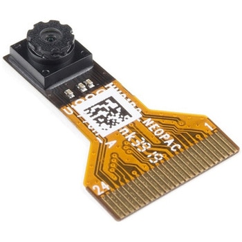
Himax CMOS Imaging Camera - HM01B0
SPARKFUN¥3,698税込¥4,0681個33日以内出荷。Description。The HM01B0 from Himax Imaging is an ultra low power CMOS Monochrome Image Sensor that enables the integration of an "Always On" camera for computer vision applications such as gestures, intelligent ambient light and proximity sensing, tracking and object identification. The sensor allows the sensor to consume very low power of <2mW at QVGA 30FPS. This low power consumption and vision applications camera comes with a ribbon cable that mates to the camera connector populated on the following products:MicroMod Machine Learning Carrier Board。Artemis Development Kit。Edge Development Board - Apollo3 Blue。The HM01B0 contains 320×320 pixel resolution and supports a 320×240 window mode which can be readout at a maximum frame rate of 60FPS, and a 2×2 monochrome binning mode with a maximum frame rate of 120FPS. The video data is transferred over a configurable 1bit, 4bit or 8bit interface with support for frame and line synchronization. The sensor integrates black level calibration circuit, automatic exposure and gain control loop, self-oscillator and motion detection circuit with interrupt output to reduce host computation and commands to the sensor to optimize the system power consumption.。Features。Image Sensor。Ultra Low Power Image Sensor(ULPIS)designed for Always On vision devices and applications。High sensitivity 3.6μ BrightSenseTM pixel technology。320×320 active pixel resolution with support for QVGA window, vertical flip and horizontal mirror readout。Programmable black level calibration target, frame size, frame rate, exposure, analog gain(up to 8x)and digital gain(up to 4x)。Automatic exposure and gain control loop with support for 50 / 60Hz flicker avoidance。Flexible 1bit, 4bit and 8bit video data interface with video frame and line sync。Motion Detection circuit with programmable ROI and detection threshold with digital output to serve as an interrupt。On-chip self oscillator。I2C 2-wire serial interface for register access。High CRA for low profile module design。Sensor Parameters。Active Pixel Array 320×320。Pixel Size 3.6 μm×3.6 μm。Full Image Area 1152 μm×1152 μm。Diagonal(Optical Format)1.63 mm(1/11″)。Scan Mode:Progressive。Shutter Type:Electronic Rolling Shutter。Frame Rate MAX 51 fps @ 320×320, 60 fps @ 320×240(QVGA)。CRA(maximum)30℃。Sensor Specifications。Supply Voltage:Analog - 2.8 V, Digital - 1.5V(Internal LDO:1.5V - 2.8V), I/O - 1.5 - 2.8V。Input Reference Clock:3 - 50 MHz。Serial Interface(I2C):2-wire, 400 KHz max.。Video Data Interface:1b, 4b, 8b with frame / line SYNC。Output Clock Rate MAX:50 MHz for 1bit, 12.5 MHz for 4bit, 6.25 MHz for 8bit。Est. Power Consumption(include IO with 5pF load):QVGA 60FPS(Typical)<4 mW。QVGA 30FPS(Typical)<2 mWアズワン品番67-0427-08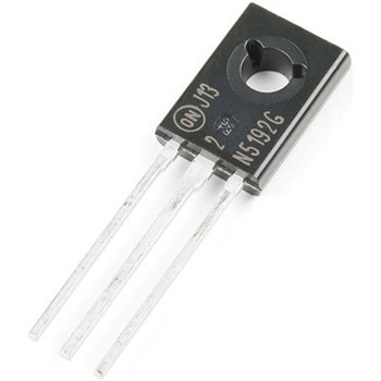
Transistor - NPN, 60V 4A 2N5192G
SPARKFUN¥379税込¥4171個33日以内出荷Description。This is the 2N5192G, an NPN silicon transistor. This little transistor can help in your project by being used to help drive large loads or amplifying or switching applications. The 2N5192G is specifically rated at 60V and 4A max.アズワン品番67-0420-88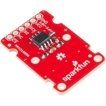
SparkFun Thermocouple Breakout - MAX31855K
SPARKFUN¥6,198税込¥6,8181個33日以内出荷Description。The SparkFun MAX31855K Thermocouple Breakout is a simple 14-bit resolution, SPI-compatible, serial interface thermocouple digitizer that makes reading a wide range of temperatures possible. A thermocouple works by taking two wires made of dissimilar metals, connecting them at the two ends, and making a temperature gradient between one end and the other(a 'hot' end and a 'cold' one). Once this is achieved, a voltage potential is formed and current flows. The SparkFun Thermocouple Breakout takes a standard Type-K thermocouple in one end, digitizes the temperature measured and sends that data out the other end via a SPI interface, thereby interpreting the data and translating it for you to read!。With the SparkFun Thermocouple Breakout, the thermocouple's hot junction can be read from -200℃ to +700℃ with an accuracy of ±2℃ while the cold junction, inside the MAX31855K, can only range from -20℃ to +85℃ while maintaining ±2℃ accuracy. The MAX31855K constantly measures the temperature of the cold junction using an internal temperature-sensing diode. The MAX31855K requires a power source from +3.0V to +3.6V(+3.0V nominal)and only draws 1.5mA maximum.。The Thermocouple Breakout is designed to accept a standard thermocouple connector, for convenience and compatibility with probes you may already own. These connectors aren't necessary, and you could solder a thermocouple directly into the through-holes labeled '+' and '-'. If you decide to solder the thermocouple directly to the breakout board, it is recommended that the thermocouple be mounted for strain relief to avoid breaking the thin wires. Notches for a zip-tie or wire wrapping have been provided in the PCB opposite the header for this purpose.。Features。14-bit Resolution。SPI-Compatible, Serial Interface。-200℃ to +700℃ Temperature Reading with ±2℃ Accuracy。3.0V to 3.6V(+3.0V nominal)Required。Accepts Type-K Thermocoupleアズワン品番67-0426-49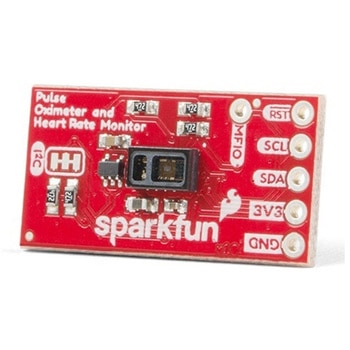
SparkFun Pulse Oximeter and Heart Rate Sensor - MAX30101 & MAX32664 Qwiic
SPARKFUN¥13,980税込¥15,3781個33日以内出荷Description。The SparkFun Pulse Oximeter and Heart Rate Sensor is an I2C based biometric sensor, utilizing two chips from Maxim Integrated:the MAX32664 Biometric Sensor Hub and the MAX30101 Pulse Oximetry and Heart Rate Module. While the latter does all the sensing, the former is an incredibly small and fast Cortex M4 processor that handles all of the algorithmic calculations, digital filtering, pressure/position compensation, advanced R-wave detection, and automatic gain control. We've provided a Qwiic connector to easily connect to the I2C data lines but you will also need to connect to two additional lines. This board is very small, measuring at 1in×0.5in(25.4mm×12.7mm), which means it will fit nicely on your finger without all the bulk.。The MAX30101 does all the sensing by utilizing its internal LEDs to bounce light off the arteries and arterioles in your finger's subcutaneous layer and sensing how much light is absorbed with its photodetectors. This is known as photoplethysmography. This data is passed onto and analyzed by the MAX32664 which applies its algorithms to determine heart rate and blood oxygen saturation(SpO2). SpO2 results are reported as the percentage of hemoglobin that is saturated with oxygen. It also provides useful information such as the sensor's confidence in its reporting as well as a handy finger detection data point. To get the most out of the sensor we've written an Arduino Library to make it easy to adjust all the possible configurations.。The SparkFun Qwiic connect system is an ecosystem of I2C sensors, actuators, shields and cables that make prototyping faster and less prone to error. All Qwiic-enabled boards use a common 1mm pitch, 4-pin JST connector. This reduces the amount of required PCB space, and polarized connections mean you can't hook it up wrong.。Get Started with the Pulse Oximeter and Heart Rate Monitor Hookup Guide。Features。SparkFun Pulse Oximeter and Heart Rate Sensor。MAX30101 and MAX32664 sensor and sensor hub。Qwiic connectors for power and I2C interface。I2C Address:0x55。MAX30101 - Pulse Oximeter and Heart-Rate Sensor。Heart-Rate Monitor and Pulse Oximeter Sensor in LED Reflective Solution。Integrated Cover Glass for Optimal, Robust Performance。Ultra-Low Power Operation for Mobile Devices。Fast Data Output Capability。Robust Motion Artifact Resilience。MAX32664 - Ultra-Low Power Biometric Sensor Hub。Biometric Sensor Hub Solution。Finger-Based Algorithms Measure Pulse Heart Rate and Pulse Blood Oxygenation Saturation(SpO2)。Both Raw and processed data are available。Basic Peripheral mix optimizes size and performanceアズワン品番67-0426-96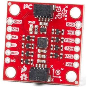
SparkFun 9DoF IMU Breakout - ICM-20948 Qwiic
SPARKFUN¥7,298税込¥8,0281個33日以内出荷。Description。The SparkFun 9DoF IMU Breakout incorporates all the amazing features of Invensense's ICM-20948 into a Qwiic-enabled breakout board complete with a logic shifter and broken out GPIO pins for all your motion sensing needs. The ICM-20948 itself is an extremely low powered, I2C and SPI enabled 9-axis motion tracking device that is ideally suited for smartphones, tablets, wearable sensors, and IoT applications. Utilizing our handy Qwiic system, no soldering is required to connect it to the rest of your system. However, we still have broken out 0.1"-spaced pins in case you prefer to use a breadboard.。In addition to the 3-Axis Gyroscope with four selectable ranges, 3-Axis Accelerometer, again with four selectable ranges, and 3-axis magnetometer with an FSR to ±4900μT, the ICM-20948 also includes a Digital Motion Processor that offloads the computation of motion sensing algorithms from the detectors, allowing optimal performance of the sensors. We've also broken out all the ICM-20948 pin functionality to GPIO and labeled them I2C on the front, SPI on the back for ease of identification.。Note:The I2C address of the ICM-20948 is 0x69 and is jumper selectable to 0x68. A multiplexer/Mux is required to communicate to multiple ICM-20948 sensors on a single bus. If you need to use more than one ICM-20948 sensor consider using the Qwiic Mux Breakout.。The SparkFun Qwiic Connect System is an ecosystem of I2C sensors, actuators, shields and cables that make prototyping faster and less prone to error. All Qwiic-enabled boards use a common 1mm pitch, 4-pin JST connector. This reduces the amount of required PCB space, and polarized connections mean you can't hook it up wrong.。Need a custom board? This component can be found in SparkFun's A La Carte board builder. You can have a custom design fabricated with this component - and your choice of hundreds of other sensors, actuators and wireless devices - delivered to you in just a few weeks.。Get Started with the SparkFun ICM-20948 9DoF IMU Guide。Features。1.95 V to 3.6 V supply voltage。Triple-axis MEMS gyroscope with user-programmable full-scale range of ±250 dps, ±500 dps, ±1000 dps, and ±2000 dps。Triple-axis MEMS accelerometer with programmable full scale range of ±2g, ±4g, ±8g, and ±16g。Triple-axis silicon monolithic Hall-effect magnetic sensor with full scale measurement range to ±4900 μT。I2C at up to 100 kHz(standard-mode)or up to 400 kHz(fast-mode)or SPI at up to 7 MHz for communicationwith registers。On-board digital motion processor(DMP)。Digital-output temperature sensor。2x Qwiic Connection Ports。I2C Address:0x69(0x68 with Jumper)。。Documents。Schematic。Eagle Files。Hookup Guide。Datasheet(ICM-20948)。Arduino Library。Python Support(Qwiic_Py)。GitHub Hardware Repoアズワン品番67-0427-05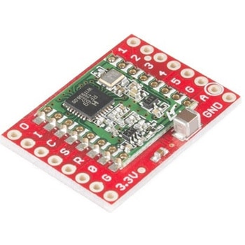
SparkFun RFM69 Breakout 434MHz
SPARKFUN¥4,398税込¥4,8381個33日以内出荷Description。This is the SparkFun RFM69 Breakout, a small piece of tech that breaks out all the pins available on the RFM69HCW module as well as making the transceiver easy to use. The RFM69HCW is an inexpensive and versatile radio module that operates in the unlicensed ISM(Industry, Science and Medicine)radio band. It's perfect for building inexpensive short-range wireless networks of sensors and actuators for home automation, citizen science and more.。This RFM69HCW operates on the 434MHz frequency and is capable of transmitting at up to 100mW and up to 300kbps, but you can change both of those values to fit your application. For example, you can maximize range by increasing the transmit power and reducing the data rate, or you can reduce both for short-range sensor networks that sip battery power. At full power and with simple wire antennas, we can get messages from one side of a large office building to the other through numerous internal walls. In open air you can reach 500 meters or more. With more complex antennas and modulation schemes, similar parts have successfully transmitted from space to the ground(by very smart amateur radio enthusiasts; your mileage may vary)!。The RFM69HCW uses an SPI(Serial Peripheral Interface)to communicate with a host microcontroller, and several good Arduino libraries are available. It supports up to 256 networks of 255 nodes per network, features AES encryption to keep your data private, and transmits data packets up to 66 bytes long.。SparkFun sells two versions of the RFM69HCW:a 915MHz version and this 434MHz version. Although the ISM band is license-free, the band itself is different in different areas. Very roughly, 915MHz is for use in the Americas, and the 434MHz version is for use in Europe, Asia and Africa. Check your local regulations for other areas.。Get Started with the RFM69HCW Hookup Guide。Features。Transmit power:-18dBm(0.016mW)to +20dBm(100mW)in 1dBm steps。Receive sensitivity:down to -120dBm at 1.2kbps。Modulation types:FSK GFSK MSK GMSK OOK。Bit rates(FSK):1.2kbps to 300kbps。Voltage range:1.8V to 3.6V。Current consumption:0.1uA sleep, 1.25mA standby, 16mA receive, 130mA transmit(max)。Encryption:AES 128-bit(optional)。Packet buffer(FIFO):66 bytes。0.8"×1.1"アズワン品番67-0429-33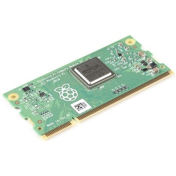
Raspberry Pi Compute Module 3+ Lite
SPARKFUN¥10,980税込¥12,0781個33日以内出荷Description。The Raspberry Pi Compute Module 3+ Lite contains the guts of a Raspberry Pi 3 Model B+(the BCM2837 processor and 1GB LPDDR2 RAM). This module allows a designer to leverage the Raspberry Pi hardware and software stack in their own custom systems and form factors. In addition this module has extra IO interfaces over and above what is available on the Raspberry Pi model A/B boards, opening up more options for the designer.。This is all integrated onto a small(67.6mm×31mm)board that fits into a standard DDR2 SODIMM connector. You get the full flexibility of the BCM2837 SoC(which means that many more GPIOs and interfaces are available than with a standard Raspberry Pi), and designing the Module into a custom system should be relatively straightforward because all the tricky bits have been put onto the Module itself.。The CM3+ Lite product is the same as CM3+ except the eMMC Flash is not fitted, and the SD/eMMC interface pins are available for the user to connect their own SD/eMMC device. Note that the CM3+ is electrically identical and, with the exception of higher CPU z-height, physically identical to the legacy CM3 products.。Note:The CM3+ modules require a software/firmware image dated November 2018 or newer to function correctly.。Features。Broadcom BCM2837B0, Cortex-A53(ARMv8)64-bit SoC @ 1.2GHz。1GB LPDDR2 SDRAM。Operating Supply Voltage:1.8V, 3.3V。Minimum Operating Temperature:-25C。Maximum Operating Temperature:+80C。HDMI, MIPI, USB, and GPIO interfaces on edge connectorアズワン品番67-0423-17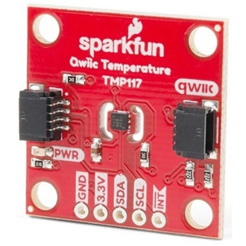
SparkFun High Precision Temperature Sensor - TMP117 Qwiic
SPARKFUN¥4,898税込¥5,3881個33日以内出荷。Description。The SparkFun Qwiic TMP117 breakout is a high precision temperature sensor equipped with an I2C interface. It outputs temperature readings with high precision of ±0.1℃ across the temperature range of -20℃ to +50℃s with no calibration and a maximum range from -55℃ to 150℃. The SparkFun High Precision Temperature Sensor also has a very low power consumption rate which minimizes the impact of self-heating on measurement accuracy. Utilizing our handy Qwiic system, no soldering is required to connect it to the rest of your system. However, we still have broken out 0.1"-spaced pins in case you prefer to use a breadboard.。The SparkFun High Precision Temperature Sensor also includes programmable temperature limits, and digital offset for system correction. While the TMP102 is capable of reading temperatures to a resolution of 0.0625℃ and is accurate up to 0.5℃, the on-board TMP117 is not only more precise but has a 16-bit resolution of 0.0078℃!。To make this breakout even easier to use, we've written an Arduino library to help you get started "Qwiic-ly." Check the Documents tab above for more information.。The SparkFun Qwiic Connect System is an ecosystem of I2C sensors, actuators, shields and cables that make prototyping faster and less prone to error. All Qwiic-enabled boards use a common 1mm pitch, 4-pin JST connector. This reduces the amount of required PCB space, and polarized connections mean you can't hook it up wrong.。The TMP117 High Precision Temperature Sensor can also be automatically detected, scanned, configured, and logged using the OpenLog Artemis datalogger system. No programming, soldering, or setup required!。Need a custom board? This component can be found in SparkFun's A La Carte board builder. You can have a custom design fabricated with this component - and your choice of hundreds of other sensors, actuators and wireless devices - delivered to you in just a few weeks.。Get Started with the SparkFun High Precision TMP117 Hookup Guide。Features。Uses I2C interface(Qwiic-enabled)。Four selectable addresses。0x48(default), 0x49, 0x4A, 0x4B。16-bit resolution, 0.0078℃。High accuracy, digital temperature sensor。±0.1℃(max)from ?20℃ to 50℃。±0.15℃(max)from ?40℃ to 70℃。±0.2℃(max)from ?40℃ to 100℃。±0.25℃(max)from ?55℃ to 125℃。±0.3℃(max)from ?55℃ to 150℃。Operating temperature range。-55℃ to +150℃。Operating voltage range。1.8V to 5.5V。Typically 3.3V if using the Qwiic cable。Low power consumption。3.5μA(1-Hz conversion cycle)。150nA(shutdown current)。Programmable operating modes。Continuous, one-shot, and shutdown。Programmable temperature alert limits。Selectable averaging for reduced noise。Digital offset for system correction。NIST traceability。。Documents。Schematic。Eagle Files。Board Dimensions。Hookup Guide。Datasheet(TMP117)。Arduino Library。GitHub Hardware Repoアズワン品番67-0427-10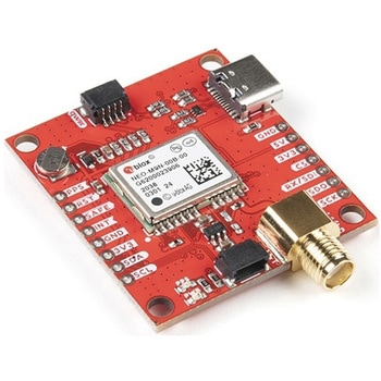
SparkFun GPS Breakout - NEO-M9N, SMA Qwiic
SPARKFUN¥22,980税込¥25,2781個33日以内出荷Description。The SparkFun NEO-M9N GPS Breakout is a high quality GPS board with equally impressive configuration options including SMA. The NEO-M9N module is a 92-channel u-blox M9 engine GNSS receiver, meaning it can receive signals from the GPS, GLONASS, Galileo, and BeiDou constellations with ~1.5 meter accuracy. This breakout supports concurrent reception of four GNSS. This maximizes position accuracy in challenging conditions increasing, precision and decreases lock time; and thanks to the onboard rechargeable battery, you'll have backup power enabling the GPS to get a hot lock within seconds! Additionally, this u-blox receiver supports I2C(u-blox calls this Display Data Channel)which makes it perfect for the Qwiic compatibility so we don't have to use up our precious UART ports. Utilizing our handy Qwiic system, no soldering is required to connect it to the rest of your system. However, we still have broken out 0.1"-spaced pins in case you prefer to use a breadboard.。The NEO-M9N module detects jamming and spoofing events and can report them to the host, so that the system can react to such events. A SAW(Surface Acoustic Wave)filter combined with an LNA(Low Noise Amplifier)in the RF path is integrated into the NEO-M9N module which allows normal operation even under strong RF interferences.。U-blox based GPS products are configurable using the popular, but dense, windows program called u-center. Plenty of different functions can be configured on the NEO-M9N:baud rates, update rates, geofencing, spoofing detection, external interrupts, SBAS/D-GPS, etc. All of this can be done within the SparkFun Arduino Library!。The SparkFun NEO-M9N GPS Breakout is also equipped with an on-board rechargeable battery that provides power to the RTC on the NEO-M9N. This reduces the time-to-first fix from a cold start(~24s)to a hot start(~2s). The battery will maintain RTC and GNSS orbit data without being connected to power for plenty of time.。This product requires an antenna:Be sure to check out the related products/hookup accessories and pick a suitable SMA antenna for your project.。The SparkFun Qwiic Connect System is an ecosystem of I2C sensors, actuators, shields and cables that make prototyping faster and less prone to error. All Qwiic-enabled boards use a common 1mm pitch, 4-pin JST connector. This reduces the amount of required PCB space, and polarized connections mean you can't hook it up wrong.。The NEO-M9N GPS Breakout can also be automatically detected, scanned, configured, and logged using the OpenLog Artemis datalogger system. No programming, soldering, or setup required!。Get Started With the SparkFun NEO-M9N GPS Guide。Features。Integrated SMA connector for use with antenna of your choice。92-Channel GNSS Receiver。1.5m Horizontal Accuracy。25Hz Max Update Rate(four concurrent GNSS)。Time-To-First-Fix:Cold:24s。Hot:2s。Max Altitude:80,000m。Max G:≦4。Max Velocity:500m/s。Velocity Accuracy:0.05m/s。Heading Accuracy:0.3 degrees。Time Pulse Accuracy:30ns。3.3V VCC and I/O。Current Consumption:~31mA Tracking GPS+GLONASS。Software Configurable。Geofencing。Odometer。Spoofing Detection。External Interrupt。Pin Control。Low Power Mode。Many others!。Supports NMEA, UBX, and RTCM protocols over UART or I2C interfacesアズワン品番67-0423-87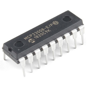
I/O Expander - MCP23008
SPARKFUN¥639税込¥7031個33日以内出荷。Description。Add another eight pins to your microcontroller using a MCP23008 port expander. The MCP23008 uses two I2C pins which can be shared with other I2C devices, and in exchange gives you eight general purpose pins. You can set each of eight pins to be input, output, or input with a pullup. There's even the ability to get an interrupt via an external pin when any of the inputs change so you don't have to keep polling the chip.。Use this chip from 2.7-5.5V(good for any 3.3V or 5V setup), and you can sink/source up to 20mA from any of the I/O pins so this will work for LEDs and such. Team it up with a high-power MOSFET if you need more juice. DIP package means it will plug into any breadboard or perfboard.。You can set the I2C address by tying the ADDR0-2 pins to power or ground, for up to eight unique addresses. That means eight chips can share a single I2C bus - that's 64 I/O pins!。Features。8-bit remote bidirectional I/O port。High-speed I2C interface(MCP23008)。Hardware address pins。Configurable interrupt output pin。Configurable interrupt source。Polarity Inversion register for input port data polarity config.。External reset input。Low standby current:1 μA(max.)・ Operating voltage:。1.8V to 5.5V @ -40℃ to +85℃ I2C @ 100 kHz SPI @ 5 MHz。2.7V to 5.5V @ -40℃ to +85℃ I2C @ 400 kHz SPI @ 10 MHz。4.5V to 5.5V @ -40℃ to +125℃ I2C @ 1.7 kHz SPI @ 10 MHzアズワン品番67-0421-32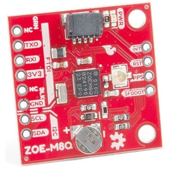
SparkFun GPS Breakout - ZOE-M8Q Qwiic
SPARKFUN¥14,980税込¥16,4781個33日以内出荷Description。The SparkFun ZOE-M8Q GPS Breakout is a high accuracy, miniaturized, GPS board that is perfect for applications that don't possess a lot of space. The on-board ZOE-M8Q is a 72-channel GNSS receiver, meaning it can receive signals from the GPS, GLONASS, BeiDou, and Galileo constellations. This increases precision and decreases lock time and thanks to the onboard rechargable battery you'll have backup power enabling the GPS to get a hot lock within seconds! Additionally, this u-blox receiver supports I2C(u-blox calls this Display Data Channel)which made it perfect for the Qwiic compatibility so we don't have to use up our precious UART ports. Utilizing our handy Qwiic system, no soldering is required to connect it to the rest of your system. However, we still have broken out 0.1"-spaced pins in case you prefer to use a breadboard.。U-blox based GPS products are configurable using the popular, but dense, windows program called u-center. Plenty of different functions can be configured on the ZOE-M8Q:baud rates, update rates, geofencing, spoofing detection, external interrupts, SBAS/D-GPS, etc. All of this can be done within the SparkFun Arduino Library. We've also made sure to configure the UART pin grouping on the breakout to an industry standard to insure that it easily connects to a Serial Basic.。The SparkFun ZOE-M8Q GPS Breakout is also equipped with an on-board rechargeable battery that provides power to the RTC on the ZOE-M8Q. This reduces the time-to-first fix from a cold start(~30s)to a hot start(~1s). The battery will maintain RTC and GNSS orbit data without being connected to power for up to five hours. Since the ZOE-M8Q is a tiny GPS receiver and to minimize its footprint, we've added a U.FL connector to allow the use of both large standard ceramic antennas as well as very small chip scale antennas.。Note:The I2C address of the ZOE-M8Q is 0x42 and is software configurable. A multiplexer/Mux is required to communicate to multiple ZOE-M8Q sensors on a single bus. If you need to use more than one ZOE-M8Q sensor consider using the Qwiic Mux Breakout.。The SparkFun Qwiic Connect System is an ecosystem of I2C sensors, actuators, shields and cables that make prototyping faster and less prone to error. All Qwiic-enabled boards use a common 1mm pitch, 4-pin JST connector. This reduces the amount of required PCB space, and polarized connections mean you can't hook it up wrong.。The ZOE-M8Q GPS Breakout can also be automatically detected, scanned, configured, and logged using the OpenLog Artemis datalogger system. No programming, soldering, or setup required!。Get Started With the SparkFun ZOE-M8Q Hookup Guide。Features。72-Channel GNSS Receiver。2.5m Horizontal Accuracy。18Hz Max Update Rate。Time-To-First-Fix:Cold:26s。Hot:1s。Max Altitude:50,000m。Max G:≦4。Max Velocity:500m/s。Velocity Accuracy:0.05m/s。Heading Accuracy:0.3 degrees。Time Pulse Accuracy:30ns。3.3V VCC and I/O。Current Consumption:~29mA Tracking GPS+GLONASS。Software Configurable。Geofencing。Odometer。Spoofing Detection。External Interrupt。Pin Control。Low Power Mode。Many others!。Supports NMEA, UBX, and RTCM protocols over UART or I2C interfacesアズワン品番67-0423-76
Actuonix PQ12-100-6-R Micro-Actuator
SPARKFUN¥47,980税込¥52,7781個33日以内出荷Description。The PQ12 series of micro linear actuators are ideal for applications requiring precise positioning and compact size. Weighing in at just 22 grams, the PQ12 is incredibly light as well as compact. The affordably-priced PQ12 is the most powerful actuator of it's size. This is why it has become a popular choice for OEM manufacturers as well as Arduino and RC hobbyists. Some industries where the PQ12 are in use include:prosthetics, robotics, medical, simulation.。The PQ12-R series of linear servos operate as a direct replacement for standard rotary servos. They use the same standard 3 wire connector, ground power and control. Regardless of how you drive your servos, be it with an RC receiver, an Arduino board, or a VEX micro-controller, the PQ12-R servo will function in place of a regular servo, but with the added benefit of providing linear motion. The PQ12-R is available in a 20mm stroke coupled with gear ratio options of 30:1, 63:1 and 100:1 cover a large variety of applications.。The PQ12-100-6-R has:a 100:1 gear ratio for maximum lifting force; 6VDC operating voltage; and a servo(PWM)interface. This powerful little actuator can lift 50N(~5kg)!。The datasheet doesn't mention a minimum operating voltage, but we've tested this actuator at 5VDC and it seems to work just fine. The maximum force and movement speed are reduced of course.。Features。Gearing Option:100:1。Peak Power Point:40N @ 6mm/s。Peak Efficiency Point:20N @ 8mm/s。Max Speed(no load):10mm/s。Max Force(lifted):50N。Max Side Load:10N。Back Drive Force:35N。Stroke:20 mm。Input Voltage:6 VDC。Stall Current:550mA @ 6V。Mass:22g。Operating Temperature -10℃ to +50℃。Positional Repeatability:±0.1mm。Mechanical Backlash:0.25 mm。Audible Noise:55dB @ 45cm。Ingress Protection:IP-54。Maximum Duty Cycle:20%。PWM(Servo)signal:Fully retracted:2.0ms @ 50Hz。Fully extended:1.0ms @ 50Hzアズワン品番67-0426-44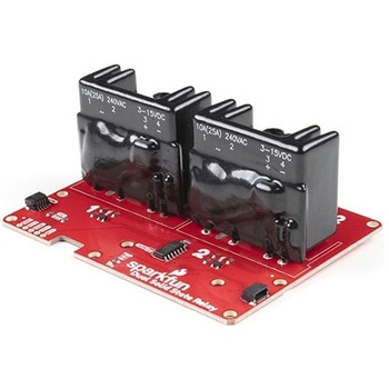
SparkFun Qwiic Dual Solid State Relay
SPARKFUN¥39,980税込¥43,9781個33日以内出荷Description。The SparkFun Qwiic Dual Solid State Relay is a power delivery board that allows users to switch two AC loads from a low power microcontroller using the SparkFun Qwiic connect system. The board features two 25A/250VAC solid state relays that utilize the Zero Cross Trigger method so you can toggle two loads on a 60Hz AC carrier signal on and off up to 120 times per second!。An ATTiny84 acts as the "brain" of the SparkFun Qwiic Dual Solid Relay to accept I2C commands to toggle the two relays as well as a few other special commands. The I2C address of the ATtiny84A is software configurable so, if you have a seriously big power project in mind, you could daisy chain over 100 Qwiic Dual Solid State Relays.。Messing with such high voltage is dangerous! We've included many safety precautions onto the PCB including ground isolation between the relay and other circuitry and a milled out area isolating each side of AC. However, with all the safety precautions included with the SparkFun Qwiic Dual Solid State Relay, this is still a power accessory for users who are experienced around, and knowledgeable about high AC voltage. If you're not comfortable with handling AC voltage in this way, you may want to check out the IoT Power Relay instead.。Note:The relays are rated for a max of 25A with forced air cooling. If you do not have forced air cooling, 10A max through the relays is recommended.。The SparkFun Qwiic connect system is an ecosystem of I2C sensors, actuators, shields and cables that make prototyping faster and less prone to error. All Qwiic-enabled boards use a common 1mm pitch, 4-pin JST connector. This reduces the amount of required PCB space, and polarized connections mean you can't hook it up wrong.。Get Started with the SparkFun Qwiic Dual Solid State Relay Guide。Features。Operating Voltage:2.5-3.6V(3.3V recommended)。I2C Address:0x0A(Default)0x0B(Alternate via jumper select)。Load Voltage Range:12-280VAC。Max Current(Through Relay):25A(240VAC with forced air cooling)。Zero Cross Trigger。Normally Open Circuit Only。2x Qwiic Connectorアズワン品番67-0421-58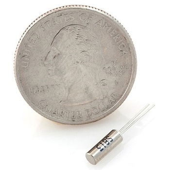
Crystal 32kHz
SPARKFUN¥579税込¥6371個33日以内出荷Description。Standard 'Watch' or Real-Time-Clock crystal. 32.768kHz means it is precisely half of a 16-bit counter. Start counting at 0x8000(or 32768). When the counter rolls over from 65535 to 0, then you know that exactly one second has passed. Reset the interrupt, reset the counter, and start counting again! Rated at 12.5pF load capacitance, 35K ohm max(18K ohm typical)series resistance, and +/- 20ppm stability. Small cylinder package.アズワン品番67-0429-94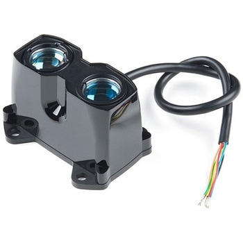
LIDAR-Lite v3HP
SPARKFUN¥49,980税込¥54,9781個33日以内出荷Description。LIDAR has never looked so good! This is the LIDAR-Lite v3HP, a compact, high-performance optical distance measurement sensor from Garmin(TM). The LIDAR-Lite v3HP is。the。ideal optical ranging solution for drone, robot, or unmanned vehicle applications. Each sensor is housed in a durable, IPX7-rated housing and includes all the core features and user configurability of the popular LIDAR-Lite v3.。The v3HP is very similar in function to that of the v3 but it can now sample faster at rates greater than 1kHz(where as the v3 is only capable of up to 500Hz). Another improvement is that this v3HP model is more power efficient with current consumption rates 40mA less than the v3(that's 65mA as opposed to 105mA while idle, and 85mA instead of 130mA while acquiring).。Each LIDAR-Lite v3HP has a range of 1m to 40m and features an edge-emitting, 905nm(1.3 watts), single-stripe laser transmitter, 8m Radian beam divergence, and an optical aperture of 12.5mm. This version of the LIDAR-Lite still operates at 5VDC(6V max)with a peak power of 1.3W and still possesses an accuracy of +/- 2.5cm at >2m. On top of everything else, the LIDAR-Lite is user-configurable, allowing adjustment between accuracy, operating range and measurement time and can be interfaced via I2C or PWM with the attached 200mm cable.。Note:CLASS 1 LASER PRODUCT CLASSIFIED EN/IEC 60825-1 2014. This product is in conformity with performance standards for laser products under 21 CFR 1040, except with respect to those characteristics authorized by Variance Number FDA-2016-V-2943 effective September 27, 2016.。Get Started with the LIDAR-Lite v3HP Guide。Features。Resolution:1 cm。Typical accuracy:+/- 2.5cm at distances greater than 2 meters(Refer to operating manual for complete operating specifications)。Range:1m to 40m。Update rate:Greater than 1kHz。Interface:I2C or PWM。Power(operating voltage):4.75-5VDC; 6V Max。Current consumption:65ma idle; 85ma during acquisition。Operating temperature:-20℃ to 60℃。Laser wave length/Peak power:905nm/1.3W。Beam divergence:8m Radian。Optical aperture:12.5mm。Water rating:IPX7。Unit dimensions:24.5mm×53.5mm×33.5mm(1.0in×2.1in×1.3in)。Weight:34g(1.2oz)アズワン品番67-0426-76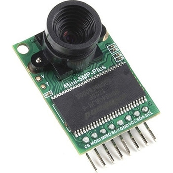
Arducam 5MP Plus OV5642 Mini Camera Module
SPARKFUN¥23,980税込¥26,3781個33日以内出荷Description。The Arducam 5MP Plus OV5642 Mini provides an easy to use camera solution for those working with low-cost microcontrollers such as those used with Arduino and the RP2040 from Raspberry Pi. It's a general purpose 5MP camera module that's SPI enabled reducing the complexity of controlling the camera. It's a step up in performance from it's predecessor, the Arducam-M-5MP. The most impressive aspect being that it's possible to control more than one of these from the same microcontroller. It features a M12 mount or CS-Mount lens holder with the ability to change lenses. Best of all, there's code libraries for Arduino, STM32, Chipkit, Raspberry Pi, and BeagleBone Black.。The Arducam 5MP Plus OV5642 Mini supports JPEG compression mode, single and multiple shoot mode, short movie recording, one-time capture multiple read operation, burst read operation, and low power mode.。Features。Power supply 3.3V~5V。Active array size:2592×1944。SPI speed:Max 8MHz。Shutter:rolling shutter。Frame buffer:8MByte。Pixel Size:1.4μm×1.4μm。Default M12 Lens:55°。Resolution support:5MP, 1080p, 720p, VGA, QVGA。Format support:RAW, YUV, RGB, JPEG。Size:34×24 mm。Weight:20g。Temperature Range:-10℃~+55℃。Lens Specification:sensor size:1/4″; EFL:4.9mm; F/N:2.2; BFL:1.2mm; HFOV:60 degree(SKU:U6067)アズワン品番67-0423-65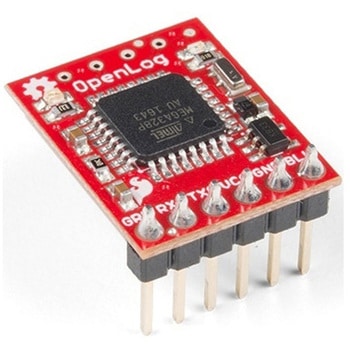
SparkFun OpenLog with Headers
SPARKFUN¥6,898税込¥7,5881個33日以内出荷Description。The SparkFun OpenLog with Headers is an open source data logger that works over a simple serial connection and supports microSD cards up to 64GB. The OpenLog can store or "log" huge amounts of serial data and act as a black box of sorts to store all the serial data that your project generates, for scientific or debugging purposes. This version of th OpenLog even includes pre-soldered headers for your convenience.。The SparkFun OpenLog uses an ATmega328 running at 16MHz thanks to the onboard resonator. The OpenLog draws approximately 2-3mA in idle(nothing to record)mode. During a full record OpenLog can draw 10 to 20mA depending on the microSD card being used.。All data logged by the OpenLog is stored on the microSD card. Any 512MB to 32GB microSD card should work. OpenLog supports both FAT16 and FAT32 SD formats.。For even better performance the OpenLog Artemis is the tool you need, featuring logging speeds up to 500000bps.。Get Started with the SparkFun OpenLog Guide。Features。VCC Input:3.3V-12V(Recommended 3.3V-5V)。Log to low-cost microSD FAT16/32 cards up to 32GB。Simple command interface。Configurable baud rates(up to 115200bps)。Preprogrammed ATmega328 and bootloader。Four SPI pogo pins。Two LEDs indicate writing status。2mA idle, 6mA at maximum recording rate。Pre-soldered Headersアズワン品番67-0422-30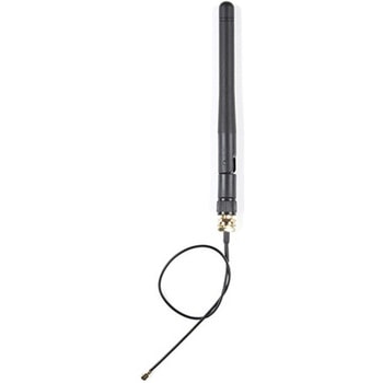
Raspberry Pi 4 Compute Module Antenna Kit
SPARKFUN¥5,598税込¥6,1581個33日以内出荷Description。This is the Antenna Kit for the Raspberry Pi 4 Compute Module wireless variants. The "duck" style antenna adds range to the wireless radio on the wireless enabled Compute Modules. Something quite desirable if you're working in industrial environments or other places a Compute Module would be used and the potential for signal interference is present. The antenna connects to the board via the press-fit U.FL connector on board the compute module(see photos for more details).。This kit contains an antenna, bulkhead fixture, and SMA to U.FL Cable.。Features。Frequency range:2400-2500/5100-5800 MHz。Bandwidth:100-700MHz。VSWR:≦ 2.0。Gain:2 dBi。Impedance:50 ohm。Polarisation:Vertical。Radiation:Omnidirectional。Maximum power:10W。Antenna dimensions:108 mm×10 mmアズワン品番67-0429-69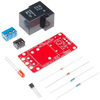
SparkFun Beefcake Relay Control Kit Ver. 2.0
SPARKFUN¥3,198税込¥3,5181個33日以内出荷Description。Your 5V system can wield great power with this big, beefy relay board. How does 10A on the NC contacts and 20A on the NO contacts at 220VAC sound? The SparkFun Beefcake Relay Control Kit contains all the parts you need to get your high-power load under control. Only minimal assembly is required!。The heart of the board is sealed, SPDT 20A/10A Relay. The relay is controlled by 5V logic through transistor, and an LED tells you when the relay is closed. This is kit, so it comes as through-hole parts with assembly required, which makes for some nice soldering practice. Screw terminal connectors on either side of the board make it easy to incorporate into your project.。There are some pretty beefy traces connecting the relay to the load pins, but the 3-pin terminals are only rated for 15A max! If you plan on connecting larger load, you'll need to solder directly to the board. As always with high current and voltage, play it safe and use your judgment when deciding how much of load you want to put on board -- in open airflow the PCB can handle the full 20A for few minutes at time, but in an enclosed area heat can build up.。Note:Please keep in mind that this board is really meant for someone with experience and good knowledge of electricity. If you're uncomfortable soldering or dealing with high voltage, please check out the IoT Power Relay. The IoT Power Relay is fully enclosed, making it lot safer.。Get Started With the Beefcake Hookup Assembly Guide。Features。Voltage Rating:220VAC/28VDC。VCC requirements:4-6V, 150mA capable。SPDT pins exposed(Form C)。14 AWG screw terminals for relay connections.。10 AWG solder lugs for relay connections.。Flyback diode included。Zener recovery diode included(decreases turn-off time)。Heavy oz. copper on PCBアズワン品番67-0424-03
SparkFun Qwiic Alphanumeric Display - COMシリーズ
SPARKFUN¥2,998税込¥3,2981個33日以内出荷Description。The SparkFun Alphanumeric Display Arduino library makes printing strings to the display as easy as calling the print()function. With this library, you'll be able to send I2C commands to the VK16K33 LED driver chip to light up segments(including the decimal point or colon)and even scroll your string across the display. You can download the library through the Arduino library manager by searching 'SparkFun Alphanumeric Display' or you can get the GitHub repo as a .zip file and install the library from there.。The SparkFun Qwiic Connect System is an ecosystem of I2C sensors, actuators, shields and cables that make prototyping faster and less prone to error. All Qwiic-enabled boards use a common 1mm pitch, 4-pin JST connector. This reduces the amount of required PCB space, and polarized connections mean you can't hook it up wrong.。Get Started with the Qwiic Alphanumeric Display Hookup Guide。Features。Operating Voltage:3.3V。Integrated RC oscillator。Maximum display segment numbers:128 patterns。13×3 matrix key scan circuit。16-step dimming circuit。I2C Addresses:0x70(0x71, 0x72, 0x73)。2x Qwiic connectors。2x Wall Mounting Pointsアズワン品番67-0421-61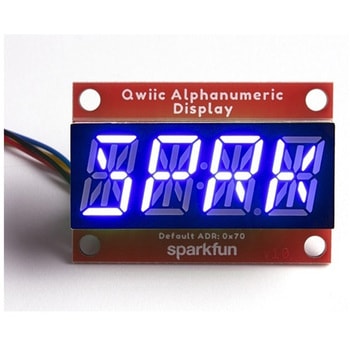
SparkFun Qwiic Alphanumeric Display - COMシリーズ
SPARKFUN¥2,998税込¥3,2981個33日以内出荷Description。The SparkFun Alphanumeric Display Arduino library makes printing strings to the display as easy as calling the print()function. With this library, you'll be able to send I2C commands to the VK16K33 LED driver chip to light up segments(including the decimal point or colon)and even scroll your string across the display. You can download the library through the Arduino library manager by searching 'SparkFun Alphanumeric Display' or you can get the GitHub repo as a .zip file and install the library from there.。The SparkFun Qwiic Connect System is an ecosystem of I2C sensors, actuators, shields and cables that make prototyping faster and less prone to error. All Qwiic-enabled boards use a common 1mm pitch, 4-pin JST connector. This reduces the amount of required PCB space, and polarized connections mean you can't hook it up wrong.。Get Started with the Qwiic Alphanumeric Display Hookup Guide。Features。Operating Voltage:3.3V。Integrated RC oscillator。Maximum display segment numbers:128 patterns。13×3 matrix key scan circuit。16-step dimming circuit。I2C Addresses:0x70(0x71, 0x72, 0x73)。2x Qwiic connectors。2x Wall Mounting Pointsアズワン品番67-0421-62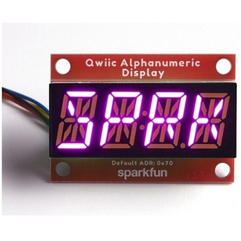
SparkFun Qwiic Alphanumeric Display - COMシリーズ
SPARKFUN¥3,198税込¥3,5181個33日以内出荷Description。The SparkFun Alphanumeric Display Arduino library makes printing strings to the display as easy as calling the print()function. With this library, you'll be able to send I2C commands to the VK16K33 LED driver chip to light up segments(including the decimal point or colon)and even scroll your string across the display. You can download the library through the Arduino library manager by searching 'SparkFun Alphanumeric Display' or you can get the GitHub repo as a .zip file and install the library from there.。The SparkFun Qwiic Connect System is an ecosystem of I2C sensors, actuators, shields and cables that make prototyping faster and less prone to error. All Qwiic-enabled boards use a common 1mm pitch, 4-pin JST connector. This reduces the amount of required PCB space, and polarized connections mean you can't hook it up wrong.。Get Started with the Qwiic Alphanumeric Display Hookup Guide。Features。Operating Voltage:3.3V。Integrated RC oscillator。Maximum display segment numbers:128 patterns。13×3 matrix key scan circuit。16-step dimming circuit。I2C Addresses:0x70(0x71, 0x72, 0x73)。2x Qwiic connectors。2x Wall Mounting Pointsアズワン品番67-0421-64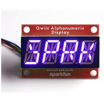
SparkFun Qwiic Alphanumeric Display - COMシリーズ
SPARKFUN¥2,998税込¥3,2981個33日以内出荷Description。The SparkFun Alphanumeric Display Arduino library makes printing strings to the display as easy as calling the print()function. With this library, you'll be able to send I2C commands to the VK16K33 LED driver chip to light up segments(including the decimal point or colon)and even scroll your string across the display. You can download the library through the Arduino library manager by searching 'SparkFun Alphanumeric Display' or you can get the GitHub repo as a .zip file and install the library from there.。The SparkFun Qwiic Connect System is an ecosystem of I2C sensors, actuators, shields and cables that make prototyping faster and less prone to error. All Qwiic-enabled boards use a common 1mm pitch, 4-pin JST connector. This reduces the amount of required PCB space, and polarized connections mean you can't hook it up wrong.。Get Started with the Qwiic Alphanumeric Display Hookup Guide。Features。Operating Voltage:3.3V。Integrated RC oscillator。Maximum display segment numbers:128 patterns。13×3 matrix key scan circuit。16-step dimming circuit。I2C Addresses:0x70(0x71, 0x72, 0x73)。2x Qwiic connectors。2x Wall Mounting Pointsアズワン品番67-0421-63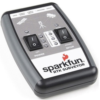
SparkFun RTK Surveyor
SPARKFUN¥129,800税込¥142,7801個33日以内出荷Description。The SparkFun RTK Surveyor is an easy to use GNSS receiver for centimeter-level positioning. Perfect for surveying, this preprogrammed device can also be used for autonomous driving, navigation, asset tracking and any other application where there is a clear view of the sky. The RTK Surveyor can also be used as a base station. With the flick of a switch, two RTK Surveyors can be used to create an RTK system capable of 14mm horizontal positional accuracy. The built-in Bluetooth(R)connection via an ESP32 WROOM enables the user to use the RTK Surveyor with their choice of GIS application on a phone or tablet. The built in battery allows field use for up to four hours and is compatible with common USB battery banks.。This device can be used in four modes:GNSS Positioning(~30cm accuracy)。GNSS Positioning with RTK(1.4cm accuracy)。GNSS Base Station。GNSS Base Station NTRIP Server。In Position mode the device receives L1/L2 signals from a user-provided antenna and the high-grade GNSS receiver provides lat/long and altitude with accuracies around 300mm.。In Positioning with RTK mode the device receives L1/L2 signals from the antenna and correction data from a base station. The correction data can be obtained from a cellular link to online correction sources or over a radio link to a 2nd RTK Surveyor setup as a base station.。In Base Station mode the device is mounted to a temporary position(like a tripod)and begins transmitting correction data over a radio or internet connection. A base is often used in conjunction with a second unit set to 'Positioning with RTK' to obtain the 14mm relative accuracy.。In Base Station NTRIP Server mode the device is mounted to a semi or permanently fixed position(like a roof)and connects over WiFi to transmit the correction data to a NTRIP caster so that any rover can access the correction data over a cellular or internet connection. This type of base is a very easy way to setup a very precise absolute correction source.。Two cables are provided with the RTK Surveyor allowing a user to plug on our easy to use Serial Telemetry Radios or their own radio link. If a local correction source is within 10km, a user can also use their phone to provide correction data over the Bluetooth(R)link(no external radio needed!).。Note:The SparkFun RTK Surveyor is just the enclosed device and does NOT include an antenna, serial telemetry radio, or associated mounting pieces. These items will need to be purchased separately from the Hookup Accessories below.。Get Started With the SparkFun RTK Surveyor Guide。Features。GNSS Receiver:ZED-F9P。Concurrent reception of GPS, GLONASS, Galileo and BeiDou。Receives both L1C/A and L2C bands。Current:68mA - 130mA(varies with constellations and tracking state)。Time to First Fix:25s(cold), 2s(hot)。Max Navigation Rate:PVT(basic location over UBX binary protocol)- 25Hz。RTK - 20Hz。Raw - 25Hz。Horizontal Position Accuracy:2.5m without RTK。0.010m with RTK。Max Altitude:50km(31 miles)。Max Velocity:500m/s(1118mph)。Bluetooth(R)Transceiver:ESP32 WROOM。Xtensa(R)dual-core 32-bit LX6 microprocessor。Up to 240MHz clock frequency。16MB of flash storage。520kB internal SRAM。Integrated 802.11 BGN WiFi transceiver。Integrated dual-mode Bluetooth(R)(classic and BLE)。Hardware accelerated encryption(AES, SHA2, ECC, RSA-4096)。2.5 μA deep sleep current。Overall Device。Internal Battery:LiPo 1000mAh with 500mA charging。Radio Port:3.3V TTL Serial(57600bps RTCM TX/RX)。Data Port:3.3V TTL Serial(115200bps NMEA)。Weight:132g(entire device including battery)。Dimensions:118mm×79mm×30mm(4.7in×3.1in×1.2in)。1x Qwiic Connector。1x microSD Socket for optional logging。Changes:This version(which replaces SPX-17369)uses a reinforced edge mount SMA connector for better resiliency when a fixed 'stub' antenna is used.アズワン品番67-0423-95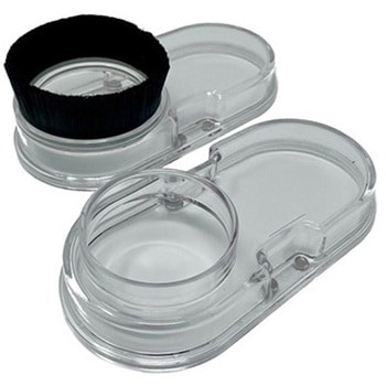
Sweepy 2.0 69mm
SPARKFUN¥20,980税込¥23,0781個33日以内出荷Description。Sweepy 2.0 is our new Dust Boot made from clear polycarbonate.。Version 2.0 features a number of enhancements, that stem from customer feedback. These include:Sweepy 65 V2 - now can now travel up and down the spindle body allowing greater flexibility when milling。Now fits a 2.5" Shopvac as standard。Includes adapters for:2.5" direct hose。2.25" shop vac。36mm Festool/Fein。Includes our affectionally-named "Winston" a clear brush free base for 3d carving and video making。This 69mm size is for the Dewalt spindles.。Sweepy mounts directly to your spindle and is clamped with a machined quick-release. The compact design means that no travel is lost, and it works with any Shapeoko Z-axis with no adapters. The lower half is detachable and held in place using neodymium magnets, which means that the top half remains in place while the lower half detaches for easy access when changing bits.。(For the legal sticklers out there, the Shapeoko and Compact Router shown in the photos are not included with Sweepy.)アズワン品番67-0429-12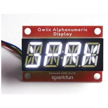
SparkFun Qwiic Alphanumeric Display - White
SPARKFUN¥2,998税込¥3,2981個33日以内出荷Description。We are quite familiar with seven-segment displays. We see them on our alarm clocks, ovens, and microwaves. By adding more segments to each digit you can display more than just numbers! Introducing the brand new SparkFun Qwiic Alphanumeric Display. These white fourteen-segment digits allow you display all sorts of numbers, characters, and symbols. With Qwiic, simply plug it in and go. No soldering, no figuring out which is SDA or SCL, and no voltage regulation or translation required!。The SparkFun Alphanumeric Display Arduino library makes printing strings to the display as easy as calling the print()function. With this library, you'll be able to send I2C commands to the VK16K33 LED driver chip to light up segments(including the decimal point or colon)and even scroll your string across the display. You can download the library through the Arduino library manager by searching 'SparkFun Alphanumeric Display' or you can get the GitHub repo as a .zip file and install the library from there.。The VK16K33 also supports I2C address configuration. Simply close a combination of the address jumpers on the back and you can communicate with up to four displays on the same bus. Our slim board design also features detachable stand off holes, vertical Qwiic connectors, and internal mounting holes.。The SparkFun Qwiic Connect System is an ecosystem of I2C sensors, actuators, shields and cables that make prototyping faster and less prone to error. All Qwiic-enabled boards use a common 1mm pitch, 4-pin JST connector. This reduces the amount of required PCB space, and polarized connections mean you can't hook it up wrong.。Get Started with the Qwiic Alphanumeric Display Hookup Guide。Features。White display。Operating Voltage:3.3V。Integrated RC oscillator。Maximum display segment numbers:128 patterns。13×3 matrix key scan circuit。16-step dimming circuit。I2C Addresses:0x70(0x71, 0x72, 0x73)。2x Qwiic connectors。2x Wall Mounting Pointsアズワン品番67-0421-87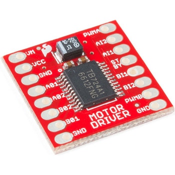
モータードライバ
SPARKFUN¥4,798税込¥5,2781個33日以内出荷Description。The TB6612FNG Motor Driver can control up to two DC motors at a constant current of 1.2A(3.2A peak). Two input signals(IN1 and IN2)can be used to control the motor in one of four function modes:CW, CCW, short-brake and stop. The two motor outputs(A and B)can be separately controlled, and the speed of each motor is controlled via a PWM input signal with a frequency up to 100kHz. The STBY pin should be pulled high to take the motor out of standby mode.。Logic supply voltage(VCC)can be in the range of 2.7--5.5VDC, while the motor supply(VM)is limited to a maximum voltage of 15VDC. The output current is rated up to 1.2A per channel(or up to 3.2A for a short, single pulse).。This little board comes with all components installed as shown. Decoupling capacitors are included on both supply lines. All pins of the TB6612FNG are broken out to two 0.1" pitch headers; the pins are arranged such that input pins are on one side and output pins are on the other.。Note:。If you are looking for the SparkFun Motor Driver with headers, it can be found here or in the。Similar Products。below.。Get Started With the Motor Driver Hookup Guide。Features。Power supply voltage:VM = 15V max, VCC = 2.7--5.5V。Output current:Iout = 1.2A(average)/ 3.2A(peak)。Standby control to save power。CW/CCW/short-brake/stop motor control modes。Built-in thermal shutdown circuit and low-voltage detecting circuit。All pins of the TB6612FNG broken out to 0.1" spaced pins。Filtering capacitors on both supply linesアズワン品番67-0395-99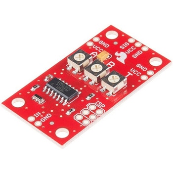
SparkFun Servo Trigger - Continuous Rotation
SPARKFUN¥4,898税込¥5,3881個33日以内出荷。Description。The SparkFun Continuous Rotation(CR)Servo Trigger is a small robotics board that simplifies the control of hobby RC servo motors. When an external switch or logic signal changes state, the CR Servo Trigger is able to tell an attached servo motor to move from position A to position B. To use the CR Servo Trigger, you simply connect a hobby servo and a switch, then use the on-board potentiometers to adjust the start/stop positions and the transition time. You can use a hobby servo in your projects without having to do any programming!。When we introduced the original Servo Trigger, we mentioned that it could be reprogrammed to be more useful with continuous rotation servo motors. But reprogramming the firmware is somewhat tedious, and users asked for a Servo Trigger preprogrammed with the continuous rotation logic. With this little board you will be provided an easy way to deploy continuous rotation servos into your projects!。The heart of the CR Servo Trigger is an Atmel ATtiny84 microcontroller, running a small program that implements the servo control features designed for continuous rotation servos. On board each of these CR Servo Triggers you will find three potentiometers:"A" sets the position the servo sits in while the switch is open, "B" sets the position the servo moves to when the switch is closed, and "T" sets the time it takes to get from A to B and back.。Compared with a servo motor, the CR Servo Trigger board draws very little current, roughly 5mA at 5V. Be sure to note that if you're using the CR Servo Trigger to control your motor, the absolute maximum supply voltage that should be applied is 5.5 VDC. Additionally, the SparkFun CR Servo Trigger is designed to make it easy to daisy chain boards - you can simply connect the VCC and GND pads on adjacent boards to each other.。Note:This idea originally came from our friend in the Oakland area, CTP. If you see him, please give him a high-five for us.。SparkFun CR Servo Trigger Hookup Guide。Features。Recommended Voltage:5VDC。Max Voltage:5.5VDC。Current Draw:5mA。Control Continuous Rotation Servos。Three Control Settings。A - sets the position the servo sits in while the switch is open。B - sets the position the servo moves to when the switch is closed。C - sets the time it takes to get from A to B and back。Easy Control with Potentiometers。Configurable Input Polarity。Configurable Response Mode。Compatible with Analog Servos。ISP Header Pins Available for Reprogramアズワン品番67-0429-21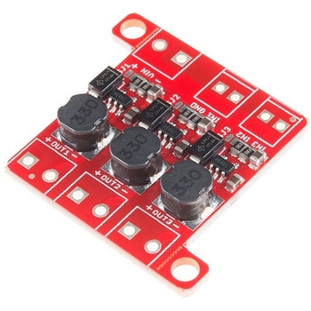
PicoBuck LED Driver
SPARKFUN¥5,298税込¥5,8281個33日以内出荷Description。The PicoBuck LED Driver is an economical and easy to use driver that will allow you to control and blend three different LEDs on three different channels. By default, each channel is driven at 330mA; that current can be reduced by either presenting an analog voltage or a PWM signal to the board. Version 12 of the board adds a solderable jumper that can be closed to increase the maximum current to 660mA. The new voltage regulator also increased the voltage rating on the various components on the board, allowing it to be used up to the full 36V rating of the AL8805 part.。Three signal inputs are provided for dimming control. You can use the PWM signal from an Arduino or your favorite microcontroller to dim each channel individually, or you can tie them all to the same PWM for simultaneous dimming. Dimming can be done by an analog voltage(20%-100% of max current by varying voltage from .5V-2.5V)or by PWM(so long as PWM minimum voltage is less than .4V and maximum voltage is more than 2.4V)for a full 0-100% range. A small jumper is provided for each channel to allow you to increase the drive strength from 330mA to 660mA. Two mounting holes for 4-40 or M3 screws are provided on either side of the board. They are perforated so they can be easily snapped off with a pair of pliers, if a smaller footprint is desired.。Note:。If you're going to use screw terminals, this board uses two different sizes. Check the related products for both sizes you'll need.。Note:。The PicoBuck LED Driver was made in collaboration with Ethan Zonca. A portion of each sale is given back to him.アズワン品番67-0420-83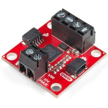
SparkFun Qwiic Motor Driver
SPARKFUN¥6,698税込¥7,3681個33日以内出荷。Description。The SparkFun Qwiic Motor Driver takes all the great features of the Serial Controlled Motor Driver(SCMD)and miniaturizes them, adding Qwiic ports for plug and play functionality. Boasting the same 4245 PSOC and 2-channel motor ports as the SCMD, the SparkFun Qwiic Motor Driver is designed to communicate over I2C to make setting up your next robotic project as fast and easy as possible! Utilizing our handy Qwiic system and screw terminals for motor and power hook-up, no soldering is required to connect it to the rest of your system.。With 1.2A steady state drive per channel(1.5A peak)and 127 levels of DC drive strength, this little Qwiic board is perfect for your small DC motor driver needs. Since the Qwiic Motor Driver is a 3.3V logic device, you'll need to use a logic level converter to interface to 5V.。The I2C address of the Qwiic Motor Driver is 0x5D and is jumper selectable to 0x58, 0x59, 0x5A, 0x5B, ... 0x63.。The SparkFun Qwiic Connect System is an ecosystem of I2C sensors, actuators, shields and cables that make prototyping faster and less prone to error. All Qwiic-enabled boards use a common 1mm pitch, 4-pin JST connector. This reduces the amount of required PCB space, and polarized connections mean you can't hook it up wrong.。Need a custom board? This component can be found in SparkFun's A La Carte board builder. You can have a custom design fabricated with this component - and your choice of hundreds of other sensors, actuators and wireless devices - delivered to you in just a few weeks.。Get Started With the Qwiic Motor Driver Hookup Guide。Features。1.5 A peak drive per channel, 1.2 A steady state。Operates from 3 to 11 Volts with 12V absolute max。3.3V default VCC and logic。127 levels of DC drive strength.。Controllable by I2C or TTL UART signals。Direction inversion on a per motor basis。Global Drive enable。Exposed small heat sink shape。Several I2C addresses, default UART bauds available。Adjustable I2C Address:0x5D Default。2x Qwiic Connectors。。Documents。Schematic。Eagle Files。Board Dimensions。Hookup Guide。Arduino Library。Python Module。Github Hardware Repoアズワン品番67-0426-33