カテゴリ
- 学童・教育用品(11)
- 制御機器(2)
絞り込み
ブランド
- SPARKFUN
- モノタロウ(1)
- KNITTER-SWITCH(25)
- トヨタ(178)
- ミツビシ(208)
- サンワダイレクト(18)
- フエニックス・コンタクト(6)
- ナカバヤシ(18)
- DENALI(14)
- HIDISC(2)
- ホンダ(1,352)
- 三菱ふそう(659)
- SWITCHCRAFT(157)
- 日野自動車(132)
- エレコム(130)
- NKKスイッチズ(旧:日本開閉器)(92)
- piaggio(ピアッジオグループ)(82)
- KTM(64)
- BMW(56)
- MAZDA(マツダ)(44)
- ブランドをもっと見る
「switch」の検索結果
特価

 Large Piezo Alarm - 16 ToneSPARKFUN
¥2,498税込¥2,748
1個
33日以内出荷
DescriptionThis Piezo Alarm is a great option for when you need an audible alarm(or are just looking for a way to prank your friends). This alarm has 16 different output options that can be changed with the DIP switches on the unit. Select Continuous, Chime, Intermittent, Warble, or Pulsating and amaze your friends.FeaturesOperating Voltage:5-16VdcOperating Frequency:3KHzWarble Frequency:2.8KHz to 3.2KHzDiameter:35.8mm, Height 35.7mm103 dB(A)at 16V at 61cm90 dB(A)at 5V at 61cm
アズワン品番67-0420-87
 Hologram eUICC SIM CardSPARKFUN
¥1,998税込¥2,198
1個
33日以内出荷
DescriptionThe Hologram eUICC SIM Card is a mix between legacy and new technology when cellular service is needed your project. This eUICC SIM Card enables profile switching capabilities so you can dynamically change the subscriber profile while your chosen devices are in the field, over-the-air. For those looking for IoT cellular service with no intentions on switching cellular carriers, this SIM card is for you.eUICC features are limited to certain modules at this point. This includes the u-blox SARA-R4 module used on our SparkFun LTE CAT M1/NB-IoT Shield - SARA-R4. For these situations, the functionality will be that of a normal SIM with cellular service through Hologram. You won't be able to change carriers.FeaturesTemperature Range:-25C to 85CNano SIM 8.8mm x 12.3mmMinimum 500,000 Read/write cyclesMinimum 25 yrs at 25℃ Data retention
アズワン品番67-0420-79
 SparkFun Breadboard Power Supply 5V/3.3VSPARKFUN
¥3,998税込¥4,398
1個
33日以内出荷
Here is a very simple breadboard power supply kit that takes power from a DC wall wart and outputs a selectable 5V or 3.3V regulated voltage. The .1" headers are mounted on the bottom of the PCB for simple insertion into a breadboard. Pins labeled VCC and GND plug directly into the power lines. The lone pair of pins have no electrical connection but help support the PCB.There are two pins available within the barrel jack footprint. Any stripped +/- DC supply can be connected instead of the barrel connector. Board has both an On/Off switch and a voltage select switch(3.3V/5V).Comes as a bag of parts kit and is easily assembled if you can follow the silkscreen indicators and have beginning experience with a soldering iron. You will need to read the resistor bands or use a multimeter to determine the resistor sizes.Dimensions:1.25x1.25"Kit Includes:DC Barrel Connector(2.1mm center positive)TO-220 Voltage Regulator(LM317 1.5A max current)1N4004 Reverse Protection Diode100uF 25V Capacitor10uF 25V Capacitor0.1uF 50V CapacitorRed Power LED - High Brightness2×SPDT Slide Switch4×0.1" Header Pins2×330 Resistor 1/6W390 Resistor 1/6W240 Resistor 1/6WBare PCB with Silkscreen IndicatorsPTC resettable fuse
仕様●項目1:組込み(組立てキット)●項目2:電源●項目4:リニア電源●項目8:ブレッドボード用電源アズワン品番67-0454-01
 SparkFun Nano Power Timer - TPL5110SPARKFUN
¥2,398税込¥2,638
1個
欠品中
DescriptionSometimes we want our projects on, but sometimes we want to turn them off for a while to save power. The SparkFun Nano Power Timer will run while only consuming minimal power(approximately 35nA)and turn your project on after a set amount of time. When you are done polling your sensors, posting data to the web, writing to your logger, or planning world domination, your microcontroller can tell the Nano Power Timer to turn off the power. No more running your microcontroller all day when you only want to read the ambient temperature once per hour.The TPL5110 delay is configured with the use of resistors. We've added a six-way DIP switch to select one of the five preinstalled resistors. The sixth switch is attached to a pad to add your own PTH(or SMD)resistor. The delays associated with the preinstalled headers are shown on the bottom of the board for quick setup. Additionally, you can select more than one switch to combine the resistors in parallel(up to 26 options not including the custom resistor), check out the hookup guide for a nice chart as to the total resistance and corresponding delay for each combination.The Nano Power Timer can handle voltages between 1.8V and 5.5V as well as current up to 1.1A with times from 100ms to two hours(preconfigured settings range from 30s to 2h). You will find a button on the board which will allow you a quick override to the delay so you can turn your project on whenever you like.Get Started with the SparkFun Nano Power SwitchFeaturesSupply Voltage:1.8V to 5.5VCurrent consumption at 2.5V:35nA Typical(50nA Max)Selectable Time intervals:100ms to 7200s(2 hours)Timer Accuracy:1%
アズワン品番67-0425-68
 LilyPad E-Sewing ProtoSnapSPARKFUN
¥2,198税込¥2,418
1個
33日以内出荷
DescriptionThe LilyPad E-Sewing ProtoSnap is a great way to explore how buttons and switches behave in simple e-sewing circuits before crafting your project. Like other LilyPad ProtoSnap series boards, the individual pieces of the board are pre-wired --- allowing you to try out the function of the circuit before sewing. There is no programming required to use this ProtoSnap, and it can be used right away!The E-Sewing ProtoSnap includes three white LilyPad LEDs:two connected to a LilyPad Slide Switch and one connected to a LilyPad Button Board. A LilyPad Coin Cell Battery Holder with a CR2032 coin cell battery provides all the power you need for the circuit. All you need to do is design how you want your project to be laid out, and then snap everything apart!Note:A portion of this sale is given back to Dr. Leah Buechley for continued development and education in e-textiles.Note:Due to the requirements of shipping the included battery, orders may take longer to process and therefore do not qualify for same-day shipping. Additionally, these batteries cannot be shipped via Ground or Economy methods to Alaska or Hawaii. Sorry for any inconvenience this may cause.Get Started with the LilyPad E-Sewing ProtoSnap Guide
アズワン品番67-0422-55
 Enclosure - Aluminum 112x61x31mmSPARKFUN
¥2,798税込¥3,078
1個
欠品中
DescriptionThese are our small, beefy aluminum enclosures, which have been built tough enough to withstand a truck. This 2mm-thick, die-cast enclosure is rated IP54 against dust and splashing water. Because it's aluminum, it's easy to cut and drill so that you can add LCD screens, buttons and cable connections. If you want to "pretty up" your project, hit this with some fine-grit sand paper and buff it or just spray paint it!These enclosures are perfect for producing "stomp box" style effects pedals. Try combining this with a stomp switch and some of your own secret sauce circuitry to build a sweet custom pedal.The lid mates nicely to the top of the enclosure and is secured with 10mm long #6-32 screws(included). This aluminum enclosure version features a smoother metal finish as well as a more structurally sound design.Features112x61x31mm
アズワン品番67-0425-20
 SparkFun FT231X BreakoutSPARKFUN
¥4,598税込¥5,058
1個
33日以内出荷
DescriptionIntroducing the SparkFun FT231X Breakout board, complete with the full UART hardware handshake feature! The pin-out of this board matches the FTDI cable to work with official Arduino and cloned Arduino boards. It can also be used for general serial applications.This board still brings out the DTR pin as opposed to the RTS pin of the FTDI cable. The DTR pin allows an Arduino target to auto-reset when a new Sketch is downloaded. This is a really nice feature to have and allows a sketch to be downloaded without having to hit the reset button. This board will auto-reset any Arduino board that has the reset pin brought out to a 6-pin connector.The coolest thing about the FT231X Breakout is that we have broken out ALL the pins for your use, making this board all the more hackable! It also uses a common microUSB jack.One of the features of this board is a jumper on the back, which allows the VCC output to be configured to either 3.3V or 5V. This board ships default to 5V, but you can cut the default trace and add a solder jumper if you need to switch to 3.3V. It should be noted that the max input of the FT231X is only 3.3V, but it can operate down to 1.8V with external pull-ups and is also 5V tolerant.
アズワン品番67-0419-85
 SparkFun Real Time Clock Module - RV-1805 QwiicSPARKFUN
¥7,798税込¥8,578
1個
33日以内出荷
DescriptionGet with the times, already! This SparkFun Real Time Clock(RTC)Module is a Qwiic-enabled breakout board for the RV-1805 chipset. The RTC is ultra-low power(running at only about 22nA in its lowest power setting)so it can use a supercapacitor for backup power instead of a normal battery. This means you get plenty of charge and discharge cycles without any degradation to the "battery." To make it even easier to get your readings, all communication is enacted exclusively via I2C, utilizing our handy Qwiic system so no soldering is required to connect it to the rest of your system. However, we still have broken out 0.1"-spaced pins in case you prefer to use a breadboard.This RTC module's built in RV-1805 has not one, but two internal oscillators:a 32.768kHz tuning fork crystal and a low power RC based oscillator and can automatically switch between the two using the more precise crystal to correct the RC oscillator every few minutes. This feature allows the module to maintain a very accurate date and time with the worst case being +/- about three minutes over a year. The RV-1805 also has a built in trickle charger so as soon as the RTC is connected to power the it will be fully charged in under 10 minutes and has the ability to switch power to other systems allowing it to directly turn on or off a power hungry device such as a microcontroller or RF engine.There is also the option to add a battery to the board if the supercapacitor just isn't going keep your project powered long enough(keep in mind, the supercap can hypothetically make the board keep time for around 35 days), you can solder on an external battery. That means you can let board sit with no power or connection to the outside world and the current hour/minute/second/date will be maintained.Note:The I2C address of the RV-1805 is 0x69 and is hardware defined. A multiplexer/Mux is required to communicate to multiple RV-1805 sensors on a single bus. If you need to use more than one RV-1805 sensor consider using the Qwiic Mux Breakout.The SparkFun Qwiic connect system is an ecosystem of I2C sensors, actuators, shields and cables that make prototyping faster and less prone to error. All Qwiic-enabled boards use a common 1mm pitch, 4-pin JST connector. This reduces the amount of required PCB space, and polarized connections mean you can't hook it up wrong.Get Started with the RV-1805 Real Time Clock Module GuideFeaturesOperating Voltage(Startup):1.6V - 3.6VOperating Voltage(Timekeeping):1.5V - 3.6VOperating Temperature:-40℃ - 85℃Time Accuracy:±2.0 ppmCurrent Consumption:22nA(Typ.)I2C Address:0xD2Supercapacitor for Backup Power2x Internal Oscillators2x Qwiic Connectors
アズワン品番67-0420-02
 LilyPad E-Sewing ProtoSnap KitSPARKFUN
¥4,298税込¥4,728
1個
33日以内出荷
DescriptionThe LilyPad E-Sewing ProtoSnap Kit is a great way to incorporate buttons and switches into an e-textile project without any programming required. Like other LilyPad ProtoSnap series boards, the individual pieces of the included E-Sewing ProtoSnap are pre-wired --- allowing you to try out the function of the circuit before sewing. We have also included a CR2032 battery, needle set, conductive thread bobbin and a swatch of white felt. With all of these parts combined and the featured guide(found in the Documents tab), you will be able to plan and create fantastic projects straight out of the box!The E-Sewing ProtoSnap includes three white LilyPad LEDs:two connected to a LilyPad Slide Switch and one connected to a LilyPad Button Board. A LilyPad Coin Cell Battery Holder with the included CR2032 coin cell battery provides all the power you need for the circuit. All you need to do is design how you want your project to be laid out, and then snap everything apart!Note:A portion of this sale is given back to Dr. Leah Buechley for continued development and education in e-textiles.Note:Due to the requirements of shipping the battery in this kit, orders may take longer to process and therefore do not qualify for same-day shipping. Additionally, these batteries cannot be shipped via Ground or Economy methods to Alaska or Hawaii. Sorry for any inconvenience this may cause.Get Started with the LilyPad E-Sewing ProtoSnap Guide
アズワン品番67-0424-14
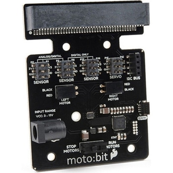 SparkFun moto:bit - micro:bit Carrier Board QwiicSPARKFUN
¥9,398税込¥10,338
1個
33日以内出荷
DescriptionThe SparkFun moto:bit is a fully loaded "carrier" board for the micro:bit that, when combined with the micro:bit, provides you with a fully functional robotics platform. The moto:bit offers a simple, beginner-friendly robotics controller capable of operating a basic robotics chassis. Onboard each moto:bit are multiple I/O pins, as well as a vertical Qwiic connector, capable of hooking up servos, sensors and other circuits. At the flip of the switch you can get your micro:bit moving!The moto:bit connects to the micro:bit via an updated SMD, edge connector at the top of the board, making setup easy. This creates a handy way to swap out micro:bits for programming, while still providing reliable connections to all of the different pins on the micro:bit. We have also included a basic barrel jack on the moto:bit that is capable of providing power to anything you connect to the carrier board.The micro:bit is a pocket-sized computer that lets you get creative with digital technology. Between the micro:bit and our shield-like bit boards you can do almost anything while coding, customizing and controlling your micro:bit from almost anywhere! You can use your micro:bit for all sorts of unique creations, from robots to musical instruments and more. At half the size of a credit card, this versatile board has vast potential!Note:The SparkFun moto:bit doesNOTinclude a micro:bit board. The micro:bit will need to be purchased separately.Get started with the moto:bit GuideFeaturesMore reliable Edge connector for easy use with the micro:bitFull H-Bridge for control of two motorsControl servo motorsVertical Qwiic ConnectorI2C port for extending functionalityPower and battery management onboard for the micro:bit
アズワン品番67-0422-89
 Collet and Nut - 0.25in. ER-11SPARKFUN
¥9,698税込¥10,668
1個
33日以内出荷
DescriptionIf you'd like to use a larger tool in your Nomad, this collet and nut will let you use tools with a .25" shank. The extra collet nut included will let you quickly switch between collets without having to remove them from the collet nut.
アズワン品番67-0428-61
 SparkFun Servo Trigger - Continuous RotationSPARKFUN
¥4,898税込¥5,388
1個
33日以内出荷
DescriptionThe SparkFun Continuous Rotation(CR)Servo Trigger is a small robotics board that simplifies the control of hobby RC servo motors. When an external switch or logic signal changes state, the CR Servo Trigger is able to tell an attached servo motor to move from position A to position B. To use the CR Servo Trigger, you simply connect a hobby servo and a switch, then use the on-board potentiometers to adjust the start/stop positions and the transition time. You can use a hobby servo in your projects without having to do any programming!When we introduced the original Servo Trigger, we mentioned that it could be reprogrammed to be more useful with continuous rotation servo motors. But reprogramming the firmware is somewhat tedious, and users asked for a Servo Trigger preprogrammed with the continuous rotation logic. With this little board you will be provided an easy way to deploy continuous rotation servos into your projects!The heart of the CR Servo Trigger is an Atmel ATtiny84 microcontroller, running a small program that implements the servo control features designed for continuous rotation servos. On board each of these CR Servo Triggers you will find three potentiometers:"A" sets the position the servo sits in while the switch is open, "B" sets the position the servo moves to when the switch is closed, and "T" sets the time it takes to get from A to B and back.Compared with a servo motor, the CR Servo Trigger board draws very little current, roughly 5mA at 5V. Be sure to note that if you're using the CR Servo Trigger to control your motor, the absolute maximum supply voltage that should be applied is 5.5 VDC. Additionally, the SparkFun CR Servo Trigger is designed to make it easy to daisy chain boards - you can simply connect the VCC and GND pads on adjacent boards to each other.Note:This idea originally came from our friend in the Oakland area, CTP. If you see him, please give him a high-five for us.SparkFun CR Servo Trigger Hookup GuideFeaturesRecommended Voltage:5VDCMax Voltage:5.5VDCCurrent Draw:5mAControl Continuous Rotation ServosThree Control SettingsA - sets the position the servo sits in while the switch is openB - sets the position the servo moves to when the switch is closedC - sets the time it takes to get from A to B and backEasy Control with PotentiometersConfigurable Input PolarityConfigurable Response ModeCompatible with Analog ServosISP Header Pins Available for Reprogram
アズワン品番67-0429-21