カテゴリ
- 学童・教育用品(26)
絞り込み
ブランド
- SPARKFUN
- onsemi(468)
- TAIWAN SEMICONDUCTOR(41)
- 工進(11)
- RS PRO(10)
- AMPHENOL(7)
- ナカトミ(6)
- ホンダ(5)
- MICROCHIP(4)
- アーキサイト(4)
- NSK(日本精工)(3)
- TORCH(3)
- FAIRCHILD SEMICONDUCTOR(3)
- シュナイダーエレクトリック(3)
- ミルウォーキーツール(3)
- 京セラインダストリアルツールズ(3)
- エスコ(2)
- テックサス(旧:本庄厨房機器製作所)(2)
- デンゲン(2)
- ブランドをもっと見る
「torch」の検索結果
特価
 の全商品がキャンペーンコード入力で通常価格より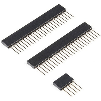
Teensy Stackable Header Kit Extended
SPARKFUN¥619税込¥6811個5日以内出荷。Description。These headers are made to work with the Teensy 4.1, Teensy 3.6, and Teensy 3.5 development boards. Each set of headers allows for your Teensy to be easily incorporated into a breadboard circuit or attach a shield on top of the board. This kit includes three headers(two 24-pin, and one 5-pin), enough to connect your chosen Teensy in any configuration you need!アズワン品番67-0425-96
Mini Load Cell - 500g, Straight Bar TAL221
SPARKFUN¥4,998税込¥5,4981個33日以内出荷Description。This miniature straight bar load cell(sometimes called a strain gauge)can translate up to 500g of pressure(force)into an electrical signal. Each load cell is able to measure the electrical resistance that changes in response to, and proportアズワン品番67-0426-83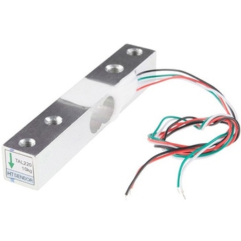
Load Cell - 10kg, Straight Bar TAL220
SPARKFUN¥3,998税込¥4,3981個33日以内出荷Description。This straight bar load cell(sometimes called a strain gauge)can translate up to 10kg of pressure(force)into an electrical signal. Each load cell is able to measure the electrical resistance that changes in response to, and proportional of, the strain(e.g. pressure or force)applied to the bar. With this gauge you will be able to tell just how heavy an object is, if an object's weight changes over time, or if you simply need to sense the presence of an object by measuring strain or load applied to a surface.。Each straight bar load cell is made from an aluminum-alloy and is capable of reading a capacity of 10kg. These load cells have four strain gauges that are hooked up in a wheatstone bridge formation. The color code on the wiring is as follows:red = E+, green = O+, black = E-, and white = O-. Additionally, these load cells offer an IP66 protection rating and feature two M4 and two M5 sized through-holes for mounting purposes.。Get Started with the Load Cell Guide。Features。80mm×12.7mm×12.7mm, 250mm Wireアズワン品番67-0426-52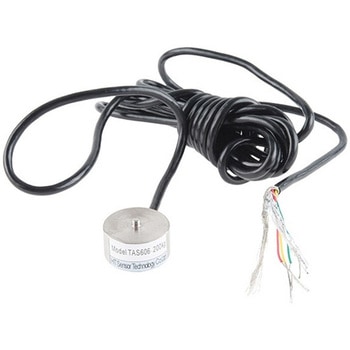
Load Cell - 200kg, Disc TAS606
SPARKFUN¥30,980税込¥34,0781個33日以内出荷Description。This disc load cell(sometimes called a strain gauge)can translate up to a whopping 200kg of pressure(force)into an electrical signal. Each load cell is able to measure the electrical resistance that changes in response to, and proportiアズワン品番67-0426-54
SparkFun MicroMod Qwiic Carrier Board - Single
SPARKFUN¥3,500税込¥3,8501個33日以内出荷Description。The MicroMod Qwiic Carrier Board can be used to rapidly prototype with other Qwiic devices. The MicroMod M.2 socket provides users the freedom to experiment with any processor board in the MicroMod ecosystem. This board also features two Qwiic connectors and four 4-40 screw inserts to connect and mount Qwiic devices.。This version of the SparkFun MicroMod Qwiic Carrier Board features a single port for our standard 1in. by 1in. Qwiic Breakouts. However, you aren't beholden to attaching just one Qwiic breakout since you are able to stack the boards on top of each other, allowing you to hook up a full circuit of Qwiic sensors and accessories to fully utilize your next project!。MicroMod is a modular interface ecosystem that connects a microcontroller "processor board" to various "carrier board" peripherals. Utilizing the M.2 standard, the MicroMod standard is designed to easily swap out processors on the fly. Pair a specialized carrier board for the project you need with your choice of compatible processor!。Get Started With the MicroMod Qwiic Carrier Board Guide。Features。M.2 MicroMod(Processor Board)Connector。USB-C Connector。3.3V 1A Voltage Regulator。Qwiic Connectors。Boot/Reset Buttons。Charge Circuit。Four 4-40 Insertsアズワン品番67-0423-50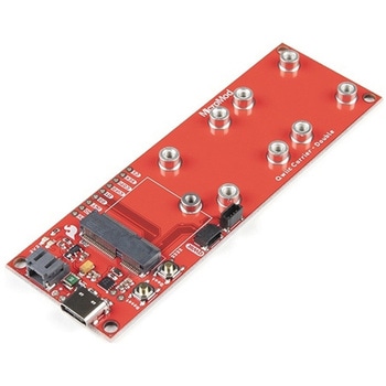
SparkFun MicroMod Qwiic Carrier Board - Double
SPARKFUN¥4,298税込¥4,7281個33日以内出荷Description。The MicroMod Qwiic Carrier Board can be used to rapidly prototype with other Qwiic devices. The MicroMod M.2 socket provides users the freedom to experiment with any processor board in the MicroMod ecosystem. This board also features two Qwiic connectors and eight 4-40 screw inserts to connect and mount Qwiic devices.。This version of the SparkFun MicroMod Qwiic Carrier Board features two ports for our standard 1in. by 1in. Qwiic breakouts. However, you aren't beholden to attaching just a duo of Qwiic breakouts since you are able to stack the boards on top of each other, allowing you to hook up a full circuit of Qwiic sensors and accessories to fully utilize your next project!。MicroMod is a modular interface ecosystem that connects a microcontroller "processor board" to various "carrier board" peripherals. Utilizing the M.2 standard, the MicroMod standard is designed to easily swap out processors on the fly. Pair a specialized carrier board for the project you need with your choice of compatible processor!。Get Started With the MicroMod Qwiic Carrier Board Guide。Features。M.2 MicroMod(Processor Board)Connector。USB-C Connector。3.3V 1A Voltage Regulator。Qwiic Connectors。Boot/Reset Buttons。Charge Circuit。Eight 4-40 Insertsアズワン品番67-0423-51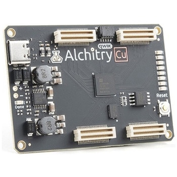
Alchitry Cu FPGA Development Board Lattice iCE40 HX
SPARKFUN¥15,980税込¥17,5781個33日以内出荷Description。If you are not needing a lot of power to start your FPGA adventure, or are looking for a more economical option, the Alchitry Cu FPGA Development Board might be the perfect option for you! The Alchitry Cu is a "lighter" FPGA version than the Alchitry Au but still offers something completely unique. FPGAs, or Field-Programmable Gate Arrays, are an advanced development board type for engineers and hobbyists alike to experience the next step in programming with electronics. The Cu truly exemplifies the trend of more affordable and increasingly powerful FPGA boards arriving each year. This board is a fantastic starting point into the world of FPGAs and the heart of your next project. Finally, now that this board is built by SparkFun, we added a Qwiic connector for easy I2C integration!。The Alchitry Cu uses the Lattice iCE40 HX FPGA with 7680 logic cells and is supported by the open source tool chain Project IceStorm. The Cu possesses 79 IO pins with eight general purpose LEDs; a 100MHz on-board clock that can be manipulated internally by the FPGA; a USB-C connector to configure and power the board; and a USB to serial interface for data transfer.。By adding stackable expansion boards similar to shields or HATs called "Elements," the Alchitry Cu is able to expand its own hardware capabilities by adding prototyping spaces, buttons, LEDs, and more!。The SparkFun Qwiic Connect System is an ecosystem of I2C sensors, actuators, shields and cables that make prototyping faster and less prone to error. All Qwiic-enabled boards use a common 1mm pitch, 4-pin JST connector. This reduces the amount of required PCB space, and polarized connections mean you can't hook it up wrong.。Get Started with our Learning FPGA Tutorials。Features。Lattice iCE40-HX8K FPGA - 7680 logic elements。79 IO pins(3.3V logic level)。USB-C to configure and power the board。Eight general purpose LEDs。One button(typically used as a reset)。100MHz on-board clock(can be multiplied internally by the FPGA)。Powered with 5V through USB-C port, 0.1" holes, or headers。USB to serial interface for data transfer(up to 12Mbaud)。Qwiic Connector。Dimensions of 65mm×45mm。。Examples。First FPGA Project - Getting Fancy with PWM。External IO and Metastabilityアズワン品番67-0423-08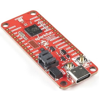
SparkFun Thing Plus - RP2040
SPARKFUN¥6,698税込¥7,3681個33日以内出荷Description。The SparkFun Thing Plus - RP2040 is a low-cost, high performance board with flexible digital interfaces featuring the Raspberry Pi Foundation's RP2040 microcontroller. Besides the Thing Plus or。Feather。footprint(with 18 GPIO pins), the board also includes an SD card slot, 16MB(128Mbit)flash memory, a JST single cell battery connector(with a charging circuit and fuel gauge sensor), an addressable WS2812 RGB LED, JTAG PTH pins, four(4-40 screw)mounting holes, and our signature Qwiic connector.。The RP2040 contains two ARM Cortex-M0+ processors(up to 133MHz)and features:264kB of embedded SRAM in six banks。6 dedicated IO for SPI Flash(supporting XIP)。30 multifunction GPIO:Dedicated hardware for commonly used peripherals。Programmable IO for extended peripheral support。Four 12-bit ADC channels with internal temperature sensor(up to 0.5 MSa/s)。USB 1.1 Host/Device functionality。The RP2040 is supported with both C/C++ and MicroPython cross-platform development environments, including easy access to runtime debugging. It has UF2 boot and floating-point routines baked into the chip. While the chip has a large amount of internal RAM, the board includes an additional 16MB of external QSPI flash memory to store program code.。The SparkFun Qwiic Connect System is an ecosystem of I2C sensors, actuators, shields and cables that make prototyping faster and less prone to error. All Qwiic-enabled boards use a common 1mm pitch, 4-pin JST connector. This reduces the amount of required PCB space, and polarized connections mean you can't hook it up wrong.。Get Started With the Thing Plus RP2040 Hookup Guide。Features。SparkFun Thing Plus - RP2040 Features。Raspberry Pi Foundation's RP2040 microcontroller。16MB QSPI Flash Memory。JTAG PTH Pins。Thing Plus(or Feather)Form-Factor:18[1]x Multifunctional GPIO Pins[2]。Four available 12-bit ADC channels with internal temperature sensor(500kSa/s)。Up to eight 2-channel PWM。Up to two UARTs。Up to two I2C buses。Up to two SPI buses。USB-C Connector:USB 1.1 Host/Device functionality。2-pin JST Connector for a LiPo Battery。(not included)。500mA charging circuit。Qwiic Connector。Buttons:Boot。Reset。LEDs:PWR。- Red 3.3V power indicator。CHG。- Yellow battery charging indicator。25。- Blue status/test LED(。GPIO 25。)。WS2812。- Addressable RGB LED(。GPIO 08。)。Four Mounting Holes:4-40 screw compatible。Dimensions:2.3"×0.9"。RP2040 General Features。Dual Cortex M0+ processors, up to 133 MHz。264 kB of embedded SRAM in 6 banks。6 dedicated IO for QSPI flash, supporting execute in place(XIP)。30 programmable IO for extended peripheral support。SWD interface。Timer with 4 alarms。Real time counter(RTC)。USB 1.1 Host/Device functionality。Supported programming languages。MicroPython。C/C++。1.。Note:。GPIO 08。is not included in this count, as it passes through the WS2812 addressable RGB LED first.。GPIO 07。and。GPIO 23。are counted as a single GPIO because they are tied together.。2.。Note:The GPIO pins are programmable so you can reconfigure the pins! Check out the RP2040 datasheet for more information on the GPIO functionality.アズワン品番67-0423-56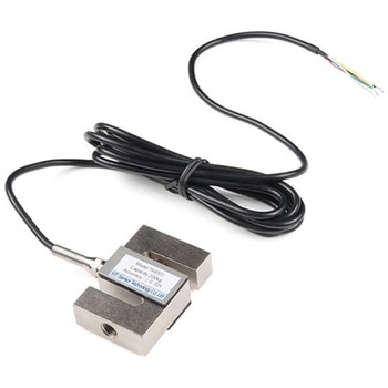
Load Cell - 200kg, S-Type TAS501
SPARKFUN¥29,980税込¥32,9781個33日以内出荷Description。This S-Type load cell(sometimes called a strain gauge)can translate up to 200kg of pressure(force)into an electrical signal. Each load cell is able to measure the electrical resistance that changes in response and proportion to the strain(e.g., pressure or force)applied to the form. With this gauge you will be able to tell just how heavy an object is, if an object's weight changes over time, or if you simply need to sense the presence of an object by measuring strain or load applied to a surface.。Each straight bar load cell is made from an alloy steel and is capable of reading a capacity up to 200kg. These load cells have four strain gauges that are hooked up in a Wheatstone bridge formation. The color code on the wiring is as follows:red = E+, green = O+, black = E-, and white = O-. Additionally, these load cells offer an IP66 protection rating and feature two M4 and two M5 sized through-holes for mounting purposes.。Get Started with the Load Cell Guide。Features。51mm×19mm×76mm, 3m Wireアズワン品番67-0426-66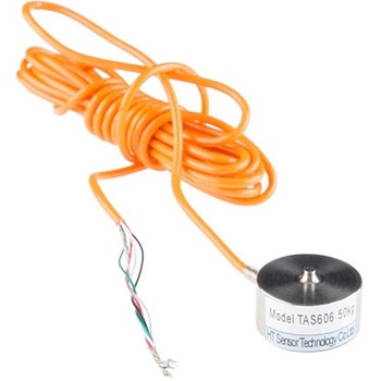
Load Cell - 50kg, Disc TAS606
SPARKFUN¥30,980税込¥34,0781個33日以内出荷Description。This single disc load cell(sometimes called a strain gauge)can translate up to 50kg of pressure(force)into an electrical signal. Each load cell is able to measure the electrical resistance that changes in response to, and proportional of, the strain(e.g. pressure or force)applied to the disc. With this gauge you will be able to tell just how heavy an object is, if an object's weight changes over time, or if you simply need to sense the presence of an object by measuring strain or load applied to a surface.。Disc load cells are a bit easier to mount than bar-style load cells, making them more straightforward to implement into a design.。Each load cell is made from an steel-alloy and is capable of reading a capacity of 50kg. These load cells have four strain gauges that are hooked up in a wheatstone bridge formation. The color code on the wiring is as follows:red = E+, green = O+, black = E-, and white = O-. Additionally, these load cells offer an IP66 protection rating.。Get Started with the Load Cell Guide。Features。20mm×11mm, 2000mm Wireアズワン品番67-0426-53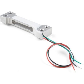
Mini Load Cell - 100g, Straight Bar TAL221
SPARKFUN¥5,198税込¥5,7181個33日以内出荷Description。This miniature straight bar load cell(sometimes called a strain gauge)can translate up to 100g of pressure(force)into an electrical signal. Each load cell is able to measure the electrical resistance that changes in response to, and proportional of, the strain(e.g. pressure or force)applied to the bar. With this gauge you will be able to tell just how heavy an object is, if an object's weight changes over time, or if you simply need to sense the presence of an object by measuring strain or load applied to a surface.。Each straight bar load cell is made from an aluminum-alloy and is capable of reading a capacity of 100g. These load cells have four strain gauges that are hooked up in a wheatstone bridge formation. The color code on the wiring is as follows:red = Exc+, green = Sig+, black = Exc-, and white = Sig-. Additionally, these load cells offer an IP65 protection rating and features four M3 sized through-holes for mounting purposes.。Get Started with the Load Cell Guide。Features。Capacity:100g。Material:Aluminum-Alloy。Parallel Beam Type。IP65 Rating。47mm×12mm×6mm, 110mm Wireアズワン品番67-0426-82
Load Cell - 5kg, Straight Bar TAL220B
SPARKFUN¥5,498税込¥6,0481個33日以内出荷。Description。This straight bar load cell(sometimes called a strain gauge)can translate up to 5kg of pressure(force)into an electrical signal. Each load cell is able to measure the electrical resistance that changes in response to, and proportional of, the strain(e.g. pressure or force)applied to the bar. With this gauge you will be able to tell just how heavy an object is, if an object's weight changes over time, or if you simply need to sense the presence of an object by measuring strain or load applied to a surface.。Each straight bar load cell is made from an aluminum-alloy and is capable of reading a capacity of 5kg. These load cells have four strain gauges that are hooked up in a wheatstone bridge formation. The color code on the wiring is as follows:red = Exc+, green = Sig+, black = Exc-, and white = Sig-. Additionally, these load cells offer an IP65 protection rating and features two M5 sized through-holes for mounting purposes.。Get Started with the Load Cell Guide。Features。Capacity:5kg。Material:Aluminum-Alloy。Parallel Beam Type。IP65 Rating。55mm×12.7mm×12.7mm, 200mm Wireアズワン品番67-0426-84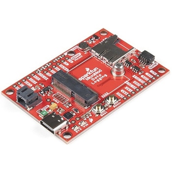
SparkFun MicroMod Data Logging Carrier Board
SPARKFUN¥7,098税込¥7,8081個33日以内出荷Description。The SparkFun MicroMod Data Logging Board offers a highly customizable, low-power data logging platform using the MicroMod system allowing you to choose your own Processor to pair with the Carrier Board. The Data Logging Carrier Board breaks out connections for I2C via a Qwiic connector or standard 0.1"-spaced PTH pins along with SPI and serial UART connections for logging data from peripheral devices using those communication protocols.。The Data Logging Carrier Board allows you to control power to both the Qwiic connector on the board and a dedicated 3.3V power rail for non-Qwiic peripherals so you can pick and choose when to power the peripherals you are monitoring the data from. It also features a charging circuit for single-cell Lithium-ion batteries along with a separate RTC battery-backup circuit to maintain power to a real-time clock circuit on your Processor Board.。MicroMod is a modular interface ecosystem that connects a microcontroller "processor board" to various "carrier board" peripherals. Utilizing the M.2 standard, the MicroMod standard is designed to easily swap out processors on the fly. Pair a specialized carrier board for the project you need with your choice of compatible processor!。Get Started with the MicroMod Data Logging Carrier Board Guide。Features。M.2 MicroMod Connector。microSD socket。USB-C Connector。3.3V 1A Voltage Regulator。Qwiic Connector。Boot/Reset Buttons。RTC Backup Battery Charge Circuit。Independent 3.3V regulators for Qwiic bus and peripheral add-ons。Controlled by digital pins on Processor Board to enable low power sleep modes。Phillips #0 M2.5x3mm screw includedアズワン品番67-0423-16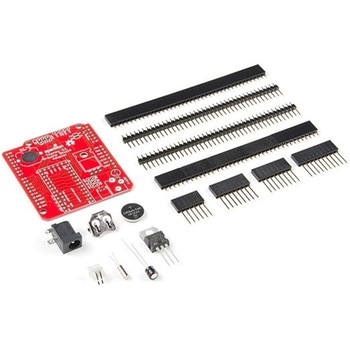
Teensy Arduino Shield Adapter
SPARKFUN¥4,798税込¥5,2781個33日以内出荷Description。The Teensy is an amazing and compact development platform in breadboard friendly form factor, but what if you could incorporate it into the Arduino architecture? The Teensy Arduino Shield Adapter allows you to attach your Teensy and utilize your favorite Arduino shields without the requirement of breadboard or any complicated wiring. Needless to say, the Teensy Arduino Shield Adapter is useful tool for upgrading all of your existing Arduino projects to more powerful controller!。As we stated before, the Teensy Arduino Shield Adapter provides basic Arduino compatibility with your run-of-the-mill shield but there are few other fun features that we've added on, as well. These features include Real Time Clock(RTC)battery, JST battery connector, 4-12V barrel jack connector, an ICSP header, and more. Because this board is simply an adapter, there is no special programming required to start working with the adapter. You will, however, need to program the Teensy for any Arduino shield you'd like to work with.。While the adapter design can fit the Teensy LC footprint, it has been designed to fully utilize the features of the Teensy 3.1. Not all of the features available on the adapter are compatible with the LC so please be sure to check the Hookup Guide in the。Documents。section below to ensure functionality for your project. Please keep in mind that this adapter may be incompatible with some 5V Arduino shields. Please check our hookup guide for more information.。Note:The Teensy Arduino Shield Adapter comes as kit and will need to be soldered together.。Note:Due to the requirements of shipping the batteries in this kit, orders may take longer to process and therefore do not qualify for same-day shipping. Additionally, these batteries can not be shipped via Ground or Economy methods to Alaska or Hawaii. Sorry for any inconvenience this may cause.。Features。Arduino R3 Interface。Real Time Clock Battery。JST Battery Connector。Barrel Jack。I2C Jumpers。ICSP Header。DAC Pin Headerアズワン品番67-0424-36
SparkFun Thing Plus - XBee3 Micro U.FL
SPARKFUN¥16,980税込¥18,6781個33日以内出荷Description。The XBee3 Thing Plus is an ultra capable and easy way for getting into wireless device development. The combination of XBee and Qwiic in a space conscious design represents a much needed update to our XBee offering. With 20 I/O pins and Lithium Polymer Ion battery management, the XBee3 Thing Plus has all the basics for quickly prototyping or developing a connected device such as a remote sensor. The Qwiic connector and JST connector for the battery make for a solder-less option when working with the board which shortens setup time.。The new XBee3 Micro Module provides the classic all-but plug and play 802.15.4 2.4GHz wireless connection(Zigbee 3.0 Protocol)that makes it so desirable, but with a new addition of being programmable with MicroPython(32KB of memory available for it). RF data rates up to 250 Kbps and 200ft indoor ranges and up to 4000ft line-of-sight outdoor range. Communicating with/Configuring the module happens via an AT Command set or the Digi API, X-CTU, both locally or over-the-air. There's even a mobile version of X-CTU now; Digi XBee(R)Mobile.。This variation features a U.FL antenna connector for longer range communications. Check out the related products for compatible antennas.。Get Started With the SparkFun XBee3 Thing Plus Guide。Features。XBee3 Micro Module。Silicon Labs EFR32MG SoC。250Kbps RF, 1Mbps Serial data rates。Indoor/Urban range up to 200 ft(60 m)。Outdoor/RF Line of Sight range up to 4000 ft(1200 m)。+8 dBm transmit power。-103 dBm receiver sensitivity。UART, I2C, SPI Interfaces(SPI currently not available at this time, but broken out on the board)。ISM 2.4GHz Frequency Band(802.15.4)。1MB of memory, 128KB RAM(32KB available for MicroPython)。20 GPIO Pins。Configurable via X-CTU or AT Command set via both USB and Wirelessly(second XBee 3 device required for wireless configuration unless you're using the mobile app)。Qwiic Compatible。On-board charging circuit and connector for 3.3v Lithium Polymer Ion Batteries(see related products for compatible batteries)。2.6VDC - 3.6VDC supply voltage。U.FL Antenna Connectorアズワン品番67-0429-55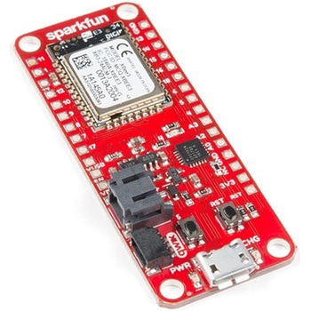
SparkFun Thing Plus - XBee3 Micro Chip Antenna
SPARKFUN¥17,980税込¥19,7781個33日以内出荷Description。The XBee3 Thing Plus is an ultra-capable and easy way for getting into wireless device development. The combination of XBee and Qwiic in a space-conscious design represents a much-needed update to our XBee offering. With 20 I/O pins and Lithium-Polymer Ion battery management, the XBee3 Thing Plus has all the basics for quickly prototyping or developing a connected device such as a remote sensor. The Qwiic connector and JST connector for the battery make for a solder-less option when working with the board which shortens setup time.。The new XBee3 Micro Module provides the classic, near plug and play 802.15.4 2.4GHz wireless connection(Zigbee 3.0 Protocol)that makes it so desirable, but with a new addition of being programmable with MicroPython(32KB of memory available for it). RF data rates up to 250Kbps and 200 ft indoor ranges and up to 4000 ft line-of-sight outdoor range. Communicating with/Configuring the module happens via an AT Command set or the Digi API, X-CTU, both locally or over-the-air. There's even a mobile version of X-CTU now; Digi XBee(R)Mobile.。Note:This variation uses a chip antenna and is not compatible with external antennas.。Get Started With the SparkFun XBee3 Thing Plus Guide。Features。XBee3 Micro Module。Silicon Labs EFR32MG SoC。250Kbps RF, 1Mbps Serial data rates。Indoor/Urban range up to 200 ft(60 m)。Outdoor/RF Line of Sight range up to 4000 ft(1200 m)。+8 dBm transmit power。-103 dBm receiver sensitivity。UART, I2C, SPI Interfaces(SPI currently not available at this time, but broken out on the board)。ISM 2.4GHz Frequency Band(802.15.4)。1MB of memory, 128KB RAM(32KB available for MicroPython)。20 GPIO Pins。Configurable via X-CTU or AT Command set via both USB and Wirelessly(second XBee 3 device required for wireless configuration unless you're using the mobile app)。Qwiic Compatible。On-board charging circuit and connector for 3.3v Lithium Polymer Ion Batteries(see related products for compatible batteries)。2.6VDC - 3.6VDC supply voltage。On-board Chip Antennaアズワン品番67-0429-57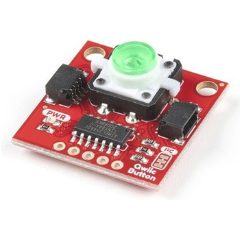
SparkFun Qwiic Button - Green LED
SPARKFUN¥1,698税込¥1,8681個33日以内出荷Description。Buttons are an easy and tactile way to interface with your project, but why would you want to deal with debouncing, polling, and wiring up pull-up resistors? The Qwiic Button with built-in green LED simplifies all of those nasty worries away into an easy to use I2C device! Utilizing our Qwiic Connect System, using the button is as simple as connecting cable and loading up some pre-written code!。If you need multiple buttons for your project, fear not! Each button has configurable I2C address, so you can daisy-chain multiple buttons over Qwiic and still address each one individually. We've got an example in our Arduino library that provides super-easy way to configure your Qwiic Button to whatever I2C address you desire. You can download the library through the Arduino library manager by searching 'SparkFun Qwiic Button' or you can get the GitHub repo as .zip file and install the library from there.。In addition to handling blinking and debouncing, the Qwiic Button has configurable interrupts that can be configured to activate upon button press or click. We've also taken the liberty of implementing FIFO queue onboard the Qwiic Button where it keeps an internal record of when the button was pressed. This means that code on your microcontroller need not waste valuable processing time checking the status of the button but instead can run small function whenever the button is pressed or clicked! For more information on interrupts check out our guide here!。The SparkFun Qwiic Connect System is an ecosystem of I2C sensors, actuators, shields and cables that make prototyping faster and less prone to error. All Qwiic-enabled boards use common 1mm pitch, 4-pin JST connector. This reduces the amount of required PCB space, and polarized connections mean you can't hook it up wrong.。Get Started with the SparkFun Qwiic Button Guide。Features。12mm Green LED Button rated for 50mA。Built in LED can be configured for your desired level of blinkiness!。Each button has configurable I2C address。Configurable interrupts check out our guide here!。FIFO queue。Don't like the color green? Check out the SparkFun Qwiic Button Breakout and add another colored button!。Red LED Tactile Button。Blue LED Tactile Button。Green LED Tactile Button。White LED Tactile Buttonアズワン品番67-0420-14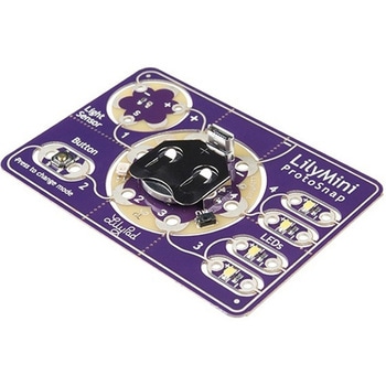
LilyPad LilyMini ProtoSnap
SPARKFUN¥5,998税込¥6,5981個33日以内出荷Description。The LilyMini ProtoSnap is a great way to get started learning about creating interactive e-textile circuits before you start sewing. Like other LilyPad ProtoSnap boards, the LilyMini ProtoSnap has all of its pieces wired together out of the box, enabling you to test the circuit's function before you sew. At the center of the board is a pre-programmed LilyMini microcontroller connected to a LilyPad Light Sensor, LilyPad Button and two pairs of LilyPad LEDs.。The LilyMini ProtoSnap ships with pre-loaded code that uses all the LilyPad pieces connected to it. This sample code has three modes, which can be selected by pressing the LilyPad Button on the bottom-left side of the ProtoSnap. The built-in RGB LED on the LilyMini will change color to indicate which mode has been selected:。White:。All LEDs on.。Magenta:。LEDs fade in and out in a breathing pattern. When the light sensor is covered, LEDs fade faster.。Cyan:。LEDs off. When the light sensor is covered, LEDs will twinkle.。The LilyMini board, at the center of the ProtoSnap, has a built-in battery holder for a CR2032 battery(included). On the opposite side of the LilyMini you will find the SAMD11 brain, which controls the ProtoSnap.。Note:。A portion of this sale is given back to Dr. Leah Buechley for continued development and education in e-textiles.。Note:。The LilyPad LilyMini ProtoSnap does NOT include sewing needles or conductive thread. These items will need to purchased separately.。Warning:You cannot reprogram this product and any attempt at programming is at your own risk!。Get Started with the LilyMini ProtoSnap Guideアズワン品番67-0422-40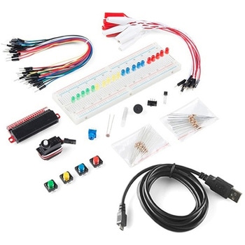
SparkFun Inventor's Kit Bridge Pack for micro:bit
SPARKFUN¥15,980税込¥17,5781個33日以内出荷Description。Do you own micro:bit or micro:bit Go Bundle and want to expand your skills with the new microcontroller? You are in luck! The SparkFun Inventor's Kit Bridge Pack for micro:bit was designed to provide you with an easy way to transform your m:b into full fledged learning kit! Each Bridge Pack includes all of the parts found in the SIK for micro:bit that aren't included with the Go Bundle. With the SIK Bridge Pack for micro:bit you will be able to complete circuits that will teach you how to read sensors, move motors, build Bluetooth(R)devices and more.。The micro:bit is pocket-sized computer that lets you get creative with digital technology. Between the micro:bit and our shield-like bit boards you can do almost anything while coding, customizing and controlling your micro:bit from almost anywhere! You can use your micro:bit for all sorts of unique creations, from robots to musical instruments and more. At half the size of credit card, this versatile board has vast potential!。Note:The Bridge Pack is NOT full SparkFun Inventor's Kit and only includes the parts to complement micro:bit Go Bundle or standalone board. That also means that this kit does。not。include micro:bit, which will need to be purchased separately.。Get started with the micro:bit SIK Experiment Guide。Examples。Circuit 0:Hello, micro:bit!。Circuit 1:Blinking an LED。Circuit 2:Reading Potentiometer。Circuit 3:Reading Photoresistor。Circuit 4:Driving an RGB LED。Circuit 5:Reading an SPDT Switch。Circuit 6:Reading Button Press。Circuit 7:Reading the Temperature Sensor。Circuit 8:Using Servo Motor。Circuit 9:Using Buzzer。Circuit 10:Using the Accelerometer。Circuit 11:Using the Compassアズワン品番67-0424-21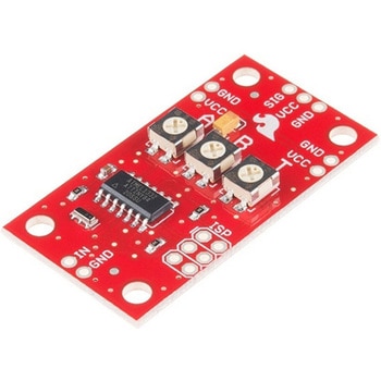
SparkFun Servo Trigger - Continuous Rotation
SPARKFUN¥4,898税込¥5,3881個33日以内出荷。Description。The SparkFun Continuous Rotation(CR)Servo Trigger is a small robotics board that simplifies the control of hobby RC servo motors. When an external switch or logic signal changes state, the CR Servo Trigger is able to tell an attached servo motor to move from position A to position B. To use the CR Servo Trigger, you simply connect a hobby servo and a switch, then use the on-board potentiometers to adjust the start/stop positions and the transition time. You can use a hobby servo in your projects without having to do any programming!。When we introduced the original Servo Trigger, we mentioned that it could be reprogrammed to be more useful with continuous rotation servo motors. But reprogramming the firmware is somewhat tedious, and users asked for a Servo Trigger preprogrammed with the continuous rotation logic. With this little board you will be provided an easy way to deploy continuous rotation servos into your projects!。The heart of the CR Servo Trigger is an Atmel ATtiny84 microcontroller, running a small program that implements the servo control features designed for continuous rotation servos. On board each of these CR Servo Triggers you will find three potentiometers:"A" sets the position the servo sits in while the switch is open, "B" sets the position the servo moves to when the switch is closed, and "T" sets the time it takes to get from A to B and back.。Compared with a servo motor, the CR Servo Trigger board draws very little current, roughly 5mA at 5V. Be sure to note that if you're using the CR Servo Trigger to control your motor, the absolute maximum supply voltage that should be applied is 5.5 VDC. Additionally, the SparkFun CR Servo Trigger is designed to make it easy to daisy chain boards - you can simply connect the VCC and GND pads on adjacent boards to each other.。Note:This idea originally came from our friend in the Oakland area, CTP. If you see him, please give him a high-five for us.。SparkFun CR Servo Trigger Hookup Guide。Features。Recommended Voltage:5VDC。Max Voltage:5.5VDC。Current Draw:5mA。Control Continuous Rotation Servos。Three Control Settings。A - sets the position the servo sits in while the switch is open。B - sets the position the servo moves to when the switch is closed。C - sets the time it takes to get from A to B and back。Easy Control with Potentiometers。Configurable Input Polarity。Configurable Response Mode。Compatible with Analog Servos。ISP Header Pins Available for Reprogramアズワン品番67-0429-21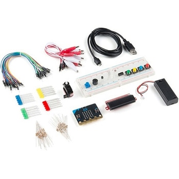
SparkFun Inventor's Kit for micro:bit v2
SPARKFUN¥17,980税込¥19,7781個33日以内出荷Description。The SparkFun Inventor's Kit(SIK)for micro:bit v2 is a great way to get creative, connected and coding with the micro:bit. The SIK for micro:bit v2 provides not only the micro:bit v2 board but everything you need to hook up and experiment with multiple electronic circuits! With the SIK for micro:bit v2 you will be able to complete circuits that will teach you how to read sensors, move motors, build Bluetooth(R)devices and more.。The SparkFun Inventor's Kit for micro:bit is the latest and greatest in single-board computer kits. Surrounding the micro:bit v2 SIK is one core philosophy --- that anyone can(and should)experiment with cutting-edge electronics in a fun and playful way without breaking the bank.。The kit does not require any soldering and is recommended for all users, from beginners to engineers. We have provided a complete Experiment Guide in the Documents tab for you to check out now! If you have ever been interested in learning about electronics, or if you have used the original SparkFun Inventor's Kit and are looking for something new, the SIK for micro:bit is the perfect kit for you!。The micro:bit is a pocket-sized computer that lets you get creative with digital technology. Between the micro:bit and our shield-like bit boards you can do almost anything while coding, customizing and controlling your micro:bit from almost anywhere! You can use your micro:bit for all sorts of unique creations, from robots to musical instruments and more. At half the size of a credit card, this versatile board has vast potential!。。Examples。Circuit 0:Hello, micro:bit!。Circuit 1:Blinking an LED。Circuit 2:Reading a Potentiometer。Circuit 3:Reading a Photoresistor。Circuit 4:Driving an RGB LED。Circuit 5:Reading an SPDT Switch。Circuit 6:Reading a Button Press。Circuit 7:Reading the Temperature Sensor。Circuit 8:Using a Servo Motor。Circuit 9:Using a Buzzer。Circuit 10:Using the Accelerometer。Circuit 11:Using the Compassアズワン品番67-0424-61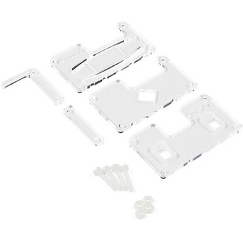
MI:pro Protector Case for micro:bit V2
SPARKFUN¥2,398税込¥2,6381個33日以内出荷Description。This MI:pro Protector Case for the BBC micro:bit has been designed to work with both the original micro:bit V1 and the micro:bit V2. These cases feature a four-layer construction style with ability to mount a 2xAAA battery pack to the back of the case while still providing access to all buttons and ports on the micro:bit. Though these cases do protect the micro:bit astoundingly well, the biggest benefit of using the MI:pro is to not accidentally short out the pads on the back of the micro:bit.。Construction is simple, requiring only a small flathead screwdriver(at most), and involves layering each plate on top of one another around the micro:bit and screwing it into place. Luckily, the MI:pro Protector case enables easy access to the edge pins at the bottom of the micro:bit, allowing it to still be plugged into an edge connector found on many of our carrier boards. The only board that cannot be used in conjunction with the MI:pro case is the SparkFun gamer:bit due to its edge connector being located in the center of the board.。Note:The MI:pro Protector case only includes the parts found in the Includes Tab. This case does。NOT。include a micro:bit, power source or mounting screws. These items will need to be purchased separately.。Features。Dimensions:Length:65mm.。Width:37mm.。Depth(without screws):12mm.。Depth(with screws):18.5mm.。Provides excellent protection to the BBC micro:bit whilst allowing access to the bottom pins.。Full access to the A and B buttons on the BBC micro:bit.。Attach a battery cage to the rear of the case with the supplied sticky fixer.。Full access to pins and connections including the micro USB connector.。Clear case material shows the on-board LEDs in perfect clarity.。The case is compatible with versions 1 and 2 of the micro:bit.。When used in conjunction with a battery holder, micro:bit projects can be fully mobile.アズワン品番67-0426-13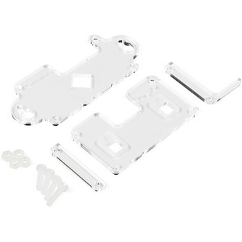
MI:pro Mountable Case for micro:bit V2
SPARKFUN¥1,998税込¥2,1981個33日以内出荷Description。The Mountable MI:pro is a simple and compact protective case for the micro:bit. This case has been specifically designed with portability and expansion in mind and is compatible with both the original micro:bit V1 and the micro:bit V2. These cases feature a three-layer construction style with ability to wall-mount the whole assembly onto any surface you want while still providing access to all buttons and ports on the micro:bit. Though these cases do feature wall-mountable tabs, the biggest benefit of using a case is to not accidentally short out the pads on the back of the micro:bit.。Construction is simple, requiring only a small flathead screwdriver, and involves layering each plate on top of one another around the micro:bit and screwing it into place. Luckily, the MI:pro case enables easy access to the edge pins at the bottom of the micro:bit, allowing it to still be plugged into an edge connector found on many of our carrier boards. The only board that cannot be used in conjunction with the MI:pro case is the SparkFun gamer:bit due to its edge connector being located in the center of the board.。Note:The MI:pro case only includes the parts found in the Includes Tab. This case does NOT include a micro:bit, power source or mounting screws. These items will need to be purchased separately.。Features。Dimensions:Length(minus the mounting brackets on the side):65mm.。Length(with the mounting brackets on the side):91mm.。Width:37mm.。Depth(without screws):9mm.。Depth(with screws):14mm.。Provides excellent protection to the BBC micro:bit whilst allowing access to the bottom pins.。Full access to the A and B buttons on the BBC micro:bit.。The mounting points allow you to fix the micro:bit to a surface for sturdy and more permanent installations.。Full access to pins and connections including the micro USB connector.。Clear case material shows the on-board LEDs in perfect clarity.。The case is compatible with versions 1 and 2 of the micro:bit.アズワン品番67-0426-14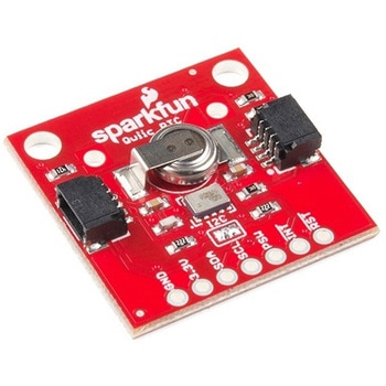
SparkFun Real Time Clock Module - RV-1805 Qwiic
SPARKFUN¥7,798税込¥8,5781個33日以内出荷Description。Get with the times, already! This SparkFun Real Time Clock(RTC)Module is a Qwiic-enabled breakout board for the RV-1805 chipset. The RTC is ultra-low power(running at only about 22nA in its lowest power setting)so it can use a supercapacitor for backup power instead of a normal battery. This means you get plenty of charge and discharge cycles without any degradation to the "battery." To make it even easier to get your readings, all communication is enacted exclusively via I2C, utilizing our handy Qwiic system so no soldering is required to connect it to the rest of your system. However, we still have broken out 0.1"-spaced pins in case you prefer to use a breadboard.。This RTC module's built in RV-1805 has not one, but two internal oscillators:a 32.768kHz tuning fork crystal and a low power RC based oscillator and can automatically switch between the two using the more precise crystal to correct the RC oscillator every few minutes. This feature allows the module to maintain a very accurate date and time with the worst case being +/- about three minutes over a year. The RV-1805 also has a built in trickle charger so as soon as the RTC is connected to power the it will be fully charged in under 10 minutes and has the ability to switch power to other systems allowing it to directly turn on or off a power hungry device such as a microcontroller or RF engine.。There is also the option to add a battery to the board if the supercapacitor just isn't going keep your project powered long enough(keep in mind, the supercap can hypothetically make the board keep time for around 35 days), you can solder on an external battery. That means you can let board sit with no power or connection to the outside world and the current hour/minute/second/date will be maintained.。Note:。The I2C address of the RV-1805 is 0x69 and is hardware defined. A multiplexer/Mux is required to communicate to multiple RV-1805 sensors on a single bus. If you need to use more than one RV-1805 sensor consider using the Qwiic Mux Breakout.。The SparkFun Qwiic connect system is an ecosystem of I2C sensors, actuators, shields and cables that make prototyping faster and less prone to error. All Qwiic-enabled boards use a common 1mm pitch, 4-pin JST connector. This reduces the amount of required PCB space, and polarized connections mean you can't hook it up wrong.。Get Started with the RV-1805 Real Time Clock Module Guide。Features。Operating Voltage(Startup):1.6V - 3.6V。Operating Voltage(Timekeeping):1.5V - 3.6V。Operating Temperature:-40℃ - 85℃。Time Accuracy:±2.0 ppm。Current Consumption:22nA(Typ.)。I2C Address:0xD2。Supercapacitor for Backup Power。2x Internal Oscillators。2x Qwiic Connectorsアズワン品番67-0420-02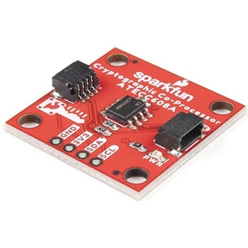
SparkFun Cryptographic Co-Processor Breakout - ATECC608A Qwiic
SPARKFUN¥1,498税込¥1,6481個33日以内出荷。Description。Product Restrictions:To access certain features of the ATECC608A, users will need to contact Microchip and sign an NDA contract to obtain the complete datasheet. Due to the required NDA - technical support, an Arduino library, and hookup guide are not provided for users on this product.。The SparkFun ATECC608A Cryptographic Co-processor Breakout allows you to add strong security to your IoT node, edge device, or embedded system. This includes。a。symmetric。authentication,。symmetric。AES-128 encryption/decryption, and much more. As stated above, the ATECC608A has limited Arduino support and the complete datasheet is under NDA with Microchip.。This breakout board includes two Qwiic ports for plug and play functionality. Utilizing our handy Qwiic system, no soldering is required to connect it to the rest of your system. However, we still have broken out 0.1"-spaced pins in case you prefer to use a breadboard. The ATECC608A chip is capable of many cryptographic processes, including, but not limited to:Creating and securely storing unique asymmetric key pairs based on Elliptic Curve Cryptography(FIPS186-3).。AES-128:Encrypt/Decrypt, Galois Field Multiply for GCM。Creating and verifying 64-byte digital signatures(from 32-bytes of message data).。Creating a shared secret key on a public channel via Elliptic Curve Diffie-Hellman Algorithm.。SHA-256 HMAC Hash including off-chip context save/restore。Internal high quality FIPS random number generator.。Embedded in the chip is a 10Kb EEPROM array that can be used for storing keys, certificates, data, consumption logging, and security configurations. Access to the sections of memory can then be restricted and the configuration locked to prevent changes. Each ATECC608A Breakout ships with a guaranteed unique 72-bit serial number and includes several security features to prevent physical attacks on the device itself, or logical attacks on the data transmitted between the device.。A summary datasheet for the ATECC608A is available here. The full datasheet is under NDA with Microchip. You will need to contact them for access to the entire datasheet. Meanwhile, the ArduinoATECCX08 Library currently only supports the ATECC608A with SAMD21 Arduino boards.。We do have much more support for the ATECC508A version of this chip. Please check out our ATECC508A Hookup Guide and Arduino Library(which includes six examples). This will get you familiar with the basics of elliptic curve cryptography and signing/verifying data with the ATECC508A version of the chip.。Note:The I2C address of the ATECC608A is 0x60 and is software-configurable to any address. A multiplexer/Mux is required to communicate to multiple ATECC608A sensors at the default address when on a single bus. If you need to use more than one ATECC608A sensor at the default address, consider using the Qwiic Mux Breakout.。Note:The ATECC608A can be only configured once before it is。PERMANENTLY。locked。. It is advisable that users purchase multiple boards in order to use other configurations and explore the advanced functions of the ATECC608A.。Additionally, this board。IS。capable of encrypting and decrypting data. However, to access these additional features, you will need to contact Microchip and sign an NDA contract to obtain the complete datasheet.。It is recommended that an SparkFun RedBoard Turbo - SAMD21 Development Board is used with this product due to the buffer size required on the I2C bus.。The SparkFun Qwiic Connect System is an ecosystem of I2C sensors, actuators, shields and cables that make prototyping faster and less prone to error. All Qwiic-enabled boards use a common 1mm pitch, 4-pin JST connector. This reduces the amount of required PCB space, and polarized connections mean you can't hook it up wrong.。。Features。Operating Voltage:2.0V-5.5V(。Default on Qwiic System:3.3V。)。Active Current Draw(for ATECC608A):16 mA。Sleep Current(for ATECC608A):<150 nA。Guaranteed Unique 72-bit Serial Number。10 Kb EEPROM Memory for Keys, Certificates, and Data。Storage for up to 16 Keys。256-bit Key Length。Internal High-Quality FIPS Random Number Generator(RNG)。Configurable I2C Address(7-bit):0x60(。Default。)アズワン品番67-0423-59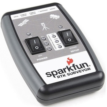
SparkFun RTK Surveyor
SPARKFUN¥129,800税込¥142,7801個33日以内出荷Description。The SparkFun RTK Surveyor is an easy to use GNSS receiver for centimeter-level positioning. Perfect for surveying, this preprogrammed device can also be used for autonomous driving, navigation, asset tracking and any other application where there is a clear view of the sky. The RTK Surveyor can also be used as a base station. With the flick of a switch, two RTK Surveyors can be used to create an RTK system capable of 14mm horizontal positional accuracy. The built-in Bluetooth(R)connection via an ESP32 WROOM enables the user to use the RTK Surveyor with their choice of GIS application on a phone or tablet. The built in battery allows field use for up to four hours and is compatible with common USB battery banks.。This device can be used in four modes:GNSS Positioning(~30cm accuracy)。GNSS Positioning with RTK(1.4cm accuracy)。GNSS Base Station。GNSS Base Station NTRIP Server。In Position mode the device receives L1/L2 signals from a user-provided antenna and the high-grade GNSS receiver provides lat/long and altitude with accuracies around 300mm.。In Positioning with RTK mode the device receives L1/L2 signals from the antenna and correction data from a base station. The correction data can be obtained from a cellular link to online correction sources or over a radio link to a 2nd RTK Surveyor setup as a base station.。In Base Station mode the device is mounted to a temporary position(like a tripod)and begins transmitting correction data over a radio or internet connection. A base is often used in conjunction with a second unit set to 'Positioning with RTK' to obtain the 14mm relative accuracy.。In Base Station NTRIP Server mode the device is mounted to a semi or permanently fixed position(like a roof)and connects over WiFi to transmit the correction data to a NTRIP caster so that any rover can access the correction data over a cellular or internet connection. This type of base is a very easy way to setup a very precise absolute correction source.。Two cables are provided with the RTK Surveyor allowing a user to plug on our easy to use Serial Telemetry Radios or their own radio link. If a local correction source is within 10km, a user can also use their phone to provide correction data over the Bluetooth(R)link(no external radio needed!).。Note:The SparkFun RTK Surveyor is just the enclosed device and does NOT include an antenna, serial telemetry radio, or associated mounting pieces. These items will need to be purchased separately from the Hookup Accessories below.。Get Started With the SparkFun RTK Surveyor Guide。Features。GNSS Receiver:ZED-F9P。Concurrent reception of GPS, GLONASS, Galileo and BeiDou。Receives both L1C/A and L2C bands。Current:68mA - 130mA(varies with constellations and tracking state)。Time to First Fix:25s(cold), 2s(hot)。Max Navigation Rate:PVT(basic location over UBX binary protocol)- 25Hz。RTK - 20Hz。Raw - 25Hz。Horizontal Position Accuracy:2.5m without RTK。0.010m with RTK。Max Altitude:50km(31 miles)。Max Velocity:500m/s(1118mph)。Bluetooth(R)Transceiver:ESP32 WROOM。Xtensa(R)dual-core 32-bit LX6 microprocessor。Up to 240MHz clock frequency。16MB of flash storage。520kB internal SRAM。Integrated 802.11 BGN WiFi transceiver。Integrated dual-mode Bluetooth(R)(classic and BLE)。Hardware accelerated encryption(AES, SHA2, ECC, RSA-4096)。2.5 μA deep sleep current。Overall Device。Internal Battery:LiPo 1000mAh with 500mA charging。Radio Port:3.3V TTL Serial(57600bps RTCM TX/RX)。Data Port:3.3V TTL Serial(115200bps NMEA)。Weight:132g(entire device including battery)。Dimensions:118mm×79mm×30mm(4.7in×3.1in×1.2in)。1x Qwiic Connector。1x microSD Socket for optional logging。Changes:This version(which replaces SPX-17369)uses a reinforced edge mount SMA connector for better resiliency when a fixed 'stub' antenna is used.アズワン品番67-0423-95