カテゴリ
- 学童・教育用品(26)
絞り込み
ブランド
- SPARKFUN
- 三菱電機(15)
- OGK KABUTO(オージーケーカブト)(13)
- ホンダ(11)
- RotopaX(ロトパックス)(11)
- ATG(10)
- DHA Corporation(10)
- Mitutoyo(ミツトヨ)(9)
- RS PRO(7)
- Baumer(6)
- メディアカバーマーケット(6)
- MAXZEN(5)
- StarTech.com(5)
- 富士電機(4)
- MouseComputer(4)
- SKF(日本エスケイエフ)(3)
- MAD MAX(マッドマックス)(3)
- ミツビシ(3)
- Seeed Studio(3)
- ブランドをもっと見る
「ut ax 4」の検索結果
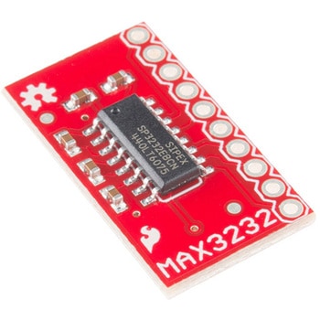
SparkFun Transceiver Breakout - MAX3232
SPARKFUN¥2,198税込¥2,4181個当日出荷仕様●項目1:組込み(完成機能)●項目2:インターフェース●項目4:レベル変換●項目5:MAX3232●項目8:RS232Cトランシーバーアズワン品番67-0452-36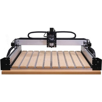
Shapeoko 4 XXL - Hybrid Table, No Router
SPARKFUN¥859,800税込¥945,7801個33日以内出荷Description。Please note, these machines are built to order have an estimated lead time of 4 business days before shipping。This is the Shapeoko 4 XXL, nearly double the cutting area of the Shapeoko 4 Standard! The Shapeoko is a 3-axis CNC Machine kアズワン品番67-0428-93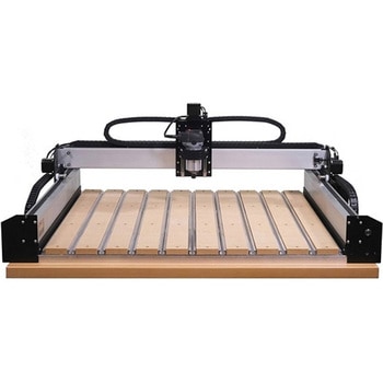
Shapeoko 4 XL - Hybrid Table, with Router
SPARKFUN¥799,800税込¥879,7801個33日以内出荷Description。Please note, these machines are built to order have an estimated lead time of 4 business days before shipping。This is the Shapeoko 4 XL, nearly double the cutting area of the Shapeoko 4 Standard! The Shapeoko is a 3-axis CNC Machine kit that allows you to create your 2D and 3D designs out of non-ferrous metals, hardwoods, and plastics. The Shapeoko 4 XL is designed to be affordable enough for any shop and powerful enough to do real work. Don't let the size intimidate you! This is an entry-level CNC machine designed for hobbyists, artists, and fabricators!。Each Shapeoko 4 XL has a cutting area of 838.2mm(X)x 444.5 mm(Y)x 101.6mm(Z)(33"×17.5"×4")and an overall footprint of 1270mm(X)x 609.6mm(Y)x 482.6mm(Z)(50"×24"×19"). The power cable included in this kit is designed for the United States National Plug Standard. Don't forget you can put whatever you want on the adapter ring(as long as it fits), whether that's a laser, 3D print extrusion head, or a marker. Get creative!。Upgrades from the Shapeoko 3 include:New, more rigid v-wheel design。15mm belts。Inductive homing switches。New electronics。Integrated t-slot Hybrid Table(OPTIONAL)。Fully-supported Y extrusions。Leadscrew-driven Z-axis。New, more rigid 65mm router mount。Sweepy 65mm V2 dust boot。Note:This item is non-returnable. If this item arrives damaged or is not functioning properly, please do not hesitate to contact us to see if further actions may be taken.。Not Compatible with the Shapeoko 4:Expansion Packs。T-Track Clamp Kits。Z-Plus。Proximity Switch Kit。Maintenance Kit。Shapeoko 3 Bit Setter。HDZ 4.0。。Features。Footprint:1270mm×609.6mm×482.6mm(50"×24"×19")。Cutting Area:838.2mm×444.5mm×101.6mm(33"×17.5"×4")。Weight 137lbs.。Operating System:Mac(OSX 10.14 or higher)or PC(Windows 8.1 or 10, Intel or AMD)アズワン品番67-0428-90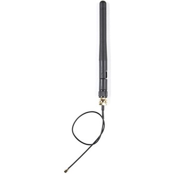
Raspberry Pi 4 Compute Module Antenna Kit
SPARKFUN¥5,598税込¥6,1581個33日以内出荷Description。This is the Antenna Kit for the Raspberry Pi 4 Compute Module wireless variants. The "duck" style antenna adds range to the wireless radio on the wireless enabled Compute Modules. Something quite desirable if you're working in industrial environments or other places a Compute Module would be used and the potential for signal interference is present. The antenna connects to the board via the press-fit U.FL connector on board the compute module(see photos for more details).。This kit contains an antenna, bulkhead fixture, and SMA to U.FL Cable.。Features。Frequency range:2400-2500/5100-5800 MHz。Bandwidth:100-700MHz。VSWR:≦ 2.0。Gain:2 dBi。Impedance:50 ohm。Polarisation:Vertical。Radiation:Omnidirectional。Maximum power:10W。Antenna dimensions:108 mm×10 mmアズワン品番67-0429-69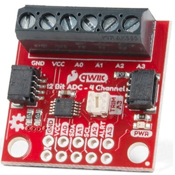
QWIIC 12BIT 4CHANNEL ADS1015
SPARKFUN¥5,498税込¥6,0481個33日以内出荷Description。A lot of the time you just need to add more analog inputs to solve a problem. It happens. The SparkFun Qwiic 12 Bit ADC can provide four channels of I2C controlled ADC input to your Qwiic enabled project. These channels can be used as single-ended inputs, or in pairs for differential inputs. What makes this even more powerful is that it has a programmable gain amplifier that lets you "zoom in" on a very small change in analog voltage(but will still effect your input range and resolution). Utilizing our handy Qwiic system, no soldering is required to connect it to the rest of your system. However, we still have broken out 0.1"-spaced pins in case you prefer to use a breadboard.。The ADS1015 uses its own internal voltage reference for measurements, but a ground and 3.3V reference are also available on the pin outs for users. This ADC board includes screw pin terminals on the four channels of input, allowing for solderless connection to voltage sources in your setup. It also has an address jumper that lets you choose one of four unique addresses(0x48, 0x49, 0x4A, 0x4B). With this, you can connect up to four of these on the same I2C bus and have sixteen channels of ADC. The maximum resolution of the converter is 12-bits in differential mode and 11-bits for single-ended inputs. Step sizes range from 125μV per count to 3mV per count depending on the full-scale range(FSR)setting.。We have included an onboard 10K trimpot connected to channel A3. This is handy for initial setup testing and can be used as a simple variable input to your project. But don't worry, we added an isolation jumper so you can use channel A3 however you'd like.。Note:The I2C address of the ADS1015 is 0x48 and is jumper selectable to 0x49, 0x4A, 0x4B. A multiplexer/Mux is required to communicate to multiple ADS1015 sensors on a single bus. If you need to use more than one ADS1015 sensor consider using the Qwiic Mux Breakout.。The SparkFun Qwiic connect system is an ecosystem of I2C sensors, actuators, shields and cables that make prototyping faster and less prone to error. All Qwiic-enabled boards use a common 1mm pitch, 4-pin JST connector. This reduces the amount of required PCB space, and polarized connections mean you can't hook it up wrong.。Get Started with the SparkFun Qwiic 12-Bit ADC Hookup Guide。Features。ADS1015。Operating Voltage(VDD):2.0V-5.5V。(Note:When powering with a Qwiic cable, the input range is only 3.3v)。Operating Temperature:-40℃ to 125℃。Operation Modes:Single-Shot, Continuous-Conversion(Default), and Duty Cycling。Analog Inputs:Measurement Type:Single-Ended(Default)。Input Voltage Range:GND to VDD。Full Scale Range(FSR):±.256V to ±6.114V(Default:2.048V)。Resolution:12-bit(Differential)or 11-bit(Single-Ended)。LSB size:0.125mV - 3mV(Default:1 mV)。Sample Rate:128 Hz to 3.3 kHz(Default:1600SPS)。Current Consumption(Typical):150μA-200μA。I2C Address:0x48(Default), 0x49, 0x4A, or 0x4B。Screw pin terminals for solderless connection to voltage sources。Four unique I2C addresses:0x48。0x49。0x4A。0x4B。2x Qwiic connection ports。Onboard 10K trimpotアズワン品番67-0360-13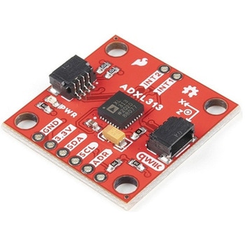
SparkFun Triple Axis Digital Accelerometer Breakout - ADXL313 Qwiic
SPARKFUN¥6,698税込¥7,3681個33日以内出荷Description。The SparkFun ADXL313 Breakout is a low power, high resolution(up to 13-bits)3-axis accelerometer for measurement up to ±4g. This breakout measures the static acceleration of gravity in tilt-sensing applications, as well as dynamic accelアズワン品番67-0427-42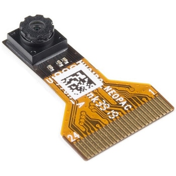
Himax CMOS Imaging Camera - HM01B0
SPARKFUN¥3,698税込¥4,0681個33日以内出荷。Description。The HM01B0 from Himax Imaging is an ultra low power CMOS Monochrome Image Sensor that enables the integration of an "Always On" camera for computer vision applications such as gestures, intelligent ambient light and proximity sensing, tracking and object identification. The sensor allows the sensor to consume very low power of <2mW at QVGA 30FPS. This low power consumption and vision applications camera comes with a ribbon cable that mates to the camera connector populated on the following products:MicroMod Machine Learning Carrier Board。Artemis Development Kit。Edge Development Board - Apollo3 Blue。The HM01B0 contains 320×320 pixel resolution and supports a 320×240 window mode which can be readout at a maximum frame rate of 60FPS, and a 2×2 monochrome binning mode with a maximum frame rate of 120FPS. The video data is transferred over a configurable 1bit, 4bit or 8bit interface with support for frame and line synchronization. The sensor integrates black level calibration circuit, automatic exposure and gain control loop, self-oscillator and motion detection circuit with interrupt output to reduce host computation and commands to the sensor to optimize the system power consumption.。Features。Image Sensor。Ultra Low Power Image Sensor(ULPIS)designed for Always On vision devices and applications。High sensitivity 3.6μ BrightSenseTM pixel technology。320×320 active pixel resolution with support for QVGA window, vertical flip and horizontal mirror readout。Programmable black level calibration target, frame size, frame rate, exposure, analog gain(up to 8x)and digital gain(up to 4x)。Automatic exposure and gain control loop with support for 50 / 60Hz flicker avoidance。Flexible 1bit, 4bit and 8bit video data interface with video frame and line sync。Motion Detection circuit with programmable ROI and detection threshold with digital output to serve as an interrupt。On-chip self oscillator。I2C 2-wire serial interface for register access。High CRA for low profile module design。Sensor Parameters。Active Pixel Array 320×320。Pixel Size 3.6 μm×3.6 μm。Full Image Area 1152 μm×1152 μm。Diagonal(Optical Format)1.63 mm(1/11″)。Scan Mode:Progressive。Shutter Type:Electronic Rolling Shutter。Frame Rate MAX 51 fps @ 320×320, 60 fps @ 320×240(QVGA)。CRA(maximum)30℃。Sensor Specifications。Supply Voltage:Analog - 2.8 V, Digital - 1.5V(Internal LDO:1.5V - 2.8V), I/O - 1.5 - 2.8V。Input Reference Clock:3 - 50 MHz。Serial Interface(I2C):2-wire, 400 KHz max.。Video Data Interface:1b, 4b, 8b with frame / line SYNC。Output Clock Rate MAX:50 MHz for 1bit, 12.5 MHz for 4bit, 6.25 MHz for 8bit。Est. Power Consumption(include IO with 5pF load):QVGA 60FPS(Typical)<4 mW。QVGA 30FPS(Typical)<2 mWアズワン品番67-0427-08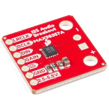
SparkFun I2S Audio Breakout - MAX98357A
SPARKFUN¥1,998税込¥2,1981個33日以内出荷Description。The SparkFun I2S Audio Breakout board uses the MAX98357A digital to analog converter(DAC), which converts I2S(not be confused with I2C)audio to an analog signal to drive speakers. The I2S Audio Breakout converts the digital audio signals using the I2S standard to an analog signal and amplifies the signal using a class D amplifier which can deliver up to 3.2W of power into a 4Ω load. The board can be configured to output only the left channel audio, right channel, or both.。The SparkFun I2S Audio Breakout board is fairly simple, requiring only a few pin connections to get it up and working. By default the board is configured in "mono" operation, meaning the left and right signals are combined together to drive a single speaker. If you want a separate speaker for the left and right audio channels you'll need to cut the mono jumper. In addition to being able to select the audio channel output, the gain can also be configured in a few ways. The gain of the amplifier can be configured from as low as +3dB to as high as +15dB. While the channel selection can be configured on board, the gain however is controlled externally using the gain pin. By default, the board is configured for +9dB, but can be easily changed!。Get Started with the SparkFun I2S Audio Breakout Guide。Features。Supply Voltage Range:2.5V - 5.5V.。Output Power:3.2W into 4Ω at 5V.。Output Channel Selection:Left, Right, or Left/2 + Right/2(Default).。Sample Rate:8kHz - 96kHz.。Sample Resolution:16/32 bit.。Quiescent Current:2.4mA.。Filterless Class D Outputs。No MCLK Required。Click and Pop Reduction。Short-Circuit and Thermal Protection.アズワン品番67-0422-64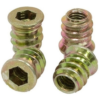
Threaded Inserts Qty 100 - Inch
SPARKFUN¥6,198税込¥6,8181個33日以内出荷Description。These inserts are great for easy and flexible work holding solutions. You could strategically place a few to hold down material in a jig or fixture, or install in a grid pattern to turn your wasteboard into a threaded table by installing these threaded inserts.。Installation is easy, simply create a 9mm pilot hole, then thread the insert into the hole.。Both the inch and metric come in packs of 100 inserts and include a 6mm hex key and 6mm hex driver for installation. The hex driver can be used with a cordless drill for quick installation.。Features。6mm Hex(on both Imperial and Metric versions)。Length:13mm(~1/2")。Maximum Hole Size:9mm(0.354", Letter T Drill)。1/4-20 threadアズワン品番67-0429-10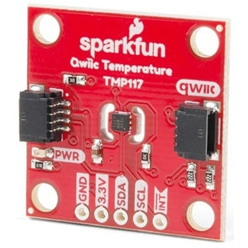
SparkFun High Precision Temperature Sensor - TMP117 Qwiic
SPARKFUN¥4,898税込¥5,3881個33日以内出荷。Description。The SparkFun Qwiic TMP117 breakout is a high precision temperature sensor equipped with an I2C interface. It outputs temperature readings with high precision of ±0.1℃ across the temperature range of -20℃ to +50℃s with no calibration and a maximum range from -55℃ to 150℃. The SparkFun High Precision Temperature Sensor also has a very low power consumption rate which minimizes the impact of self-heating on measurement accuracy. Utilizing our handy Qwiic system, no soldering is required to connect it to the rest of your system. However, we still have broken out 0.1"-spaced pins in case you prefer to use a breadboard.。The SparkFun High Precision Temperature Sensor also includes programmable temperature limits, and digital offset for system correction. While the TMP102 is capable of reading temperatures to a resolution of 0.0625℃ and is accurate up to 0.5℃, the on-board TMP117 is not only more precise but has a 16-bit resolution of 0.0078℃!。To make this breakout even easier to use, we've written an Arduino library to help you get started "Qwiic-ly." Check the Documents tab above for more information.。The SparkFun Qwiic Connect System is an ecosystem of I2C sensors, actuators, shields and cables that make prototyping faster and less prone to error. All Qwiic-enabled boards use a common 1mm pitch, 4-pin JST connector. This reduces the amount of required PCB space, and polarized connections mean you can't hook it up wrong.。The TMP117 High Precision Temperature Sensor can also be automatically detected, scanned, configured, and logged using the OpenLog Artemis datalogger system. No programming, soldering, or setup required!。Need a custom board? This component can be found in SparkFun's A La Carte board builder. You can have a custom design fabricated with this component - and your choice of hundreds of other sensors, actuators and wireless devices - delivered to you in just a few weeks.。Get Started with the SparkFun High Precision TMP117 Hookup Guide。Features。Uses I2C interface(Qwiic-enabled)。Four selectable addresses。0x48(default), 0x49, 0x4A, 0x4B。16-bit resolution, 0.0078℃。High accuracy, digital temperature sensor。±0.1℃(max)from ?20℃ to 50℃。±0.15℃(max)from ?40℃ to 70℃。±0.2℃(max)from ?40℃ to 100℃。±0.25℃(max)from ?55℃ to 125℃。±0.3℃(max)from ?55℃ to 150℃。Operating temperature range。-55℃ to +150℃。Operating voltage range。1.8V to 5.5V。Typically 3.3V if using the Qwiic cable。Low power consumption。3.5μA(1-Hz conversion cycle)。150nA(shutdown current)。Programmable operating modes。Continuous, one-shot, and shutdown。Programmable temperature alert limits。Selectable averaging for reduced noise。Digital offset for system correction。NIST traceability。。Documents。Schematic。Eagle Files。Board Dimensions。Hookup Guide。Datasheet(TMP117)。Arduino Library。GitHub Hardware Repoアズワン品番67-0427-10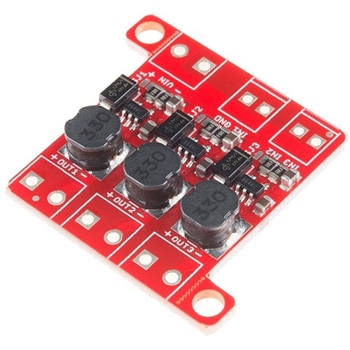
PicoBuck LED Driver
SPARKFUN¥5,298税込¥5,8281個33日以内出荷Description。The PicoBuck LED Driver is an economical and easy to use driver that will allow you to control and blend three different LEDs on three different channels. By default, each channel is driven at 330mA; that current can be reduced by either presenting an analog voltage or a PWM signal to the board. Version 12 of the board adds a solderable jumper that can be closed to increase the maximum current to 660mA. The new voltage regulator also increased the voltage rating on the various components on the board, allowing it to be used up to the full 36V rating of the AL8805 part.。Three signal inputs are provided for dimming control. You can use the PWM signal from an Arduino or your favorite microcontroller to dim each channel individually, or you can tie them all to the same PWM for simultaneous dimming. Dimming can be done by an analog voltage(20%-100% of max current by varying voltage from .5V-2.5V)or by PWM(so long as PWM minimum voltage is less than .4V and maximum voltage is more than 2.4V)for a full 0-100% range. A small jumper is provided for each channel to allow you to increase the drive strength from 330mA to 660mA. Two mounting holes for 4-40 or M3 screws are provided on either side of the board. They are perforated so they can be easily snapped off with a pair of pliers, if a smaller footprint is desired.。Note:。If you're going to use screw terminals, this board uses two different sizes. Check the related products for both sizes you'll need.。Note:。The PicoBuck LED Driver was made in collaboration with Ethan Zonca. A portion of each sale is given back to him.アズワン品番67-0420-83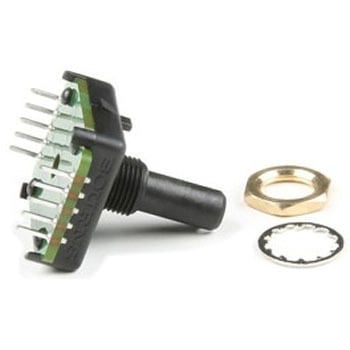
Bourns Absolute Encoder EAW0J-B24-AE0128L
SPARKFUN¥3,500税込¥3,8501個33日以内出荷。Description。The Bourns Absolute Encoder is a digital control knob that provides 128 unique results evenly spaced around a full circle. It is designed as a control panel knob but can be adapted for other uses. This can be a good alternative to using a potentiometer and analog pin, as this allows for full-turn and multi-turn operation.。It differs from the more common incremental rotary encoder which has only two or four values in a rotation and is designed to measure full rotations and direction. This measures。angles。and absolute position is maintained between power cycles.。Features。128 rotary positions。360 degree continuous rotation。Rotational life - 50,000 revolutions(min)。Max RPM - up to 120。Absolute digital output will retain its last position between power cycles or in the event of a power failure。Threaded M9x0.75 in. bushing。3/4 in. rotating encoder shaft。Rear mount terminalsアズワン品番67-0421-27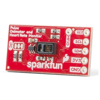
SparkFun Pulse Oximeter and Heart Rate Sensor - MAX30101 & MAX32664 Qwiic
SPARKFUN¥13,980税込¥15,3781個33日以内出荷Description。The SparkFun Pulse Oximeter and Heart Rate Sensor is an I2C based biometric sensor, utilizing two chips from Maxim Integrated:the MAX32664 Biometric Sensor Hub and the MAX30101 Pulse Oximetry and Heart Rate Module. While the latter does all the sensing, the former is an incredibly small and fast Cortex M4 processor that handles all of the algorithmic calculations, digital filtering, pressure/position compensation, advanced R-wave detection, and automatic gain control. We've provided a Qwiic connector to easily connect to the I2C data lines but you will also need to connect to two additional lines. This board is very small, measuring at 1in×0.5in(25.4mm×12.7mm), which means it will fit nicely on your finger without all the bulk.。The MAX30101 does all the sensing by utilizing its internal LEDs to bounce light off the arteries and arterioles in your finger's subcutaneous layer and sensing how much light is absorbed with its photodetectors. This is known as photoplethysmography. This data is passed onto and analyzed by the MAX32664 which applies its algorithms to determine heart rate and blood oxygen saturation(SpO2). SpO2 results are reported as the percentage of hemoglobin that is saturated with oxygen. It also provides useful information such as the sensor's confidence in its reporting as well as a handy finger detection data point. To get the most out of the sensor we've written an Arduino Library to make it easy to adjust all the possible configurations.。The SparkFun Qwiic connect system is an ecosystem of I2C sensors, actuators, shields and cables that make prototyping faster and less prone to error. All Qwiic-enabled boards use a common 1mm pitch, 4-pin JST connector. This reduces the amount of required PCB space, and polarized connections mean you can't hook it up wrong.。Get Started with the Pulse Oximeter and Heart Rate Monitor Hookup Guide。Features。SparkFun Pulse Oximeter and Heart Rate Sensor。MAX30101 and MAX32664 sensor and sensor hub。Qwiic connectors for power and I2C interface。I2C Address:0x55。MAX30101 - Pulse Oximeter and Heart-Rate Sensor。Heart-Rate Monitor and Pulse Oximeter Sensor in LED Reflective Solution。Integrated Cover Glass for Optimal, Robust Performance。Ultra-Low Power Operation for Mobile Devices。Fast Data Output Capability。Robust Motion Artifact Resilience。MAX32664 - Ultra-Low Power Biometric Sensor Hub。Biometric Sensor Hub Solution。Finger-Based Algorithms Measure Pulse Heart Rate and Pulse Blood Oxygenation Saturation(SpO2)。Both Raw and processed data are available。Basic Peripheral mix optimizes size and performanceアズワン品番67-0426-96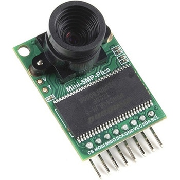
Arducam 5MP Plus OV5642 Mini Camera Module
SPARKFUN¥23,980税込¥26,3781個33日以内出荷Description。The Arducam 5MP Plus OV5642 Mini provides an easy to use camera solution for those working with low-cost microcontrollers such as those used with Arduino and the RP2040 from Raspberry Pi. It's a general purpose 5MP camera module that's SPI enabled reducing the complexity of controlling the camera. It's a step up in performance from it's predecessor, the Arducam-M-5MP. The most impressive aspect being that it's possible to control more than one of these from the same microcontroller. It features a M12 mount or CS-Mount lens holder with the ability to change lenses. Best of all, there's code libraries for Arduino, STM32, Chipkit, Raspberry Pi, and BeagleBone Black.。The Arducam 5MP Plus OV5642 Mini supports JPEG compression mode, single and multiple shoot mode, short movie recording, one-time capture multiple read operation, burst read operation, and low power mode.。Features。Power supply 3.3V~5V。Active array size:2592×1944。SPI speed:Max 8MHz。Shutter:rolling shutter。Frame buffer:8MByte。Pixel Size:1.4μm×1.4μm。Default M12 Lens:55°。Resolution support:5MP, 1080p, 720p, VGA, QVGA。Format support:RAW, YUV, RGB, JPEG。Size:34×24 mm。Weight:20g。Temperature Range:-10℃~+55℃。Lens Specification:sensor size:1/4″; EFL:4.9mm; F/N:2.2; BFL:1.2mm; HFOV:60 degree(SKU:U6067)アズワン品番67-0423-65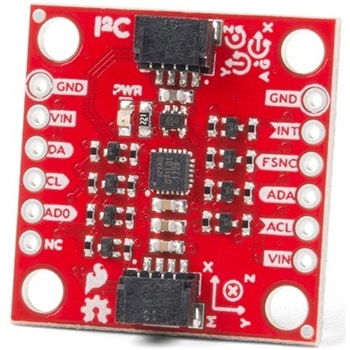
SparkFun 9DoF IMU Breakout - ICM-20948 Qwiic
SPARKFUN¥7,298税込¥8,0281個33日以内出荷。Description。The SparkFun 9DoF IMU Breakout incorporates all the amazing features of Invensense's ICM-20948 into a Qwiic-enabled breakout board complete with a logic shifter and broken out GPIO pins for all your motion sensing needs. The ICM-20948 itself is an extremely low powered, I2C and SPI enabled 9-axis motion tracking device that is ideally suited for smartphones, tablets, wearable sensors, and IoT applications. Utilizing our handy Qwiic system, no soldering is required to connect it to the rest of your system. However, we still have broken out 0.1"-spaced pins in case you prefer to use a breadboard.。In addition to the 3-Axis Gyroscope with four selectable ranges, 3-Axis Accelerometer, again with four selectable ranges, and 3-axis magnetometer with an FSR to ±4900μT, the ICM-20948 also includes a Digital Motion Processor that offloads the computation of motion sensing algorithms from the detectors, allowing optimal performance of the sensors. We've also broken out all the ICM-20948 pin functionality to GPIO and labeled them I2C on the front, SPI on the back for ease of identification.。Note:The I2C address of the ICM-20948 is 0x69 and is jumper selectable to 0x68. A multiplexer/Mux is required to communicate to multiple ICM-20948 sensors on a single bus. If you need to use more than one ICM-20948 sensor consider using the Qwiic Mux Breakout.。The SparkFun Qwiic Connect System is an ecosystem of I2C sensors, actuators, shields and cables that make prototyping faster and less prone to error. All Qwiic-enabled boards use a common 1mm pitch, 4-pin JST connector. This reduces the amount of required PCB space, and polarized connections mean you can't hook it up wrong.。Need a custom board? This component can be found in SparkFun's A La Carte board builder. You can have a custom design fabricated with this component - and your choice of hundreds of other sensors, actuators and wireless devices - delivered to you in just a few weeks.。Get Started with the SparkFun ICM-20948 9DoF IMU Guide。Features。1.95 V to 3.6 V supply voltage。Triple-axis MEMS gyroscope with user-programmable full-scale range of ±250 dps, ±500 dps, ±1000 dps, and ±2000 dps。Triple-axis MEMS accelerometer with programmable full scale range of ±2g, ±4g, ±8g, and ±16g。Triple-axis silicon monolithic Hall-effect magnetic sensor with full scale measurement range to ±4900 μT。I2C at up to 100 kHz(standard-mode)or up to 400 kHz(fast-mode)or SPI at up to 7 MHz for communicationwith registers。On-board digital motion processor(DMP)。Digital-output temperature sensor。2x Qwiic Connection Ports。I2C Address:0x69(0x68 with Jumper)。。Documents。Schematic。Eagle Files。Hookup Guide。Datasheet(ICM-20948)。Arduino Library。Python Support(Qwiic_Py)。GitHub Hardware Repoアズワン品番67-0427-05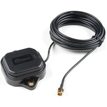
Multi-Band Magnetic MountAntenna-5m
SPARKFUN¥33,980税込¥37,3781個33日以内出荷Description。The ANN-MB-00 GNSS multiband antenna is extremely unique from other GNSS/GPS antennas in that it is designed to receive both the classic L1 GPS band and the newly launched(started in 2005)L2 GPS band. Additionally, the ANN-MB-00 from u-blox is extremely well built with both a magnetic base with mounting holes for additional anchoring for the harshest environments.。Designed for the latest u-blox F9 platform--including the ZED-F9P module--it provides a fast, easy, and reliable multi-band antenna solution but can be used with any GPS/GNSS receiver that can benefit from the L1/L2 dual reception.。This antenna supports GPS, GLONASS, Galileo, and BeiDou and includes a high-performance multi-band RHCP dual-feed patch antenna element, a built-in high-gain LNA with SAW pre-filtering, and a 5m SMA cable.。Features。Frequency:L1 Band:1559-1606MHz。L2/L5 Band:1197-1249MHz。Peak gain(over 15cm diameter ground plane):L1 Band:3.5dBic。L2/L5 Band:0-2.0dBic。VSWR:max. 2。Bandwidth:min. 200MHz。Impedance:50 Ohm。Polarization RHCP。Supports GPS, GLONASS, Galileo, and BeiDou。5m coaxial cable with SMA connector。Magnetic base, fixed installation option(screw mount, 2×M4 screws)。Dimensions:60.0mm×82.0mm×22.5mm。Weight:175g(including cable)アズワン品番67-0372-23
SparkFun Breadboard Power Supply 5V/3.3V
SPARKFUN¥3,998税込¥4,3981個33日以内出荷Here is a very simple breadboard power supply kit that takes power from a DC wall wart and outputs a selectable 5V or 3.3V regulated voltage. The .1" headers are mounted on the bottom of the PCB for simple insertion into a breadboard. Pins labeled VCC and GND plug directly into the power lines. The lone pair of pins have no electrical connection but help support the PCB.。There are two pins available within the barrel jack footprint. Any stripped +/- DC supply can be connected instead of the barrel connector. Board has both an On/Off switch and a voltage select switch(3.3V/5V).。Comes as a bag of parts kit and is easily assembled if you can follow the silkscreen indicators and have beginning experience with a soldering iron. You will need to read the resistor bands or use a multimeter to determine the resistor sizes.。Dimensions:1.25x1.25"。Kit Includes:DC Barrel Connector(2.1mm center positive)。TO-220 Voltage Regulator(LM317 1.5A max current)。1N4004 Reverse Protection Diode。100uF 25V Capacitor。10uF 25V Capacitor。0.1uF 50V Capacitor。Red Power LED - High Brightness。2×SPDT Slide Switch。4×0.1" Header Pins。2×330 Resistor 1/6W。390 Resistor 1/6W。240 Resistor 1/6W。Bare PCB with Silkscreen Indicators。PTC resettable fuse仕様●項目1:組込み(組立てキット)●項目2:電源●項目4:リニア電源●項目8:ブレッドボード用電源アズワン品番67-0454-01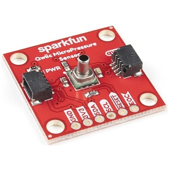
SparkFun Qwiic MicroPressure Sensor
SPARKFUN¥24,980税込¥27,4781個33日以内出荷Description。The SparkFun Qwiic MicroPressure Sensor is a miniature breakout equipped with Honeywell's 25psi piezoresistive silicon pressure sensor. This MicroPressure Sensor offers a calibrated and compensated pressure sensing range of 60mbar to 2.5bar, easy to read 24 bit digital I2C output, and can be calibrated and compensated over a specific temperature range for sensor offset, sensitivity, temperature effects, and non-linearity using an on-board Application Specific Integrated Circuit(ASIC). With its ultra-low power consumption and Qwiic ports, you've got yourself a power packed little sensor!。Each Qwiic MicroPressure Sensor has a calibrated pressure sensing range from 1-25psi and a power consumption rate as low as 0.01mW typ. average power, 1Hz measurement frequency for ultimate portability. Used in multiple medical(blood pressure monitoring, negative pressure wound therapy), industrial(air braking systems, gas and water meters), and consumer uses(coffee machines, humidifiers, air beds, washing machines, dishwashers), the SparkFun Qwiic MicroPressure Sensor is a great addition to the SparkFun Qwiic ecosystem!。The SparkFun Qwiic Connect System is an ecosystem of I2C sensors, actuators, shields and cables that make prototyping faster and less prone to error. All Qwiic-enabled boards use a common 1mm pitch, 4-pin JST connector. This reduces the amount of required PCB space, and polarized connections mean you can't hook it up wrong.。Get Started with the SparkFun Qwiic MicroPressure Hookup Guide。Features。Pressure Type:Absolute。Operating Pressure:25psi(172.37kPa)。I2C Address:0x18。Accuracy:±0.25%。Voltage - Supply:1.8V-3.6V。Port Size:Male - 0.1"(2.5mm)Tube。Port Style:Barbless。Maximum Pressure:60psi(413.69kPa)。Compatible with a variety of liquid media。2x Qwiic Connectorsアズワン品番67-0427-25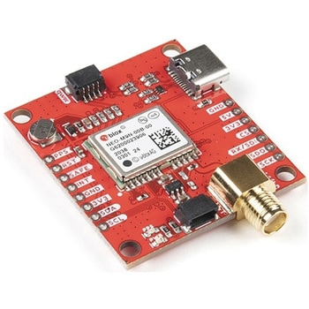
SparkFun GPS Breakout - NEO-M9N, SMA Qwiic
SPARKFUN¥22,980税込¥25,2781個33日以内出荷Description。The SparkFun NEO-M9N GPS Breakout is a high quality GPS board with equally impressive configuration options including SMA. The NEO-M9N module is a 92-channel u-blox M9 engine GNSS receiver, meaning it can receive signals from the GPS, GLONASS, Galileo, and BeiDou constellations with ~1.5 meter accuracy. This breakout supports concurrent reception of four GNSS. This maximizes position accuracy in challenging conditions increasing, precision and decreases lock time; and thanks to the onboard rechargeable battery, you'll have backup power enabling the GPS to get a hot lock within seconds! Additionally, this u-blox receiver supports I2C(u-blox calls this Display Data Channel)which makes it perfect for the Qwiic compatibility so we don't have to use up our precious UART ports. Utilizing our handy Qwiic system, no soldering is required to connect it to the rest of your system. However, we still have broken out 0.1"-spaced pins in case you prefer to use a breadboard.。The NEO-M9N module detects jamming and spoofing events and can report them to the host, so that the system can react to such events. A SAW(Surface Acoustic Wave)filter combined with an LNA(Low Noise Amplifier)in the RF path is integrated into the NEO-M9N module which allows normal operation even under strong RF interferences.。U-blox based GPS products are configurable using the popular, but dense, windows program called u-center. Plenty of different functions can be configured on the NEO-M9N:baud rates, update rates, geofencing, spoofing detection, external interrupts, SBAS/D-GPS, etc. All of this can be done within the SparkFun Arduino Library!。The SparkFun NEO-M9N GPS Breakout is also equipped with an on-board rechargeable battery that provides power to the RTC on the NEO-M9N. This reduces the time-to-first fix from a cold start(~24s)to a hot start(~2s). The battery will maintain RTC and GNSS orbit data without being connected to power for plenty of time.。This product requires an antenna:Be sure to check out the related products/hookup accessories and pick a suitable SMA antenna for your project.。The SparkFun Qwiic Connect System is an ecosystem of I2C sensors, actuators, shields and cables that make prototyping faster and less prone to error. All Qwiic-enabled boards use a common 1mm pitch, 4-pin JST connector. This reduces the amount of required PCB space, and polarized connections mean you can't hook it up wrong.。The NEO-M9N GPS Breakout can also be automatically detected, scanned, configured, and logged using the OpenLog Artemis datalogger system. No programming, soldering, or setup required!。Get Started With the SparkFun NEO-M9N GPS Guide。Features。Integrated SMA connector for use with antenna of your choice。92-Channel GNSS Receiver。1.5m Horizontal Accuracy。25Hz Max Update Rate(four concurrent GNSS)。Time-To-First-Fix:Cold:24s。Hot:2s。Max Altitude:80,000m。Max G:≦4。Max Velocity:500m/s。Velocity Accuracy:0.05m/s。Heading Accuracy:0.3 degrees。Time Pulse Accuracy:30ns。3.3V VCC and I/O。Current Consumption:~31mA Tracking GPS+GLONASS。Software Configurable。Geofencing。Odometer。Spoofing Detection。External Interrupt。Pin Control。Low Power Mode。Many others!。Supports NMEA, UBX, and RTCM protocols over UART or I2C interfacesアズワン品番67-0423-87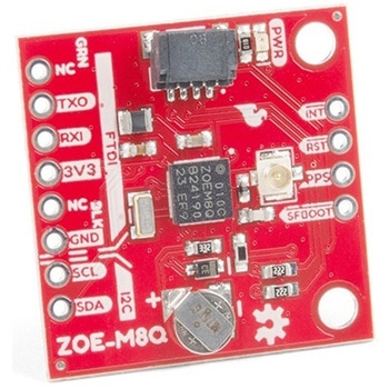
SparkFun GPS Breakout - ZOE-M8Q Qwiic
SPARKFUN¥14,980税込¥16,4781個33日以内出荷Description。The SparkFun ZOE-M8Q GPS Breakout is a high accuracy, miniaturized, GPS board that is perfect for applications that don't possess a lot of space. The on-board ZOE-M8Q is a 72-channel GNSS receiver, meaning it can receive signals from the GPS, GLONASS, BeiDou, and Galileo constellations. This increases precision and decreases lock time and thanks to the onboard rechargable battery you'll have backup power enabling the GPS to get a hot lock within seconds! Additionally, this u-blox receiver supports I2C(u-blox calls this Display Data Channel)which made it perfect for the Qwiic compatibility so we don't have to use up our precious UART ports. Utilizing our handy Qwiic system, no soldering is required to connect it to the rest of your system. However, we still have broken out 0.1"-spaced pins in case you prefer to use a breadboard.。U-blox based GPS products are configurable using the popular, but dense, windows program called u-center. Plenty of different functions can be configured on the ZOE-M8Q:baud rates, update rates, geofencing, spoofing detection, external interrupts, SBAS/D-GPS, etc. All of this can be done within the SparkFun Arduino Library. We've also made sure to configure the UART pin grouping on the breakout to an industry standard to insure that it easily connects to a Serial Basic.。The SparkFun ZOE-M8Q GPS Breakout is also equipped with an on-board rechargeable battery that provides power to the RTC on the ZOE-M8Q. This reduces the time-to-first fix from a cold start(~30s)to a hot start(~1s). The battery will maintain RTC and GNSS orbit data without being connected to power for up to five hours. Since the ZOE-M8Q is a tiny GPS receiver and to minimize its footprint, we've added a U.FL connector to allow the use of both large standard ceramic antennas as well as very small chip scale antennas.。Note:The I2C address of the ZOE-M8Q is 0x42 and is software configurable. A multiplexer/Mux is required to communicate to multiple ZOE-M8Q sensors on a single bus. If you need to use more than one ZOE-M8Q sensor consider using the Qwiic Mux Breakout.。The SparkFun Qwiic Connect System is an ecosystem of I2C sensors, actuators, shields and cables that make prototyping faster and less prone to error. All Qwiic-enabled boards use a common 1mm pitch, 4-pin JST connector. This reduces the amount of required PCB space, and polarized connections mean you can't hook it up wrong.。The ZOE-M8Q GPS Breakout can also be automatically detected, scanned, configured, and logged using the OpenLog Artemis datalogger system. No programming, soldering, or setup required!。Get Started With the SparkFun ZOE-M8Q Hookup Guide。Features。72-Channel GNSS Receiver。2.5m Horizontal Accuracy。18Hz Max Update Rate。Time-To-First-Fix:Cold:26s。Hot:1s。Max Altitude:50,000m。Max G:≦4。Max Velocity:500m/s。Velocity Accuracy:0.05m/s。Heading Accuracy:0.3 degrees。Time Pulse Accuracy:30ns。3.3V VCC and I/O。Current Consumption:~29mA Tracking GPS+GLONASS。Software Configurable。Geofencing。Odometer。Spoofing Detection。External Interrupt。Pin Control。Low Power Mode。Many others!。Supports NMEA, UBX, and RTCM protocols over UART or I2C interfacesアズワン品番67-0423-76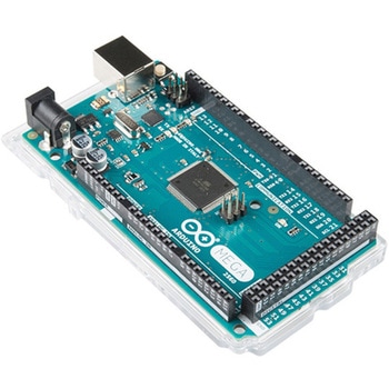
ArduinoMega 2560 R3
SPARKFUN¥18,980税込¥20,8781個33日以内出荷。Description。Arduino is an open-source physical computing platform based on a simple i/o board and a development environment that implements the Processing/Wiring language. Arduino can be used to develop stand-alone interactive objects or can be connected to software on your computer(e.g. Flash, Processing, MaxMSP). The open-source IDE can be downloaded for free(currently for Mac OS X, Windows, and Linux).。The Arduino Mega is a microcontroller board based on the ATmega2560. It has 54 digital input/output pins(of which 14 can be used as PWM outputs), 16 analog inputs, 4 UARTs(hardware serial ports), a 16 MHz crystal oscillator, a USB connection, a power jack, an ICSP header, and a reset button. It contains everything needed to support the microcontroller; simply connect it to a computer with a USB cable or power it with a AC-to-DC adapter or battery to get started.。Never fear for accidental electrical discharge, either since since the Mega also includes a plastic base plate to protect it!。The Mega 2560 R3 also adds SDA and SCL pins next to the AREF.。In addition, there are two new pins placed near the RESET pin. One is the IOREF that allow the shields to adapt to the voltage provided from the board.。The other is a not connected and is reserved for future purposes.。The Mega 2560 R3 works with all existing shields but can adapt to new shields which use these additional pins.。Not sure which Arduino or Arduino-compatible board is right for you? Check out our Arduino Buying Guide!。Features。ATmega2560 microcontroller。Input voltage - 7-12V。54 Digital I/O Pins(14 PWM outputs)。16 Analog Inputs。256k Flash Memory。16Mhz Clock Speedアズワン品番67-0349-13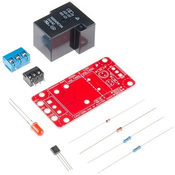
SparkFun Beefcake Relay Control Kit Ver. 2.0
SPARKFUN¥3,198税込¥3,5181個33日以内出荷Description。Your 5V system can wield great power with this big, beefy relay board. How does 10A on the NC contacts and 20A on the NO contacts at 220VAC sound? The SparkFun Beefcake Relay Control Kit contains all the parts you need to get your high-power load under control. Only minimal assembly is required!。The heart of the board is sealed, SPDT 20A/10A Relay. The relay is controlled by 5V logic through transistor, and an LED tells you when the relay is closed. This is kit, so it comes as through-hole parts with assembly required, which makes for some nice soldering practice. Screw terminal connectors on either side of the board make it easy to incorporate into your project.。There are some pretty beefy traces connecting the relay to the load pins, but the 3-pin terminals are only rated for 15A max! If you plan on connecting larger load, you'll need to solder directly to the board. As always with high current and voltage, play it safe and use your judgment when deciding how much of load you want to put on board -- in open airflow the PCB can handle the full 20A for few minutes at time, but in an enclosed area heat can build up.。Note:Please keep in mind that this board is really meant for someone with experience and good knowledge of electricity. If you're uncomfortable soldering or dealing with high voltage, please check out the IoT Power Relay. The IoT Power Relay is fully enclosed, making it lot safer.。Get Started With the Beefcake Hookup Assembly Guide。Features。Voltage Rating:220VAC/28VDC。VCC requirements:4-6V, 150mA capable。SPDT pins exposed(Form C)。14 AWG screw terminals for relay connections.。10 AWG solder lugs for relay connections.。Flyback diode included。Zener recovery diode included(decreases turn-off time)。Heavy oz. copper on PCBアズワン品番67-0424-03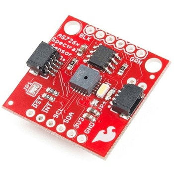
SparkFun Spectral Sensor Breakout - AS7263 NIR Qwiic
SPARKFUN¥9,998税込¥10,9981個33日以内出荷Description。The SparkFun AS7263 Near Infrared(NIR)Spectral Sensor Breakout brings spectroscopy to the palm of your hand, making it easier than ever to measure and characterize how different materials absorb and reflect different wavelengths of light. The AS7263 Breakout is unique in its ability to communicate by both an I2C interface and serial interface using AT commands. Hookup is easy, thanks to the Qwiic connectors attached to the board --- simply plug one end of the Qwiic cable into the breakout and the other into one of the Qwiic shields, then stack the board on a development board. You'll be ready to upload a sketch to start taking spectroscopy measurements in no time.。The AS7263 spectrometer detects wavelengths in the visible range at 610, 680, 730, 760, 810 and 860nm of light, each with 20nm of full-width half-max detection. The board also has multiple ways for you to illuminate objects that you will try to measure for a more accurate spectroscopy reading. There is an onboard LED that has been picked out specifically for this task, as well as two pins to solder your own LED into.。Note:The I2C address of the AS7263 is 0x49 and is hardware defined. A multiplexer/Mux is required to communicate to multiple AS7263 sensors on a single bus. If you need to use more than one AS7263 sensor consider using the Qwiic Mux Breakout.。The SparkFun Qwiic Connect System is an ecosystem of I2C sensors, actuators, shields and cables that make prototyping faster and less prone to error. All Qwiic-enabled boards use a common 1mm pitch, 4-pin JST connector. This reduces the amount of required PCB space, and polarized connections mean you can't hook it up wrong.。Get Started with the SparkFun AS726X Spectral Sensor Breakout Guide。Features。6 near-IR channels:610nm, 680nm, 730nm, 760nm, 810nm and 860nm, each with 20nm FWHM。NIR filter set realized by silicon interference filters。16-bit ADC with digital access。Programmable LED drivers。2.7V to 3.6V with I2C interface。2x Qwiic connectorsアズワン品番67-0426-70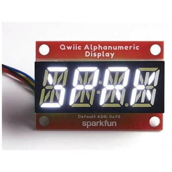
SparkFun Qwiic Alphanumeric Display - White
SPARKFUN¥2,998税込¥3,2981個33日以内出荷Description。We are quite familiar with seven-segment displays. We see them on our alarm clocks, ovens, and microwaves. By adding more segments to each digit you can display more than just numbers! Introducing the brand new SparkFun Qwiic Alphanumeric Display. These white fourteen-segment digits allow you display all sorts of numbers, characters, and symbols. With Qwiic, simply plug it in and go. No soldering, no figuring out which is SDA or SCL, and no voltage regulation or translation required!。The SparkFun Alphanumeric Display Arduino library makes printing strings to the display as easy as calling the print()function. With this library, you'll be able to send I2C commands to the VK16K33 LED driver chip to light up segments(including the decimal point or colon)and even scroll your string across the display. You can download the library through the Arduino library manager by searching 'SparkFun Alphanumeric Display' or you can get the GitHub repo as a .zip file and install the library from there.。The VK16K33 also supports I2C address configuration. Simply close a combination of the address jumpers on the back and you can communicate with up to four displays on the same bus. Our slim board design also features detachable stand off holes, vertical Qwiic connectors, and internal mounting holes.。The SparkFun Qwiic Connect System is an ecosystem of I2C sensors, actuators, shields and cables that make prototyping faster and less prone to error. All Qwiic-enabled boards use a common 1mm pitch, 4-pin JST connector. This reduces the amount of required PCB space, and polarized connections mean you can't hook it up wrong.。Get Started with the Qwiic Alphanumeric Display Hookup Guide。Features。White display。Operating Voltage:3.3V。Integrated RC oscillator。Maximum display segment numbers:128 patterns。13×3 matrix key scan circuit。16-step dimming circuit。I2C Addresses:0x70(0x71, 0x72, 0x73)。2x Qwiic connectors。2x Wall Mounting Pointsアズワン品番67-0421-87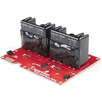
SparkFun Qwiic Dual Solid State Relay
SPARKFUN¥39,980税込¥43,9781個33日以内出荷Description。The SparkFun Qwiic Dual Solid State Relay is a power delivery board that allows users to switch two AC loads from a low power microcontroller using the SparkFun Qwiic connect system. The board features two 25A/250VAC solid state relays that utilize the Zero Cross Trigger method so you can toggle two loads on a 60Hz AC carrier signal on and off up to 120 times per second!。An ATTiny84 acts as the "brain" of the SparkFun Qwiic Dual Solid Relay to accept I2C commands to toggle the two relays as well as a few other special commands. The I2C address of the ATtiny84A is software configurable so, if you have a seriously big power project in mind, you could daisy chain over 100 Qwiic Dual Solid State Relays.。Messing with such high voltage is dangerous! We've included many safety precautions onto the PCB including ground isolation between the relay and other circuitry and a milled out area isolating each side of AC. However, with all the safety precautions included with the SparkFun Qwiic Dual Solid State Relay, this is still a power accessory for users who are experienced around, and knowledgeable about high AC voltage. If you're not comfortable with handling AC voltage in this way, you may want to check out the IoT Power Relay instead.。Note:The relays are rated for a max of 25A with forced air cooling. If you do not have forced air cooling, 10A max through the relays is recommended.。The SparkFun Qwiic connect system is an ecosystem of I2C sensors, actuators, shields and cables that make prototyping faster and less prone to error. All Qwiic-enabled boards use a common 1mm pitch, 4-pin JST connector. This reduces the amount of required PCB space, and polarized connections mean you can't hook it up wrong.。Get Started with the SparkFun Qwiic Dual Solid State Relay Guide。Features。Operating Voltage:2.5-3.6V(3.3V recommended)。I2C Address:0x0A(Default)0x0B(Alternate via jumper select)。Load Voltage Range:12-280VAC。Max Current(Through Relay):25A(240VAC with forced air cooling)。Zero Cross Trigger。Normally Open Circuit Only。2x Qwiic Connectorアズワン品番67-0421-58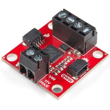
SparkFun Qwiic Motor Driver
SPARKFUN¥6,698税込¥7,3681個33日以内出荷。Description。The SparkFun Qwiic Motor Driver takes all the great features of the Serial Controlled Motor Driver(SCMD)and miniaturizes them, adding Qwiic ports for plug and play functionality. Boasting the same 4245 PSOC and 2-channel motor ports as the SCMD, the SparkFun Qwiic Motor Driver is designed to communicate over I2C to make setting up your next robotic project as fast and easy as possible! Utilizing our handy Qwiic system and screw terminals for motor and power hook-up, no soldering is required to connect it to the rest of your system.。With 1.2A steady state drive per channel(1.5A peak)and 127 levels of DC drive strength, this little Qwiic board is perfect for your small DC motor driver needs. Since the Qwiic Motor Driver is a 3.3V logic device, you'll need to use a logic level converter to interface to 5V.。The I2C address of the Qwiic Motor Driver is 0x5D and is jumper selectable to 0x58, 0x59, 0x5A, 0x5B, ... 0x63.。The SparkFun Qwiic Connect System is an ecosystem of I2C sensors, actuators, shields and cables that make prototyping faster and less prone to error. All Qwiic-enabled boards use a common 1mm pitch, 4-pin JST connector. This reduces the amount of required PCB space, and polarized connections mean you can't hook it up wrong.。Need a custom board? This component can be found in SparkFun's A La Carte board builder. You can have a custom design fabricated with this component - and your choice of hundreds of other sensors, actuators and wireless devices - delivered to you in just a few weeks.。Get Started With the Qwiic Motor Driver Hookup Guide。Features。1.5 A peak drive per channel, 1.2 A steady state。Operates from 3 to 11 Volts with 12V absolute max。3.3V default VCC and logic。127 levels of DC drive strength.。Controllable by I2C or TTL UART signals。Direction inversion on a per motor basis。Global Drive enable。Exposed small heat sink shape。Several I2C addresses, default UART bauds available。Adjustable I2C Address:0x5D Default。2x Qwiic Connectors。。Documents。Schematic。Eagle Files。Board Dimensions。Hookup Guide。Arduino Library。Python Module。Github Hardware Repoアズワン品番67-0426-33