カテゴリ
- 制御機器(20)
- 測定用品(10)
- 学童・教育用品(4)
絞り込み
ブランド
- 新日本無線(6)
- MICROCHIP(3)
- SIEMENS(3)
- DIGILENT(3)
- SPARKFUN(3)
- Pico Technology(3)
- ANALOG DEVICES(2)
- アズワン(1)
- テクシオ・テクノロジー(GW INSTEK)(1)
- エレキット(1)
- CONTEC(コンテック)(1)
- RIGOL(リゴル)(1)
- Tektronix(テクトロニクス)(1)
- RS PRO(1)
- JRC(日本無線)(1)
- Murata Power Solutions(1)
- マルツエレック(1)
- OWON(オウオン)(1)
エコロジープロダクト



「analog devices」の検索結果
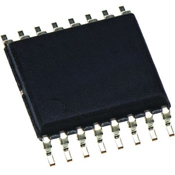
Analog Devices 周波数シンセサイザIC 10ピン
ANALOG DEVICES¥1,898税込¥2,0881袋(2個)翌々日出荷仕様カテゴリー = ダイレクトシンセサイザコンバージョンレート = 16Msps分解能 = 10ビット最大出力周波数 = 5MHz実装タイプ = 表面実装パッケージタイプ = LFCSP WDピン数 = 10寸法 = 3.1 x 3.1 x 0.8mm高さ = 0.8mm長さ = 3.1mm動作供給電圧 Max = 5.5 V動作温度 Max = +125 ℃動作供給電圧 Min = 2.3 V動作温度 Min = -40 ℃幅 = 3.1mmダイレクトデジタルシンセサイザ(DDS) / 変調器、Analog Devices. ダイレクトデジタルシンセサイザ(DDS)は、固定周波数の基準クロックから任意のアナログ波形を発生するために使用する多機能デバイスです。 これらの製品は、信号生成、通信システム、関数発生器、サウンドシンセサイザなどの多数の用途に使用できます。RoHS指令(10物質対応)対応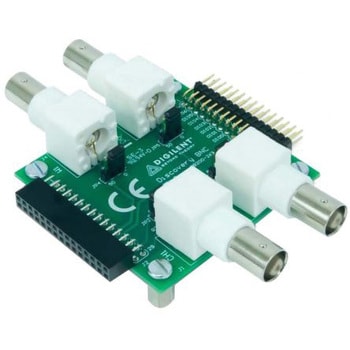
Digilent オシロスコープ用アダプタ
DIGILENT¥3,698税込¥4,0681個当日出荷仕様●アダプタタイプ = BNCアダプタボード●併用可能製品 = Analog Discovery 2●モデル番号(P) = 410-263Discovery 2キット: プロジェクトボックス、USBケーブル、15フライワイヤ信号ケーブルアセンブリ x 2、6ピンオスヘッダ5個パック、フェライトケーブルスナップオン●Discovery 2 USB PC多機能装置●Analogue Discovery 2 は、USBオシロスコープ / 多機能装置です。あらゆる種類の混合信号の測定、生成、記録、制御を行えます。●オプションの Discovery BNCアダプタボード は、標準BNCプローブを接続できるようにします。●Discovery 2は、工学系の学生、趣味人、電子工作愛好家を対象にしています。●チュートリアルその他の情報は、こちらからダウンロードできます。●2チャンネルPC USB 14ビット100 Mspsデジタルオシロスコープ 2チャンネル14ビット100 Msps任意波形発生器 ステレオオーディオヘッドホン / スピーカーアンプ 16チャンネル100 Mspsデジタルロジックアナライザ 16チャンネル100 Mspsパターン発生器 16チャンネル仮想デジタルI/O、ボタン、スイッチ、LEDを含む 複数の装置をリンクするためのI/Oデジタルトリガ信号 x 2 シングルチャンネルAC / DC電圧計 ネットワークアナライザ: 1 Hz → 10 MHz、ボード、ナイキスト、ニコルズ線図 スペクトラムアナライザ: 電力スペクトラム及びスペクトラム測定(ノイズフロア、SFDR、SNR、THDなど) SPI、I2C、UART、及びパラレルポート用デジタルバスアナライザ プログラマブル電源 x 2 (0 → +5 V、0 → -5 V) WaveForms 2015ソフトウェア(Mac、Linux、Windows対応)●RS製品コード. 134-6480/134-6480/410-321 ●Analogue Discovery 2●装置キット 134-6460/134-6460/410-263 ●Analogue Discovery BNCアダプタボードRoHS指令(10物質対応)対応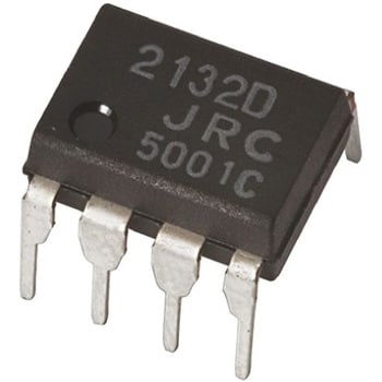
New Japan Radio オペアンプ, 8-Pin PDIP
新日本無線¥919税込¥1,0111袋(5個)当日出荷仕様実装タイプ = スルーホールパッケージタイプ = PDIP電源タイプ = デュアル1チップ当たりのチャンネル数 = 2ピン数 = 8標準ゲインバンド幅積 = 15MHz標準デュアル供給電圧 = ±12 V, ±15 V, ±3 V, ±5 V, ±9 V標準スルーレート = 5V/μs動作温度 Min = -40 ℃寸法 = 8.8 x 6.4 x 3.4mmNew Japan Radio オペアンプ, 3 ~9 V, 8-Pin PDIP
新日本無線¥679税込¥7471個当日出荷仕様実装タイプ = スルーホールパッケージタイプ = PDIP電源タイプ = シングル1チップ当たりのチャンネル数 = 2ピン数 = 8標準シングル供給電圧 = 3 → 9 V標準ゲインバンド幅積 = 20MHz標準スルーレート = 40V/μs動作温度 Max = +85 ℃標準電圧ゲイン = 75 dB高速オペアンプ、NJRRoHS指令(10物質対応)対応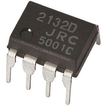
New Japan Radio オペアンプ, 8-Pin PDIP
新日本無線(1件のレビュー)¥839税込¥9231袋(5個)当日出荷仕様実装タイプ = スルーホールパッケージタイプ = PDIP電源タイプ = デュアル1チップ当たりのチャンネル数 = 2ピン数 = 8標準ゲインバンド幅積 = 3MHz標準デュアル供給電圧 = ±12 V, ±15 V, ±5 V, ±9 V標準スルーレート = 1V/μs動作温度 Max = +85 ℃幅 = 6.4mm
デジタル・オシロスコープ DS1000Zシリーズ
RIGOL(リゴル)(12件のレビュー)¥38,980~税込¥42,878~1台当日出荷から7日以内出荷高周波信号まで観測できるものが一般的であり、主に波形の分析、高速現象の観測、過渡現象の観測など、電気計測の分野で多く用いられています。New Japan Radio オペアンプ, 3~5V, 8-Pin PDIP
新日本無線¥2,798税込¥3,0781袋(5個)欠品中仕様実装タイプ = スルーホールパッケージタイプ = PDIP電源タイプ = シングル1チップ当たりのチャンネル数 = 2ピン数 = 8標準シングル供給電圧 = 3 V、5 V標準ゲインバンド幅積 = 800kHz標準スルーレート = 0.7V/μs動作温度 Min = -40 ℃幅 = 6.4mm高出力電流オペアンプ、NJRNew Japan Radio オペアンプ, 5 ~15 V, 8-Pin PDIP
新日本無線¥4,198税込¥4,6181袋(5個)翌々日出荷仕様実装タイプ = スルーホールパッケージタイプ = PDIP電源タイプ = シングル1チップ当たりのチャンネル数 = 1ピン数 = 8標準シングル供給電圧 = 5 → 15 V標準ゲインバンド幅積 = 1.5MHz標準スルーレート = 3.5V/μs動作温度 Max = +75 ℃幅 = 6.4mmLow Operating Voltage Operational Amplifiers, NJRRoHS指令(10物質対応)対応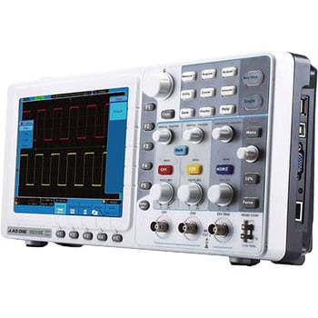
デジタルストレージオシロスコープ
アズワン(3件のレビュー)¥50,700~税込¥55,770~1個当日出荷から翌々日出荷20種類の自動測定・FFT解析が可能です。奥行き78mm、重さ1.5kgの省スペース設計です。8インチLCDディスプレイで操作性に優れたパネルとメニューです。パス・フェイル機能、波形記録・リプレイ機能付です。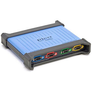
USBオシロスコープ PicoScope 4000シリーズ
Pico Technology¥219,800~税込¥241,780~1台6日以内出荷から33日以内出荷お持ちのパソコンと接続するだけでオシロスコープになるので、主張先やフィールドワークで活用できます。 ソフトウェアは各モデル共通。標準でシリアルコード機能を装備し、11種類ものフォーマットに対応。 デンゲンハUSBバスパワーから供給されるため、コンセントがないところでも使用できます。 8ch入力、絶縁入力・分解能16bit・256Mメモリ・IEPE(加速度)入力など、多彩なラインナップ。 本体は軽量コンパクトでスペースを取らずカバンの中にもスッキリ納まり、持ち運びに便利です。 演算解析や表示はパソコン能力を活用し、見やすくストレスのない使用環境を実現します。対応OSWindows7/8/10(32bitまたは64bit)OS搭載ハードウェア測定機能【波形(自動)】真の実効値、周波数、サイクルタイム、デューティーサイクル、DC平均、エッジカウント、立下がりエッジカウント、立上がりエッジカウント、立下がりレート、立上がりレート、低パルス幅、高パルス幅、立下がり時間、立上り充電時間(時間)、最小、最大、Peak to Peak、【FFT(自動)】ピーク時の周波数、ピーク時の振幅、ピーク時の平均振幅、電力合計、THD%、THD+N、THDdB、SFDR、SINAD、SNR、IMD、【統計】最小、最大、平均、標準偏差トリガー【モード】ノーマル、オート、シングル、ラビット、【種類】エッジ、ウィンドウ、パルス幅、ウィンドウパルス幅、ドロップアウト、ウィンドウドロップアウト、インターバル、ラントパルス、ロジックUSBタイプUSB3.0/USB2.0(電力はUSBポートまたは付属のACアダプタから供給)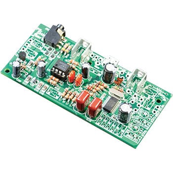
USB-DACモジュール
エレキット¥5,498税込¥6,0481個4日以内出荷パソコンのデジタルデータ音源をアナログに変換するコンバーターです。完成後はパソコンのUSB端子に接続するだけで自動的に認識するため、ドライバーのインストールなどは必要ありません。DAコンバーターにはPCM2704Cを、出力段のオペアンプにはNJM4580Dを使用し、クリアな音をお楽しみいただけます。 また、オペアンプ部はICソケットを使用していますので、お好みのオペアンプに交換し音の違いを楽むこともできます。 さらに、標準の電源供給方法であるUSBバスパワー方式を外部から電源を供給するセルフパワー方式へ変更するための切り替え端子や、外部クロックを供給する端子など、機能拡張スペースを標準で装備していますので、音質UPの工夫がやりやすくなっています。 PCL86シングルステレオパワーアンプキット(TU-8100)や6L6GCシングル真空管アンプキット(TU-8200)に組み込んで使用できるように設計されていますので、TU-8100やTU-8200のグレードアップモジュールとしてご利用いただけます。仕様(DACレゾリューション)16bit適合(USB)1.1または2.0種類工作キット対応OSWindows XP以降、Mac OS X以降周波数特性10Hz~22.5kHz(1kHz時)歪率(%)0.014(USBバスパワー時)基板寸法(mm)97×45電源供給方式USBバスパワー (外部電源を供給するセルフパワー方式へ改造可能)サンプルレート32kHz、44.1kHz、48kHz再生紙使用マーク適合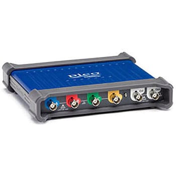
USBオシロスコープ PicoScope 3000シリーズ
Pico Technology(1件のレビュー)¥99,980~税込¥109,978~1台当日出荷から6日以内出荷お持ちのパソコンと接続するだけでオシロスコープになるので、主張先やフィールドワークで活用できます。 ソフトウェアは各モデル共通。標準でシリアルコード機能を装備し、11種類ものフォーマットに対応。 デンゲンハUSBバスパワーから供給されるため、コンセントがないところでも使用できます。 8ch入力、差動入力・分解能16bit・256Mメモリ・IEPE(加速度)入力など、多彩なラインナップ。 本体は軽量コンパクトでスペースを取らずカバンの中にもスッキリ納まり、持ち運びに便利です。 演算解析や表示はパソコン能力を活用し、見やすくストレスのない使用環境を実現します。"仕様512Mのロングメモリ、100000回/秒の波形更新レート、Windows/MAC/Linux環境で使用可能、USBバスパワーのみで動作可能、外聞電源不要対応OSWindows7/8/10(32bitまたは64bit)OS搭載ハードウェア付属プローブあり機能信号発生機能付、シリアルデコード機能(16種類標準装備)、発信機能:FG/AWG測定機能【波形(自動)】真の実効値、周波数、サイクルタイム、デューティーサイクル、DC平均、エッジカウント、立下がりエッジカウント、立上がりエッジカウント、立下がりレート、立上がりレート、低パルス幅、高パルス幅、立下がり時間、立上り充電時間(時間)、最小、最大、Peak to Peak、【FFT(自動)】ピーク時の周波数、ピーク時の振幅、ピーク時の平均振幅、電力合計、THD%、THD+N、THDdB、SFDR、SINAD、SNR、IMD、【統計】最小、最大、平均、標準偏差サンプリング1GS/sビット8bitトリガー【モード】ノーマル、オート、シングル、ラビット、【種類】エッジ、ウィンドウ、パルス幅、ウィンドウパルス幅、ドロップアウト、ウィンドウドロップアウト、インターバル、ラントパルス、ロジックUSBタイプUSB3.0/USB2.0(電力はUSBポートまたは付属のACアダプタから供給)New Japan Radio オペアンプ, 5 ~28 V, 8-Pin PDIP
新日本無線¥449税込¥4941個当日出荷仕様実装タイプ = スルーホールパッケージタイプ = PDIP電源タイプ = デュアル, シングル1チップ当たりのチャンネル数 = 2ピン数 = 8標準シングル供給電圧 = 5 → 28 V標準ゲインバンド幅積 = 1.2MHz標準デュアル供給電圧 = ±12 V, ±15 V, ±3 V, ±5 V, ±9 V標準スルーレート = 1.2V/μs動作温度 Min = -40 ℃幅 = 6.4mm汎用オペアンプ、NJRRoHS指令(10物質対応)対応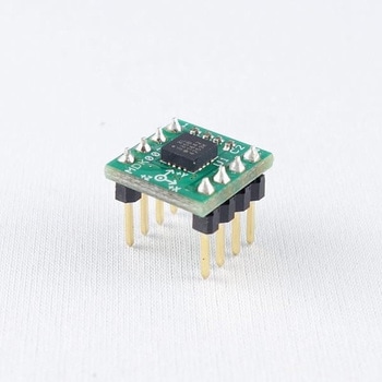
3軸加速度センサーADXL335基板
マルツエレック¥1,898税込¥2,0881個当日出荷Analog Devices社製3軸加速度センサ使用 測定レンジ ±3g センサ感度 300mV/g @Vdd=3V ArduinoやADC搭載マイコンと相性のよい3軸アナログ電圧出力(X軸、Y軸、Z軸) 2.54ピッチで、ブレッドボードでそのまま使えます。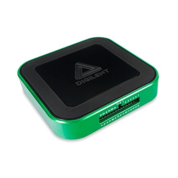
Analog Discovery 3
DIGILENT¥92,980税込¥102,2781個3日以内出荷オシロスコープや波形発生器、ロジックアナライザなど多機能な計測器 [オシロスコープ] 差動2チャンネル、分解能14ビット、最大125MS/s(1chあたり)、入力範囲±25V、帯域幅30MHz以上(BNCアダプタ使用時) 入力フィルタとロックインアンプはユーザー設定可能 FFT、スペクトログラム、アイダイアグラム、XYプロットなどの表示が可能 [任意波形発生装置] 2チャンネル、分解能14ビット、最大125MS/s(1chあたり)、出力範囲±5V、帯域幅12MHz(BNCアダプタ使用時) 標準波形、振幅変調信号、周波数変調信号、アナログ入力からの直接再生、カスタム波形、その他 [ロジックアナライザ、パターンジェネレータ] デジタルI/O:16チャンネル 3.3Vデジタル入出力(個別に設定可能)、5Vトレラント入力 SPI、I2C、UART、CAN、JTAG、ROMロジック、カスタムプロトコル、他 [プログラマブル電源] 0.5V~5V/-0.5V~-5Vの可変電源 補助電源使用時、最大800mA(1chあたり) [その他の機能] スペクトラムアナライザ、ネットワークアナライザ、インピーダンスアナライザ、プロトコルアナライザ、ボタン、スイッチ、LEDなどの仮想デジタルI/O、データロギング、電圧計、アプリ内スクリプティング LabVIEW、MATLABのサポートセット内容Analog Discovery 3、プラスチック製プロジェクトボックス ×1、USB-C to USB-C プログラミングケーブル ×1、2×15フライワイヤ信号ケーブルアセンブリ ×1、6ピンオス型ヘッダ 5個パック、30ピンフライワイヤラベル、Multisim Liveの1年間サブスクリプション、EveryMeasureの30日間トライアル(5GB、5ユーザー)チャンネル数2アナログ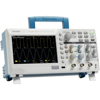
デジタルオシロスコープ
Tektronix(テクトロニクス)(2件のレビュー)¥83,980~税込¥92,378~1台ほか6日以内出荷から21日以内出荷7型WVGAカラー・ディスプレイ(水平軸メモリ数:15、表示可能な信号が50%増加) 32種類の自動測定 時間領域と周波数領域を同時に表示するデュアル・ウィンドウFFT トリガ周波数カウンタ パン/ズーム機能 多言語ユーザ・インタフェース:10言語に対応したユーザ・インタフェース/前面パネル・オーバーレイ 設置面積が小さな、小型・軽量 ファンレス設計により低ノイズを実現質量(kg)機器単体:1.979、アクセサリを含む:2.2電源100~240VAC RMS ±10%寸法(高さH×幅W×奥行D)(mm)154.95×325.12×106.68最大消費電力(W)30高度(m)動作時:最高3000、非動作時:最高12000電源周波数(Hz)45~65(100~240V)、360~440(100~132V)安全性製品の安全に関する低電圧指令2014/35/EUに適合使用環境温度(℃)動作時:0~+50、非動作時:-30~+71EMC規格EC Council Directive 2014/30/EU・UL61010-1、UL61010-2-030、CAN/CSA-C22.2 No. 61010.1、CAN/CSA-C22.2 No. 61010-2:030; EN61010-1、EN61010-2-030(電磁適合性)使用環境湿度(%)動作時:+30℃までは相対湿度(RH)5~90 / +30℃超、+50℃以下で5~60の相対湿度(RH)、結露のないこと・非動作時:+30℃までは相対湿度(RH)5~90 / +30℃超、+60℃以下で5~60の相対湿度(RH)、結露のないことサンプルレート1GS/sレコード長20kポイント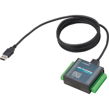
高精度アナログ入力ターミナル USB対応
CONTEC(コンテック)¥68,980税込¥75,8781個当日出荷入力点数4点分解能16-bit(ADC)、16-bit(DAC)サンプリング10μsec、ch(Max.)(レート)使用コネクタスクリュー端子台 14-pin×2アズワン品番64-8863-48入力レンジアナログ±10V出力レンジアナログ±10V応答速度(入力)200nsec(max.)バス仕様USB2.0動作電圧(V)(入力)DC3.3-LVTTL回路(入力)非絶縁LVTTLレベル入力(正論理)入力チャネル数8ch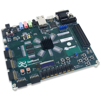
ZedBoard Zynq-7000 Development Board
DIGILENT¥159,800税込¥175,7801個5日以内出荷。※ACアダプターは同梱されておりません。Description。The ZedBoard is a low-cost development board for the Xilinx Zynq-7000 all programmable SoC(APSoC).Take advantage of the Zynq-7000 APSoCs tightly coupled ARMprocessing system and 7-Series programmable logic to create unique and powerful designs with the ZedBoard. This board contains everything necessary to create a Linux, Android, Windows, or other OS/RTOS based design. Additionally, several expansion connectors expose the processing system and programmable logic I/Os for easy user access.Target applications include video processing, reconfigurable computing, motor control, software acceleration, Linux/Android/RTOS development, exploring RISC processors(ARM), and general Zynq-7000 AP SoC prototyping.The ZedBoard is supported by Xilinx's Vivado Design Suite, including the free WebPACK version.Guides and demos are available to help users get started quickly with the ZedBoard. These can be found through the Support Materials tab. Additional resources can be found through www.zedboard.org, a community website where users can collaborate with other engineers also working on Zynq designs.。Features。XilinxZynq-7000 AP SoC XC7Z020-CLG484。Dual-core ARMCortex-A9 processor。512 MB DDR3。256 MB Quad-SPI Flash。On-board USB-JTAG Programming。10/100/1000 Ethernet。USB OTG 2.0 and USB-UART。Analog Devices ADAU1761 SigmaDSP Stereo, Low Power, 96 kHz, 24-Bit Audio Codec。Analog Devices ADV7511 High Performance 225 MHz HDMI Transmitter(1080p HDMI, 8-bit VGA, 128x32 OLED)。PS & PL I/O expansion(FMC, Pmod, XADC)。What's Included。ZedBoard APSoC development board。Custom Digilent cardboard box with protective foam。4 GB SD Card。USB A to micro-B cable。USB Adapter:Male Micro-B to Female Standard-Aアズワン品番67-0355-34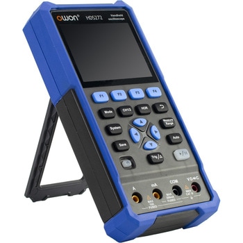
ハンドヘルド・オシロスコープ HDS200シリーズ (25MHz~200MHz、250M~1Gサンプル/秒、1/2CH)
OWON(オウオン)(6件のレビュー)¥19,980~税込¥21,978~1個ほか当日出荷から6日以内出荷【3in1多機能設計】ハンディサイズの筐体にオシロスコープ・マルチメーター・波形発生器(波形発生器はSモデルのみ)を集約。これ1台で開発・実験・現場作業まで幅広く対応。 【幅広い帯域と高速サンプリング】25MHz~200MHz帯域(モデルによる)と最大1GSa/sサンプリングで、高速信号や突発波形を高精度に解析。 【高機能マルチメーター内蔵】20,000~24,000カウント分解能で電圧・電流・抵抗・容量・温度・導通チェックなど多彩な測定に対応。研究・教育・現場作業を効率化。 【携帯性とPC連携】コンパクト設計&約4時間連続駆動。USB Type-C充電・通信対応で、SCPIコマンドによるリモート制御やPCデータ連携も可能。用途波形の分析、高速現象の観測、過渡現象の観測、電気計測、点検用、バグ解析ディスプレイ3.5インチLCDメモリ長さ8K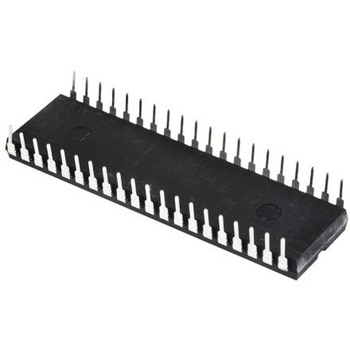
Microchip マイコン, 40-Pin PDIP PIC16F871-I/P
MICROCHIP¥9,198税込¥10,1181セット(10個)7日以内出荷PIC16F870 871 8ビットマイクロコントローラ. The PIC16F range of microcontrollers from Microchip are 8-bit MCUs that incorporate Microchip ’s PICR architecture into variety of pin and package options, from space efficient 14-pin devices to feature-rich 64-pin devices. Devices with Baseline, Mid-Range or Enhanced Mid-Range architecture are available with numerous different peripheral combinations, giving designers flexibility and choice for their applications. The PIC16F870/871 family of microcontrollers is based upon Microchip ’s Mid-Range core with an level deep hardware stack and 35 instructions. These MCUs provide up to MIPS, 3.5 Kbytes program memory, 128 bytes RAM and EEPROM of 64 bytes. マイクロコントローラの機能. 20 MHz Max. CPU Speed 35 Instructions Level Hardware Stack 22 I/O Pins PIC16F870 Model 33 I/O Pins PIC16F871 Model Power-On Reset (POR) Brown-Out Reset (BOR) Power-Up Timer (PWRT) Oscillator Start-Up Timer (OST) Watchdog Timer (WDT) In-Circuit Serial Programming (ICSP) In-Circuit Debug (ICD). 周辺機器. 10-bit Analogue-to-Digital Converter (ADC) PIC16F870 Channels, PIC16F871 Channels Capture, Compare, PWM (CCP) Module Two 8-bit Timers One 16-bit Timer Universal Synchronous Asynchronous Receiver Transmitter (USART) Parallel Slave Port (PSP) PIC16F871 Model Only仕様ファミリー名 = PIC16Fパッケージタイプ = PDIP実装タイプ = スルーホールピン数 = 40デバイスコア = PICデータバス幅 = 8bitプログラムメモリサイズ = 2 K x 14ワード、64 x 8ワード最大周波数 = 20MHzRAMサイズ = 128 BUSBチャンネル = 0PWMユニット数 = 1 x 10 bitSPIチャンネル数 = 0USARTチャネルの数 = 1寸法 = 52.45 x 14.22 x 4.06mmRoHS指令(10物質対応)対応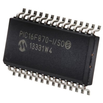
Microchip マイコン, 28-Pin SOIC PIC16F870-I/SO
MICROCHIP¥759税込¥8351個7日以内出荷PIC16F870 871 8ビットマイクロコントローラ. The PIC16F range of microcontrollers from Microchip are 8-bit MCUs that incorporate Microchip ’s PICR architecture into variety of pin and package options, from space efficient 14-pin devices to feature-rich 64-pin devices. Devices with Baseline, Mid-Range or Enhanced Mid-Range architecture are available with numerous different peripheral combinations, giving designers flexibility and choice for their applications. The PIC16F870/871 family of microcontrollers is based upon Microchip ’s Mid-Range core with an level deep hardware stack and 35 instructions. These MCUs provide up to MIPS, 3.5 Kbytes program memory, 128 bytes RAM and EEPROM of 64 bytes. マイクロコントローラの機能. 20 MHz Max. CPU Speed 35 Instructions Level Hardware Stack 22 I/O Pins PIC16F870 Model 33 I/O Pins PIC16F871 Model Power-On Reset (POR) Brown-Out Reset (BOR) Power-Up Timer (PWRT) Oscillator Start-Up Timer (OST) Watchdog Timer (WDT) In-Circuit Serial Programming (ICSP) In-Circuit Debug (ICD). 周辺機器. 10-bit Analogue-to-Digital Converter (ADC) PIC16F870 Channels, PIC16F871 Channels Capture, Compare, PWM (CCP) Module Two 8-bit Timers One 16-bit Timer Universal Synchronous Asynchronous Receiver Transmitter (USART) Parallel Slave Port (PSP) PIC16F871 Model Only仕様ファミリー名 = PIC16Fパッケージタイプ = SOIC実装タイプ = 表面実装ピン数 = 28デバイスコア = PICデータバス幅 = 8bitプログラムメモリサイズ = 2 K x 14ワード、64 x 8ワード最大周波数 = 20MHzRAMサイズ = 128 BUSBチャンネル = 0PWMユニット数 = 1 x 10 bitSPIチャンネル数 = 0USARTチャネルの数 = 1ADCユニット数 = 1RoHS指令(10物質対応)対応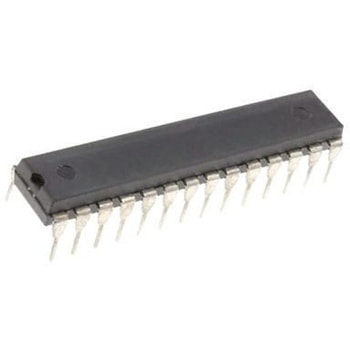
Microchip マイコン, 28-Pin SPDIP PIC16C63A-04/SP
MICROCHIP¥15,980税込¥17,5781セット(15個)7日以内出荷PIC16C63A/65B/73B/74B 8-Bit Microcontrollers. The PIC16C range of Microcontrollers from Microchip are 8-bit CMOS MCUs that incorporate Microchip ’s PICR architecture into variety of pin and package options, from space efficient 14-pin devices to feature-rich 64-pin devices. Now supplanted by Flash based variants these devices are still popular in legacy designs. For new applications PIC16F variants should be considered. The PIC16C63A/65B/73B/74B family of microcontrollers is based upon Microchip ’s mid-range architecture with an level hardware stack and 35 14-bit instructions. These MCUs provide up to MIPS, Kbytes program memory with data memory of 192 bytes RAM. On board is RC oscillator with ±1% accuracy. Features. 35 Instructions Level Hardware Stack 22 I/O Pins PIC16C63A/73B 33 I/O Pins PIC16C65B/74B Capture, Compare, PWM (CCP) Module Channel 8-bit Analogue-to-Digital Converter (ADC) PIC16C73B only Channel 8-bit Analogue-to-Digital Converter (ADC) PIC16C74B only Two 8-bit Timers One 16-bit Timer Synchronous Serial Port (SSP) with SPI and I2C Universal Synchronous Asynchronous Receiver Transmitter (USART/SCI) Parallel Slave Port PIC16C65B/74B only Watchdog Timer (WDT) Power-on Reset (POR) Power-up Timer (PWRT) Oscillator Start-up Timer (OST) Brown-out Reset (BOR) In-Circuit Serial Programming (ICSP)仕様ファミリー名 = PIC16Cパッケージタイプ = SPDIP実装タイプ = スルーホールピン数 = 28デバイスコア = PICデータバス幅 = 8bitプログラムメモリサイズ = 4 K x 14ワード最大周波数 = 4MHzRAMサイズ = 192 BUSBチャンネル = 0PWMユニット数 = 2SPIチャンネル数 = 1USARTチャネルの数 = 1長さ = 35.18mmRoHS指令(10物質対応)対応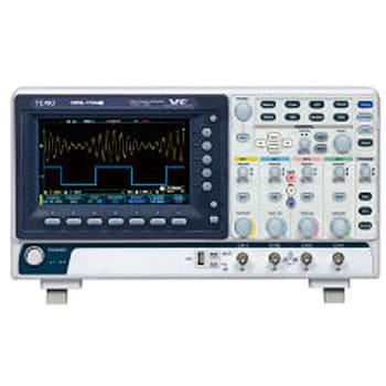
1GS/s 2ch/4chデジタルストレージオシロスコープ DCS-1000Bシリーズ
テクシオ・テクノロジー(GW INSTEK)¥78,980~税込¥86,878~1台ほか4日以内出荷から21日以内出荷大画面7インチLCD(WVGA)搭載 最高50,000回/秒の高速波形更新 最大10Mポイントのロングメモリを搭載 10種類の豊富なトリガタイプ 38項目の自動測定機能を搭載 Go-NoGo判定機能 500kポイントのFFT機能を搭載 間欠的なイベント観測に便利なセグメントメモリ機能搭載(オプション) USBメモリに波形データを自動的に保存できるデータログ機能搭載(フリーアプリケーション) USB標準装備、4CHモデルにはLANも装備付属品ユーザーマニュアルCD、電源コード、プローブ(CH数分)仕様カーソル/振幅、時間、ゲート機能あり(自動測定時)、単位:秒(s)、Hz(1/s)、位相(°)、レシオ(%)、自動測定/36項目:画面下部に最大8項目まで同時表示可能、ゲーティング機能:取り込んだ波形の任意の部分をカーソルで指定可能、電圧電流/p-p値、最大値、最小値、振幅、ハイ値、ロー値、平均、サイクル平均、RMS、サイクルRMS、エリア、サイクルエリア、ROVシュート、FOVシュート、RPREシュート、FPREシュート、パネル設定の保存/20セット質量(kg)約2.8消費電力(W)30電源電圧AC100V~240V 50~60Hz感度(垂直)1mV/div~10V/div、(トリガ)1div、(外部トリガ)DC~100MHz;約100mV寸法(幅W×高さH×奥行D)(mm)384×208×127.3分解能8ビット機能(セグメントメモリ/オプション)最大29000波形をトリガ毎に取得。メモリ長:1Kポイント>・統計演算:セグメント機能時の自動測定値の統計が可能、(波形サーチ+FFTピークサーチ/オプション)サーチ条件で波形に最大10000マークを設定・検索。最大ピークを10まで表示可能。しきい値の設定可能・ピークのイベント<周波数、振幅>を一覧表示可能。一覧をCSVでUSBへ保存できます。(デジタルフィルタ/フリーアプリケーション)ローパス/ハイパスフィルタを設定可能・CHごと、CH連動も可能。範囲:1Hz~500MHz、(データログ/フリーアプリケーション)波形データまたは画面イメージを設定間隔で設定時間までUSBメモリまたはリモートディスクLAN経由で記録します。<br>時間:2秒~2分<波形データ>、5秒~2分、時間:5分~100時間時間周波数、周期、立上り時間、立下り時間、+幅、-幅、デューティー比、+パルス、-パルス、+エッジ、-エッジインターフェース(Ethernetポート・4CHモデル)RJ-45、10/100Mbps、HP Auto-MDIX機能サポートリモートディスク機能、(盗難防止ロック)スタンダードケンジントンスタイルロックを背面パネルの盗難防止スロットに接続可能判定出力(Go-NoGo・端子)BNCメス、最大5V/10mA TTL オープンコレクタ出力表示更新レート50000波形/秒コントロール機能(パネル)Autoset/全チャンネルの垂直、水平スケールとトリガレベルを自動的に設定します。Autoset取り消し可能サンプリング(レート)最高1GS/s、使用CH数による、2CH使用時:500MS/s、3CH以上:250MS/sディスプレイ7 インチ WVGA TFT LCD入力インピーダンス1MΩ// 約16pF最大入力電圧300V rms、CAT I波形(保存)24セット極性ノーマル、反転遅延時間FRR、FRF、FFR、FFF、LRR、LRF、LFR、LFF、位相入力結合方式AC、DC、GND使用環境条件0℃~50℃、相対湿度≦ 80% at 40℃以下、相対湿度≦ 45% at 41℃~ 50℃オフセット(ポジション範囲)1mV/div:±1.25V、2mV/div~100mV/div:±2.5V、200mV/div ~10V/div:±125V言語表示日本語、英語その他使用可能RoHS指令(10物質対応)対応演算項目+・-・×・÷・FFT・FFTrms、ユーザー定義演算、ソースCH:CH1~CH4、Ref1~Ref4、(FFT)選択CHのスペクトラム振幅を表示、垂直スケール:リニアRMSまたはdBVrmsに設定可能、水平スケール:変更可能、垂直/水平ポジション:設定可能、FFTウインドウ:方形、ハミング、ハニング、ブラックマンを選択、FFT波形メモリ長:最大1Mポイント<波形メモリ:10Mポイント時>、(定義)積分・微分・log・Ln・Exp・Sqrt・Abs・Rad・Deg・Sin・Cos・Tan・Asin・Acos・Atan帯域制限70MHzモデル:20MHz BW、100MHzモデル:20MHz周波数カウンタ6桁、2Hz~定格周波数までのトリガ入力チャンネルの信号を測定平均2~256回、選択可能カーソル測定カーソル間の電圧差ΔV(電流差ΔA)、カーソル間の時間差(ΔT)、FFT時:周波数と振幅(dBまたはV)USBポートUSB 2.0 ハイスピード ホストポート×1:保存/呼出、USB 2.0 ハイスピード デバイスポート×1:PCコントロールまたは印刷DCゲイン確度±3%フルスケール:2mV/div~10V/div、±4%フルスケール:1mV/div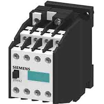
シーメンス 電磁接触器 40 → 50 V ac 8極
SIEMENS¥22,980税込¥25,2781個7日以内出荷The Siemens SIRIUS 3TH4 series is a contactor relay for switching the control signals in the control circuit。It has operating voltage of 42 V AC。The contactor relays have standard-compliant terminal designations and a reliable connection technology。The type of electrical connection for auxiliary and control current circuit is through screw terminal。Due to multiplication of outputs, simultaneous switching of up to 10 auxiliary circuits is possible。The contacts are designed with positively driven operation for safety applications as well as SUVA versions。The devices are climate-resistant and have a high contact reliability。It is approved for worldwide use e.g。IEC and UL/CSA.Protection class IP is IP20 Ambient operating temperature is -25 to +55℃仕様●コイル電圧:40 → 50 V ac●極数:8●コンタクトの定格電流:6 A●通常端子構成:4NC + 4NO●範囲:SIRIUS●コード番号:211-3711アズワン品番65-7286-08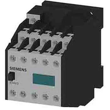
シーメンス 電磁接触器 220 → 264 V ac 10極
SIEMENS¥159,800税込¥175,7801個7日以内出荷The Siemens SIRIUS 3TH4 series is a contactor relay for switching the control signals in the control circuit。It has operating voltage of 220 to 264 V AC。The contactor relays have standard-compliant terminal designations and a reliable connection technology。The type of electrical connection for auxiliary and control current circuit is through screw terminal。Due to multiplication of outputs, simultaneous switching of up to 10 auxiliary circuits is possible。The contacts are designed with positively driven operation for safety applications as well as SUVA versions。The devices are climate-resistant and have a high contact reliability。It is approved for worldwide use e.g。IEC and UL/CSA.Protection class IP is IP20 Ambient operating temperature is -25 to +55℃仕様●コイル電圧:220 → 264 V ac●極数:10●コンタクトの定格電流:6 A●通常端子構成:4NC + 6NO●範囲:SIRIUS●コード番号:211-3714アズワン品番65-7291-56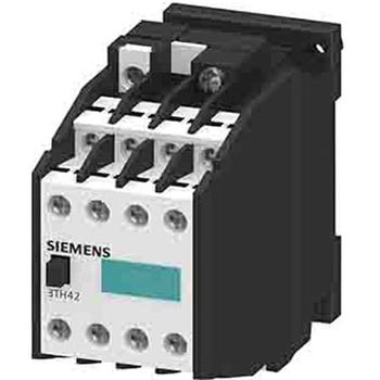
シーメンス 電磁接触器 220 → 264 V ac 8極
SIEMENS¥109,800税込¥120,7801個7日以内出荷TheSiemensSIRIUS3TH4seriesisacontactorrelayforswitchingthecontrolsignalsinthecontrolcircuit。Ithasoperatingvoltageof220VAC。Thecontactorrelayshavestandard-compliantterminaldesignationsandareliableconnectiontechnology。Thetypeofelectricalconnectionforauxiliaryandcontrolcurrentcircuitisthroughscrewterminal。Duetomultiplicationofoutputs,simultaneousswitchingofupto10auxiliarycircuitsispossible。ThecontactsaredesignedwithpositivelydrivenoperationforsafetyapplicationsaswellasSUVAversions。Thedevicesareclimate-resistantandhaveahighcontactreliability。Itisapprovedforworldwideusee.g。IECandUL/CSA.ProtectionclassIPisIP20Ambientoperatingtemperatureis-25to+55℃仕様●コイル電圧:220 → 264 V ac●極数:8●コンタクトの定格電流:6 A●通常端子構成:4NC + 4NO●範囲:SIRIUSアズワン品番65-7288-49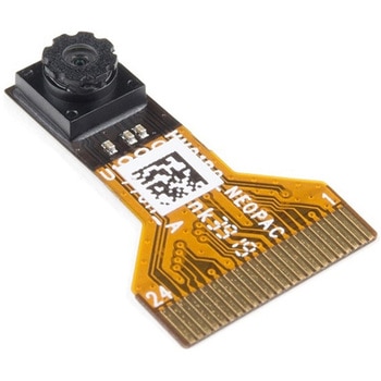
Himax CMOS Imaging Camera - HM01B0
SPARKFUN¥3,698税込¥4,0681個33日以内出荷。Description。The HM01B0 from Himax Imaging is an ultra low power CMOS Monochrome Image Sensor that enables the integration of an "Always On" camera for computer vision applications such as gestures, intelligent ambient light and proximity sensing, tracking and object identification. The sensor allows the sensor to consume very low power of <2mW at QVGA 30FPS. This low power consumption and vision applications camera comes with a ribbon cable that mates to the camera connector populated on the following products:MicroMod Machine Learning Carrier Board。Artemis Development Kit。Edge Development Board - Apollo3 Blue。The HM01B0 contains 320×320 pixel resolution and supports a 320×240 window mode which can be readout at a maximum frame rate of 60FPS, and a 2×2 monochrome binning mode with a maximum frame rate of 120FPS. The video data is transferred over a configurable 1bit, 4bit or 8bit interface with support for frame and line synchronization. The sensor integrates black level calibration circuit, automatic exposure and gain control loop, self-oscillator and motion detection circuit with interrupt output to reduce host computation and commands to the sensor to optimize the system power consumption.。Features。Image Sensor。Ultra Low Power Image Sensor(ULPIS)designed for Always On vision devices and applications。High sensitivity 3.6μ BrightSenseTM pixel technology。320×320 active pixel resolution with support for QVGA window, vertical flip and horizontal mirror readout。Programmable black level calibration target, frame size, frame rate, exposure, analog gain(up to 8x)and digital gain(up to 4x)。Automatic exposure and gain control loop with support for 50 / 60Hz flicker avoidance。Flexible 1bit, 4bit and 8bit video data interface with video frame and line sync。Motion Detection circuit with programmable ROI and detection threshold with digital output to serve as an interrupt。On-chip self oscillator。I2C 2-wire serial interface for register access。High CRA for low profile module design。Sensor Parameters。Active Pixel Array 320×320。Pixel Size 3.6 μm×3.6 μm。Full Image Area 1152 μm×1152 μm。Diagonal(Optical Format)1.63 mm(1/11″)。Scan Mode:Progressive。Shutter Type:Electronic Rolling Shutter。Frame Rate MAX 51 fps @ 320×320, 60 fps @ 320×240(QVGA)。CRA(maximum)30℃。Sensor Specifications。Supply Voltage:Analog - 2.8 V, Digital - 1.5V(Internal LDO:1.5V - 2.8V), I/O - 1.5 - 2.8V。Input Reference Clock:3 - 50 MHz。Serial Interface(I2C):2-wire, 400 KHz max.。Video Data Interface:1b, 4b, 8b with frame / line SYNC。Output Clock Rate MAX:50 MHz for 1bit, 12.5 MHz for 4bit, 6.25 MHz for 8bit。Est. Power Consumption(include IO with 5pF load):QVGA 60FPS(Typical)<4 mW。QVGA 30FPS(Typical)<2 mWアズワン品番67-0427-08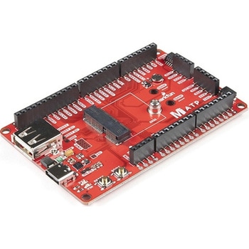
SparkFun MicroMod ATP Carrier Board
SPARKFUN¥6,298税込¥6,9281個33日以内出荷Description。Access all the pins(i.e. ATP)of the MicroMod Processor Boards with the SparkFun MicroMod ATP Carrier Board! This board breaks out the MicroMod Processor Board's pins on the M.2 connector to 0.1" spaced female headers and PTH pads on the edge of the board. This Carrier Board is great if you're interested in testing out different MicroMod Processor Boards for your application.。A modern USB-C connector makes programming easy. In addition to the pins broken out, two separate Qwiic-enabled I2C ports allow you to easily daisy chain Qwiic-enabled devices. We've exposed the SWD pins for more advanced users who prefer to use the power and speed of professional tools. A USB-A connector is provided for Processor Boards that have USB Host support. A backup battery is provided for processor boards with RTC. If you need a "lot" of GPIO with a simple-to-program, ready for market module, the ATP is the fix you need. We've even added a convenient jumper to measure the current consumption for low power testing.。MicroMod is a modular interface ecosystem that connects a microcontroller "processor board" to various "carrier board" peripherals. Utilizing the M.2 standard, the MicroMod standard is designed to easily swap out processors on the fly. Pair a specialized carrier board for the project you need with your choice of compatible processor!。Get Started with the MicroMod ATP Carrier Board Guide。Features。M.2 Connector。Operating Voltage Range。~3.3V to 6.0V(via VIN to AP7361C 3.3V Voltage Regulator)。3.3V(via 3V3)。Ports [1]。1x USB type C。1x USB type A Host。2x Qwiic Enabled I2C。1x CAN。1x I2S。2x SPI。2x UARTs。2x Dedicated Analog Pins。2x Dedicated PWM Pins。2x Dedicated Digital Pins。12x General Purpose Input Output Pins。1x SWD 2x5 header。1mAh battery backup for RTC。Buttons。Reset。Boot。LEDs。Power。3.3V。Phillips #0 M2.5x3mm screw included。[1] Note:Depending on the design of the Processor Board, not all the pins may be accessible.アズワン品番67-0423-18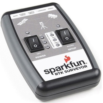
SparkFun RTK Surveyor
SPARKFUN¥129,800税込¥142,7801個33日以内出荷Description。The SparkFun RTK Surveyor is an easy to use GNSS receiver for centimeter-level positioning. Perfect for surveying, this preprogrammed device can also be used for autonomous driving, navigation, asset tracking and any other application where there is a clear view of the sky. The RTK Surveyor can also be used as a base station. With the flick of a switch, two RTK Surveyors can be used to create an RTK system capable of 14mm horizontal positional accuracy. The built-in Bluetooth(R)connection via an ESP32 WROOM enables the user to use the RTK Surveyor with their choice of GIS application on a phone or tablet. The built in battery allows field use for up to four hours and is compatible with common USB battery banks.。This device can be used in four modes:GNSS Positioning(~30cm accuracy)。GNSS Positioning with RTK(1.4cm accuracy)。GNSS Base Station。GNSS Base Station NTRIP Server。In Position mode the device receives L1/L2 signals from a user-provided antenna and the high-grade GNSS receiver provides lat/long and altitude with accuracies around 300mm.。In Positioning with RTK mode the device receives L1/L2 signals from the antenna and correction data from a base station. The correction data can be obtained from a cellular link to online correction sources or over a radio link to a 2nd RTK Surveyor setup as a base station.。In Base Station mode the device is mounted to a temporary position(like a tripod)and begins transmitting correction data over a radio or internet connection. A base is often used in conjunction with a second unit set to 'Positioning with RTK' to obtain the 14mm relative accuracy.。In Base Station NTRIP Server mode the device is mounted to a semi or permanently fixed position(like a roof)and connects over WiFi to transmit the correction data to a NTRIP caster so that any rover can access the correction data over a cellular or internet connection. This type of base is a very easy way to setup a very precise absolute correction source.。Two cables are provided with the RTK Surveyor allowing a user to plug on our easy to use Serial Telemetry Radios or their own radio link. If a local correction source is within 10km, a user can also use their phone to provide correction data over the Bluetooth(R)link(no external radio needed!).。Note:The SparkFun RTK Surveyor is just the enclosed device and does NOT include an antenna, serial telemetry radio, or associated mounting pieces. These items will need to be purchased separately from the Hookup Accessories below.。Get Started With the SparkFun RTK Surveyor Guide。Features。GNSS Receiver:ZED-F9P。Concurrent reception of GPS, GLONASS, Galileo and BeiDou。Receives both L1C/A and L2C bands。Current:68mA - 130mA(varies with constellations and tracking state)。Time to First Fix:25s(cold), 2s(hot)。Max Navigation Rate:PVT(basic location over UBX binary protocol)- 25Hz。RTK - 20Hz。Raw - 25Hz。Horizontal Position Accuracy:2.5m without RTK。0.010m with RTK。Max Altitude:50km(31 miles)。Max Velocity:500m/s(1118mph)。Bluetooth(R)Transceiver:ESP32 WROOM。Xtensa(R)dual-core 32-bit LX6 microprocessor。Up to 240MHz clock frequency。16MB of flash storage。520kB internal SRAM。Integrated 802.11 BGN WiFi transceiver。Integrated dual-mode Bluetooth(R)(classic and BLE)。Hardware accelerated encryption(AES, SHA2, ECC, RSA-4096)。2.5 μA deep sleep current。Overall Device。Internal Battery:LiPo 1000mAh with 500mA charging。Radio Port:3.3V TTL Serial(57600bps RTCM TX/RX)。Data Port:3.3V TTL Serial(115200bps NMEA)。Weight:132g(entire device including battery)。Dimensions:118mm×79mm×30mm(4.7in×3.1in×1.2in)。1x Qwiic Connector。1x microSD Socket for optional logging。Changes:This version(which replaces SPX-17369)uses a reinforced edge mount SMA connector for better resiliency when a fixed 'stub' antenna is used.アズワン品番67-0423-95