カテゴリ
- 制御機器(12)
- 学童・教育用品(7)
絞り込み
エコロジープロダクト

「lsed pw」の検索結果
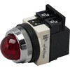
TWNシリーズ パイロットライト Φ30(丸形 LED)
IDEC(和泉電気)(12件のレビュー)¥1,298~税込¥1,428~1個当日出荷から31日以内出荷保護構造はIP65(IEC 60529)保護構造IP65使用周囲温度(℃)-25~50(ただし、氷結しないこと)使用周囲湿度45~85%RH(ただし、結露しないこと)
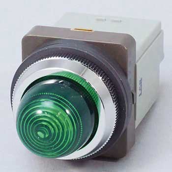
LEDパイロットライト
 (39件のレビュー)¥999~税込¥1,099~1個当日出荷光源にLEDを用いた商品になります。用途スイッチにつながれた機器の運転状態の確認に形状丸形(金属リング)保護構造IP65防油形温度上昇40K以下光源LED球絶縁抵抗(MΩ)100以上(500V)相対湿度45~85%使用周囲温度(℃)-20~55取付穴径(Φmm)30.5(+0.5~0)耐寒耐熱温度(℃)-40~70標高(m)2000以下耐衝撃(m/s2)490耐振動10~55Hz、複振幅1.5mm強度(端子部)0.8N・m 15秒間RoHS指令(10物質対応)対応耐温性40℃ 93% 96時間販売区分業務用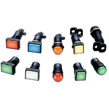
Φ16 AP6S形 小形表示灯 ドーム形
IDEC(和泉電気)¥1,298~税込¥1,428~1台当日出荷から31日以内出荷形状丸取り付け形状丸穴16mm保護構造IP65レンズ形状ドーム形光源LED本体形状一体形取付穴径(Φmm)16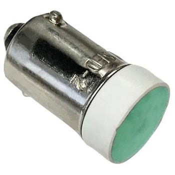
LED電球 緑 定格電圧:24V
IDEC(和泉電気)¥1,298税込¥1,4281個当日出荷BA9 ベースの LED ランプです業界標準の各種産業用制御装置で、さまざまな最新機能を備え、小型軽量で小型の 22MM YW パネル取り付けには押しボタン(照光式と非表示式)、セレクタ、パイロットライトとキースイッチには、ねじ又は新しい S3 プッシュイン Terminal 技術で終端された IP20 指保護コンタクトブロックが付属しています。BA9 ベースの LED ラ色(ライト出力)緑定格電圧(V)24口金BA9端子の種類プッシュイン取付け方法パネル取付光度(mcd)200アズワン品番65-7240-66直径(mm)10.6チップタイプマルチチップ電球の種類LEDIP等級IP20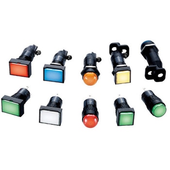
Φ16 AP6S形 小形表示灯 丸形
IDEC(和泉電気)(1件のレビュー)¥1,298~税込¥1,428~1台当日出荷から31日以内出荷形状丸取り付け形状丸穴16mm保護構造IP65レンズ形状平形光源LED本体形状一体形取付穴径(Φmm)16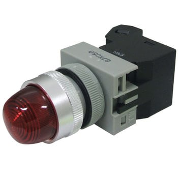
TWシリーズ パイロットライトΦ22(丸形 LED)
IDEC(和泉電気)(4件のレビュー)¥1,098~税込¥1,208~1個当日出荷から31日以内出荷保護構造はIP65(IEC 60529)形状丸保護構造IP65光源LED取付穴径(Φmm)22材質(リング)アルミニウム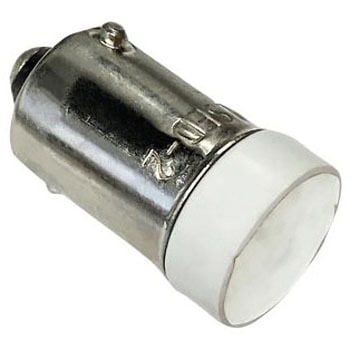
LED電球 白
IDEC(和泉電気)¥1,598税込¥1,7581個翌々日出荷から7日以内出荷BA9 ベースの LED ランプです。業界標準の各種産業用制御装置で、さまざまな最新機能を備え、小型軽量で小型の 22MM YW パネル取り付けには押しボタン(照光式と非表示式)、セレクタ、パイロットライトとキースイッチには、ねじ又は新しい S3 プッシュイン Terminal 技術で終端された指保護コンタクトブロックが付属しています。BA9 ベース LED ランプは、Idec 照光式押ボタン、回転式 / HW シリーズスイッチアセンブリで使用します。口金BA9光度(mcd)200直径(mm)10.6チップタイプマルチチップ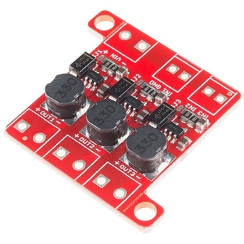
PicoBuck LED Driver
SPARKFUN¥5,298税込¥5,8281個33日以内出荷Description。The PicoBuck LED Driver is an economical and easy to use driver that will allow you to control and blend three different LEDs on three different channels. By default, each channel is driven at 330mA; that current can be reduced by either presenting an analog voltage or a PWM signal to the board. Version 12 of the board adds a solderable jumper that can be closed to increase the maximum current to 660mA. The new voltage regulator also increased the voltage rating on the various components on the board, allowing it to be used up to the full 36V rating of the AL8805 part.。Three signal inputs are provided for dimming control. You can use the PWM signal from an Arduino or your favorite microcontroller to dim each channel individually, or you can tie them all to the same PWM for simultaneous dimming. Dimming can be done by an analog voltage(20%-100% of max current by varying voltage from .5V-2.5V)or by PWM(so long as PWM minimum voltage is less than .4V and maximum voltage is more than 2.4V)for a full 0-100% range. A small jumper is provided for each channel to allow you to increase the drive strength from 330mA to 660mA. Two mounting holes for 4-40 or M3 screws are provided on either side of the board. They are perforated so they can be easily snapped off with a pair of pliers, if a smaller footprint is desired.。Note:。If you're going to use screw terminals, this board uses two different sizes. Check the related products for both sizes you'll need.。Note:。The PicoBuck LED Driver was made in collaboration with Ethan Zonca. A portion of each sale is given back to him.アズワン品番67-0420-83
LEDドライバ
SPARKFUN¥2,498税込¥2,7481個33日以内出荷Description。This is the FemtoBuck, a small-size single-output constant current LED driver. Each FemtoBuck has the capability to dim a single high-power channel of LEDs from 0-350mA at up to 36V while the dimming control can be either accessed via PWM or analog signal from 0-2.5V. This board is based off of the PicoBuck LED Driver, developed in collaboration with Ethan Zonca, except instead of blending three different LEDs on three different channels the FemtoBuck controls just one.。For the FemtoBuck, we've increased the voltage ratings on the parts to allow the input voltage to cover the full 36V range of the AL8805 driver. Since the FemtoBuck is a constant current driver, the current drawn from the supply will drop as supply voltage rises. In general, efficiency of the FemtoBuck is around 95%, depending on the input voltage. On board each FemtoBuck you will find two inputs for both power input and dimming control pins and an area to install a 3.5mm screw terminal. Finally at either side of the board you will find small indents or "ears" which will allow you to use a zip tie to secure the wires to the board after soldering them down. This version of the FemtoBuck is equipped with a small solder jumper that can be closed with a glob of solder to double the output current from 330mA to 660mA.アズワン品番67-0477-97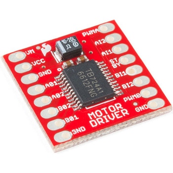
モータードライバ
SPARKFUN¥4,798税込¥5,2781個33日以内出荷Description。The TB6612FNG Motor Driver can control up to two DC motors at a constant current of 1.2A(3.2A peak). Two input signals(IN1 and IN2)can be used to control the motor in one of four function modes:CW, CCW, short-brake and stop. The two motor outputs(A and B)can be separately controlled, and the speed of each motor is controlled via a PWM input signal with a frequency up to 100kHz. The STBY pin should be pulled high to take the motor out of standby mode.。Logic supply voltage(VCC)can be in the range of 2.7--5.5VDC, while the motor supply(VM)is limited to a maximum voltage of 15VDC. The output current is rated up to 1.2A per channel(or up to 3.2A for a short, single pulse).。This little board comes with all components installed as shown. Decoupling capacitors are included on both supply lines. All pins of the TB6612FNG are broken out to two 0.1" pitch headers; the pins are arranged such that input pins are on one side and output pins are on the other.。Note:。If you are looking for the SparkFun Motor Driver with headers, it can be found here or in the。Similar Products。below.。Get Started With the Motor Driver Hookup Guide。Features。Power supply voltage:VM = 15V max, VCC = 2.7--5.5V。Output current:Iout = 1.2A(average)/ 3.2A(peak)。Standby control to save power。CW/CCW/short-brake/stop motor control modes。Built-in thermal shutdown circuit and low-voltage detecting circuit。All pins of the TB6612FNG broken out to 0.1" spaced pins。Filtering capacitors on both supply linesアズワン品番67-0395-99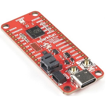
SparkFun Thing Plus - RP2040
SPARKFUN¥6,698税込¥7,3681個33日以内出荷Description。The SparkFun Thing Plus - RP2040 is a low-cost, high performance board with flexible digital interfaces featuring the Raspberry Pi Foundation's RP2040 microcontroller. Besides the Thing Plus or。Feather。footprint(with 18 GPIO pins), the board also includes an SD card slot, 16MB(128Mbit)flash memory, a JST single cell battery connector(with a charging circuit and fuel gauge sensor), an addressable WS2812 RGB LED, JTAG PTH pins, four(4-40 screw)mounting holes, and our signature Qwiic connector.。The RP2040 contains two ARM Cortex-M0+ processors(up to 133MHz)and features:264kB of embedded SRAM in six banks。6 dedicated IO for SPI Flash(supporting XIP)。30 multifunction GPIO:Dedicated hardware for commonly used peripherals。Programmable IO for extended peripheral support。Four 12-bit ADC channels with internal temperature sensor(up to 0.5 MSa/s)。USB 1.1 Host/Device functionality。The RP2040 is supported with both C/C++ and MicroPython cross-platform development environments, including easy access to runtime debugging. It has UF2 boot and floating-point routines baked into the chip. While the chip has a large amount of internal RAM, the board includes an additional 16MB of external QSPI flash memory to store program code.。The SparkFun Qwiic Connect System is an ecosystem of I2C sensors, actuators, shields and cables that make prototyping faster and less prone to error. All Qwiic-enabled boards use a common 1mm pitch, 4-pin JST connector. This reduces the amount of required PCB space, and polarized connections mean you can't hook it up wrong.。Get Started With the Thing Plus RP2040 Hookup Guide。Features。SparkFun Thing Plus - RP2040 Features。Raspberry Pi Foundation's RP2040 microcontroller。16MB QSPI Flash Memory。JTAG PTH Pins。Thing Plus(or Feather)Form-Factor:18[1]x Multifunctional GPIO Pins[2]。Four available 12-bit ADC channels with internal temperature sensor(500kSa/s)。Up to eight 2-channel PWM。Up to two UARTs。Up to two I2C buses。Up to two SPI buses。USB-C Connector:USB 1.1 Host/Device functionality。2-pin JST Connector for a LiPo Battery。(not included)。500mA charging circuit。Qwiic Connector。Buttons:Boot。Reset。LEDs:PWR。- Red 3.3V power indicator。CHG。- Yellow battery charging indicator。25。- Blue status/test LED(。GPIO 25。)。WS2812。- Addressable RGB LED(。GPIO 08。)。Four Mounting Holes:4-40 screw compatible。Dimensions:2.3"×0.9"。RP2040 General Features。Dual Cortex M0+ processors, up to 133 MHz。264 kB of embedded SRAM in 6 banks。6 dedicated IO for QSPI flash, supporting execute in place(XIP)。30 programmable IO for extended peripheral support。SWD interface。Timer with 4 alarms。Real time counter(RTC)。USB 1.1 Host/Device functionality。Supported programming languages。MicroPython。C/C++。1.。Note:。GPIO 08。is not included in this count, as it passes through the WS2812 addressable RGB LED first.。GPIO 07。and。GPIO 23。are counted as a single GPIO because they are tied together.。2.。Note:The GPIO pins are programmable so you can reconfigure the pins! Check out the RP2040 datasheet for more information on the GPIO functionality.アズワン品番67-0423-56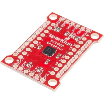
SparkFun 16 Output I/O Expander Breakout - SX1509
SPARKFUN¥2,198税込¥2,4181個33日以内出荷Description。Are you low on I/O? No problem! The SX1509 Breakout is 16-channel GPIO expander with an I2C interface that means with just two wires, your microcontroller can interface with 16 fully configurable digital input/output pins. But the SX1509 can do so much more than just simple digital pin control. It can produce PWM signals, so you can dim LEDs. It can be set to blink or even breathe pins at varying rates. This breakout is similar to multiplexer or "mux," in that it allows you to get more IO from less pins. And, with built-in keypad engine, it can interface with up to 64 buttons set up in an 8x8 matrix.。Two headers at the top and bottom of the breakout board function as the input and control headers to the board. This is where you can supply power to the SX1509, and where your I2C signals SDA and SCL will terminate. GPIO and power buses are broken out in every-which direction, and configurable jumpers cover most of the rest of the board.。Since the I/O banks can operate between 1.2V and 3.6V(5.5V tolerant)independent of both the core and each other, this device can also work as level-shifter. The SX1509 breakout makes it easy to prototype so you can add more I/O onto your Arduino or I/O limited controller. We've even spun up an Arduino Library to get you started!。Features。Enable Direct Level Shifting Between I/O Banks and Host Controller。5.5V Tolerant I/Os, Up to 15mA Output Sink on All I/Os。Integrated LED Driver with Intensity Control。On-Chip Keypad Scanning Engine Supports Up to 8x8 Matrix(64 Keys)。16 Channels of True Bi-directional Style I/O。400kHz I2C Compatible Slave Interfaceアズワン品番67-0419-88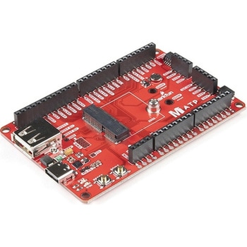
SparkFun MicroMod ATP Carrier Board
SPARKFUN¥6,298税込¥6,9281個33日以内出荷Description。Access all the pins(i.e. ATP)of the MicroMod Processor Boards with the SparkFun MicroMod ATP Carrier Board! This board breaks out the MicroMod Processor Board's pins on the M.2 connector to 0.1" spaced female headers and PTH pads on the edge of the board. This Carrier Board is great if you're interested in testing out different MicroMod Processor Boards for your application.。A modern USB-C connector makes programming easy. In addition to the pins broken out, two separate Qwiic-enabled I2C ports allow you to easily daisy chain Qwiic-enabled devices. We've exposed the SWD pins for more advanced users who prefer to use the power and speed of professional tools. A USB-A connector is provided for Processor Boards that have USB Host support. A backup battery is provided for processor boards with RTC. If you need a "lot" of GPIO with a simple-to-program, ready for market module, the ATP is the fix you need. We've even added a convenient jumper to measure the current consumption for low power testing.。MicroMod is a modular interface ecosystem that connects a microcontroller "processor board" to various "carrier board" peripherals. Utilizing the M.2 standard, the MicroMod standard is designed to easily swap out processors on the fly. Pair a specialized carrier board for the project you need with your choice of compatible processor!。Get Started with the MicroMod ATP Carrier Board Guide。Features。M.2 Connector。Operating Voltage Range。~3.3V to 6.0V(via VIN to AP7361C 3.3V Voltage Regulator)。3.3V(via 3V3)。Ports [1]。1x USB type C。1x USB type A Host。2x Qwiic Enabled I2C。1x CAN。1x I2S。2x SPI。2x UARTs。2x Dedicated Analog Pins。2x Dedicated PWM Pins。2x Dedicated Digital Pins。12x General Purpose Input Output Pins。1x SWD 2x5 header。1mAh battery backup for RTC。Buttons。Reset。Boot。LEDs。Power。3.3V。Phillips #0 M2.5x3mm screw included。[1] Note:Depending on the design of the Processor Board, not all the pins may be accessible.アズワン品番67-0423-18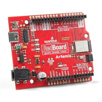
SparkFun RedBoard Artemis
SPARKFUN¥7,698税込¥8,4681個33日以内出荷。Description。Think of the RedBoard Artemis as just another Arduino... That has BLE. And one megabyte of flash. And runs at less than 1mA. Oh, and it can run TensorFlow models. Ya, that too. The RedBoard Artemis takes the incredibly powerful Artemis module from SparkFun and wraps it up in an easy to use and familiar Uno footprint. We've written an Arduino core from scratch to make programming the Artemis as familiar as。Serial.begin(9600)。. Time-to-first-blink is less than five minutes.。The RedBoard Artemis has the improved power conditioning and USB to serial that we've refined over the years on our RedBoard line of products. A modern USB-C connector makes programming easy. A Qwiic connector makes I2C easy. The RedBoard Artemis is fully compatible with SparkFun's Arduino core and can be programmed easily under the Arduino IDE. We've exposed the JTAG connector for more advanced users who prefer to use the power and speed of professional tools. We've added a digital MEMS microphone for folks wanting to experiment with always-on voice commands with TensorFlow and machine learning. We've even added a convenient jumper to measure current consumption for low power testing.。With 1MB flash and 384k RAM you'll have plenty of room for your sketches. The on-board Artemis module runs at 48MHz with a 96MHz turbo mode available and with Bluetooth to boot!。The SparkFun RedBoard Artemis is a great platform to 'kick the tires' of this amazing module. If you're interesting in testing out the full capabilities of the SparkFun Artemis module or if you're looking for more compact solution, be sure to checkout our ATP and Nano versions of the Artemis line.。Get Started With the SparkFun Artemis RedBoard Guide。Features。Arduino Uno R3 Footprint。1M Flash / 384k RAM。48MHz / 96MHz turbo available。24 GPIO - all interrupt capable。21 PWM channels。Built in BLE radio。10 ADC channels with 14-bit precision。2 UARTs。6 I2C buses。4 SPI buses。PDM Interface。I2S Interface。Qwiic Connectorアズワン品番67-0422-82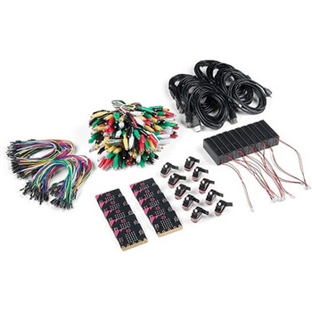
SparkFun Educator Lab Pack for micro:bit v2
SPARKFUN¥109,800税込¥120,7801個33日以内出荷Description。The micro:bit v2 Educator's Lab Pack includes 10 micro:bit v2 boards and everything you need to get you started with the new learning platform. The Lab Pack has everything you need, including micro:bits, cables, battery packs and a few parts to experiment with. This package provides an easy way to introduce your students to the micro:bit without any difficulty or parts hunting.。SparkFun packages everything educators need to get started with the micro:bit in a variety of classroom settings and learning environments. The hardware boards, cables and extra parts come pre-packaged. Examples and curriculum materials are available from SparkFun and micro:bit, as well as from other educators involved in this growing maker education movement.。Lab Packs are your classroom entry point. By combining our kits, popular boards and other educational tools with support materials(to be updated), SparkFun brings all the power of the open source community to the classroom. We've also updated the battery pack to be closer to what is in other micro:bit kits. It now requires 2xAAA batteries.。The micro:bit is a pocket-sized computer that lets you get creative with digital technology. Between the micro:bit and our shield-like bit boards you can do almost anything while coding, customizing and controlling your micro:bit from almost anywhere! You can use your micro:bit for all sorts of unique creations, from robots to musical instruments and more. At half the size of a credit card, this versatile board has vast potential!。。Features。Micro:bit 2.0:64 MHz Arm Cortex-M4 with FPU。512KB Flash。128KB RAM。5x5 Red LED Array。Two Programmable Buttons, one touch sensitive logo。MEMS microphone and LED indicator。Onboard Light, Compass, Accelerometer, Temp Sensors and Speaker。2.4 Ghz Micro:bit Radio/BLE 5.0 Smart Antenna。25-pin Edge Connector。4 dedicated GPIO, PWM, i2c, SPI, and ext. power。Three Digital/Analog Input/Output Rings。Two Power Rings --- 3V and GND。Dedcated I2C bus for peripherals。MicroUSB Connector(5V)。JST-PH Battery Connector(。Not。JST-XH)(3V)。Power/reset Button with Status LED。200 mA available for accessories。Program with C++, MakeCode, Python, Scratchアズワン品番67-0424-92