カテゴリ
- 学童・教育用品(53)
- 制御機器(9)
絞り込み
ブランド
- SPARKFUN
- モノタロウ(2)
- Kawasaki(2,544)
- TE Connectivity Japan(旧:TYCOELECTRONICS(タイコエレクトロニクス))(814)
- RS PRO(648)
- TAKEGAWA(武川)(440)
- AWJ(410)
- AMPHENOL(321)
- 長谷川工業(302)
- NSK(日本精工)(126)
- YAZAWA(ヤザワコーポレーション)(125)
- ゴールドメダル(120)
- Qlight(119)
- StarTech.com(111)
- GPR Exhaust (ジーピーアールエキゾースト)(111)
- エレコム(98)
- FCT - A MOLEX COMPANY(68)
- LEPLUS NEXT(67)
- Panasonic(パナソニック)(58)
- PANDUIT(パンドウイット)(55)
- ブランドをもっと見る
「AN AW」の検索結果
 Audio Cable to Alligator Clips - 2.5mmSPARKFUN
¥309税込¥340
1個
33日以内出荷
DescriptionThis is an Audio to Alligator Cable, an 8in. long 22 AWG wire with two alligator clips at one end and a 2.5mm mono plug at the other.
アズワン品番67-0420-69
 SparkFun Qwiic Button - Green LEDSPARKFUN
¥1,698税込¥1,868
1個
33日以内出荷
DescriptionButtons are an easy and tactile way to interface with your project, but why would you want to deal with debouncing, polling, and wiring up pull-up resistors? The Qwiic Button with built-in green LED simplifies all of those nasty worries away into an easy to use I2C device! Utilizing our Qwiic Connect System, using the button is as simple as connecting cable and loading up some pre-written code!If you need multiple buttons for your project, fear not! Each button has configurable I2C address, so you can daisy-chain multiple buttons over Qwiic and still address each one individually. We've got an example in our Arduino library that provides super-easy way to configure your Qwiic Button to whatever I2C address you desire. You can download the library through the Arduino library manager by searching 'SparkFun Qwiic Button' or you can get the GitHub repo as .zip file and install the library from there.In addition to handling blinking and debouncing, the Qwiic Button has configurable interrupts that can be configured to activate upon button press or click. We've also taken the liberty of implementing FIFO queue onboard the Qwiic Button where it keeps an internal record of when the button was pressed. This means that code on your microcontroller need not waste valuable processing time checking the status of the button but instead can run small function whenever the button is pressed or clicked! For more information on interrupts check out our guide here!The SparkFun Qwiic Connect System is an ecosystem of I2C sensors, actuators, shields and cables that make prototyping faster and less prone to error. All Qwiic-enabled boards use common 1mm pitch, 4-pin JST connector. This reduces the amount of required PCB space, and polarized connections mean you can't hook it up wrong.Get Started with the SparkFun Qwiic Button GuideFeatures12mm Green LED Button rated for 50mABuilt in LED can be configured for your desired level of blinkiness!Each button has configurable I2C addressConfigurable interrupts check out our guide here!FIFO queueDon't like the color green? Check out the SparkFun Qwiic Button Breakout and add another colored button!Red LED Tactile ButtonBlue LED Tactile ButtonGreen LED Tactile ButtonWhite LED Tactile Button
アズワン品番67-0420-14
 USB to TTL Serial Cable 5V VCCSPARKFUN
¥5,198税込¥5,718
1個
欠品中
DescriptionThis is a USB to TTL Serial Cable which allows for a simple way to connect TTL interface devices to USB. The I/O pins of this cable are configured to operate at 3.3V specifically with a Raspberry Pi with each serial pin broken apart. Thanks to its separated pins, this cable is a perfect candidate for powering, connecting, and accessing the login and debug console on an older-version Raspberry Pi.The FTDI cable is designed around an FT232, which is housed in a USB-A connector. The other side of the cable is terminated with a separated 4-pin connector with the following pinout:RX(Yellow), TX(Orange), VCC(5V)(Red), and GND(Black). A link to the FTDI drivers can be found in theDocumentssection above.Note:Please be aware that while the I/O pins in this cableoperate at 3.3V, the VCC pin is 5V. The VCC pin is NOT 3.3V like theI/O pins.
アズワン品番67-0420-67
 Jumper Wires Premium 4" M/M - 26 AWG 30 PackSPARKFUN
¥879税込¥967
1個
33日以内出荷
DescriptionThese are 101mm long 26AWG jumpers with male connectors on both ends. Use these to jumper from any female header on any board to any other female header. Combine these with our female-to-female jumpers to create a male-to-female jumper. Multiple jumpers can be installed next to one another on a 0.1" header.Comes as one pack of 30 jumpers with an assortment of colors.Features4" long
アズワン品番67-0425-33
 SparkFun MP3 Player ShieldSPARKFUN
¥11,980税込¥13,178
1個
欠品中
DescriptionThe SparkFun MP3 Player Shield is an awesome MP3 decoder with the capabilities of storing music files onto a run-of-the-mill microSD card, thus giving you the ability toadd music or sound effects to any project. With this board you can pull MP3 files from an microSD card and play them using only one shield, effectively turning any Arduino into a fully functional stand-alone MP3 player! The MP3 Shield utilizes the VS1053B MP3 audio decoder IC to decode audio files. The VS1053 is also capable of decoding Ogg Vorbis/MP3/AAC/WMA/MIDI audio and encoding IMA ADPCM and user-loadable Ogg Vorbis.The VS1053 receives its input bitstream through a serial input bus(SPI). After the stream has been decoded by the IC, the audio is sent out to both a 3.5mm stereo headphone jack, as well as a 2-pin 0.1" pitch header.This shield comes populated with all components as shown in the images and schematic; but it does not come with headers installed. We recommend the Arduino R3 Stackable Header Kit.Features3.5mm audio out jack0.1" spaced header for speaker outmicroSD card slot
アズワン品番67-0422-08
 SparkFun Servo Trigger - Continuous RotationSPARKFUN
¥4,898税込¥5,388
1個
33日以内出荷
DescriptionThe SparkFun Continuous Rotation(CR)Servo Trigger is a small robotics board that simplifies the control of hobby RC servo motors. When an external switch or logic signal changes state, the CR Servo Trigger is able to tell an attached servo motor to move from position A to position B. To use the CR Servo Trigger, you simply connect a hobby servo and a switch, then use the on-board potentiometers to adjust the start/stop positions and the transition time. You can use a hobby servo in your projects without having to do any programming!When we introduced the original Servo Trigger, we mentioned that it could be reprogrammed to be more useful with continuous rotation servo motors. But reprogramming the firmware is somewhat tedious, and users asked for a Servo Trigger preprogrammed with the continuous rotation logic. With this little board you will be provided an easy way to deploy continuous rotation servos into your projects!The heart of the CR Servo Trigger is an Atmel ATtiny84 microcontroller, running a small program that implements the servo control features designed for continuous rotation servos. On board each of these CR Servo Triggers you will find three potentiometers:"A" sets the position the servo sits in while the switch is open, "B" sets the position the servo moves to when the switch is closed, and "T" sets the time it takes to get from A to B and back.Compared with a servo motor, the CR Servo Trigger board draws very little current, roughly 5mA at 5V. Be sure to note that if you're using the CR Servo Trigger to control your motor, the absolute maximum supply voltage that should be applied is 5.5 VDC. Additionally, the SparkFun CR Servo Trigger is designed to make it easy to daisy chain boards - you can simply connect the VCC and GND pads on adjacent boards to each other.Note:This idea originally came from our friend in the Oakland area, CTP. If you see him, please give him a high-five for us.SparkFun CR Servo Trigger Hookup GuideFeaturesRecommended Voltage:5VDCMax Voltage:5.5VDCCurrent Draw:5mAControl Continuous Rotation ServosThree Control SettingsA - sets the position the servo sits in while the switch is openB - sets the position the servo moves to when the switch is closedC - sets the time it takes to get from A to B and backEasy Control with PotentiometersConfigurable Input PolarityConfigurable Response ModeCompatible with Analog ServosISP Header Pins Available for Reprogram
アズワン品番67-0429-21
 SparkFun Load Sensor CombinatorSPARKFUN
¥839税込¥923
1個
欠品中
DescriptionThe SparkFun Load Sensor Combinator is a bare PCB that combines four load sensors into a standard four-wire Wheatstone bridge configuration. If you open up an electronic bathroom scale, you'll find a large rat's nest of wires. The Load Sensor Combinator was created to combine the 12 wires found in a bathroom scale into the standard four-wire Wheatstone bridge configuration.This version of the SparkFun Load Sensor Combinator features a few changes that you specifically asked for! We updated the silk on the breakout to read "C/+/-" instead of "R/W/B" and moved the temperature sensor connector away from the standoff hole.You can either use four individual load sensors or simply purchase an off-the-shelf bathroom scale and hack the combinator into it rather than trying to design a base to properly mount four load sensors.This board works great with our Load Cell Amplifier breakout board; the five pins on the edge of the combinator line up directly to the five pins on the amplifier.If your amplifier and supporting electronics are more than a few inches away from the scale, an RJ45 footprint is provided. The four Wheatstone pins(E+/E-/S+/S-)as well as the shield pin are connected to twisted pairs within a standard cheap Ethernet cable. This allows the amplifier board to be placed many feet away from the scale itself.The combinator board also includes a footprint for the DS18B20 one-wire temperature sensor. This allows the user to gather the temperature of the scale in case there is a large variance between the scale and the amplifier. These three pins are accessed through the RJ45 connection as well, allowing remote temperature readings to be gathered over one twisted pair Ethernet cable.NOTE:The SparkFun Load Sensor Combinator will only work with 3 wire load sensors, it is not compatible with 4 wire load cells.
アズワン品番67-0419-93
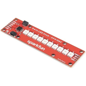 SparkFun Qwiic LED Stick - APA102CSPARKFUN
¥3,500税込¥3,850
1個
33日以内出荷
DescriptionThe SparkFun Qwiic LED Stick features ten addressable APA102 LEDs, making it easy to add full color LED control using I2C. Write to individual LEDs to display a count in binary, or write to the whole strip for cool lighting effects. You can even add more LEDs to the end if you need to. We've written an Arduino library and Python package that take care of the I2C and communication to the LEDs so all you have to do is decide what color each LED should be.The LED Stick has a default I2C address of 0x23 but can be changed with a simple command, allowing you to control up to 100 LEDs(10 Qwiic LED Sticks)on a single bus! The address can also be changed to 0x22 by closing the solder jumper on the back of the board.This board is one of our many Qwiic compatible boards! Simply plug and go. No soldering, no figuring out which is SDA or SCL, and no voltage regulation or translation required!Warning:Using a lot of LEDs can draw a lot of current. Make sure to consider the power limits of your setup. If you expect your LED chain to draw more than 600mA of current, connect your external supply directly to VLED. Closing the jumper from VLED to VCC will add a 4.7uF decoupling capacitor.The SparkFun Qwiic Connect System is an ecosystem of I2C sensors, actuators, shields and cables that make prototyping faster and less prone to error. All Qwiic-enabled boards use a common 1mm pitch, 4-pin JST connector. This reduces the amount of required PCB space, and polarized connections mean you can't hook it up wrong.Get Started with the Qwiic LED Stick GuideFeatures10x APA102C addressable LEDs driven by an ATTiny85Default I2C Address:0x23(Adjustable to 0x22 via Jumper)2x Qwiic Connectors
アズワン品番67-0421-83
 Teensy Arduino Shield AdapterSPARKFUN
¥4,798税込¥5,278
1個
33日以内出荷
DescriptionThe Teensy is an amazing and compact development platform in breadboard friendly form factor, but what if you could incorporate it into the Arduino architecture? The Teensy Arduino Shield Adapter allows you to attach your Teensy and utilize your favorite Arduino shields without the requirement of breadboard or any complicated wiring. Needless to say, the Teensy Arduino Shield Adapter is useful tool for upgrading all of your existing Arduino projects to more powerful controller!As we stated before, the Teensy Arduino Shield Adapter provides basic Arduino compatibility with your run-of-the-mill shield but there are few other fun features that we've added on, as well. These features include Real Time Clock(RTC)battery, JST battery connector, 4-12V barrel jack connector, an ICSP header, and more. Because this board is simply an adapter, there is no special programming required to start working with the adapter. You will, however, need to program the Teensy for any Arduino shield you'd like to work with.While the adapter design can fit the Teensy LC footprint, it has been designed to fully utilize the features of the Teensy 3.1. Not all of the features available on the adapter are compatible with the LC so please be sure to check the Hookup Guide in theDocumentssection below to ensure functionality for your project. Please keep in mind that this adapter may be incompatible with some 5V Arduino shields. Please check our hookup guide for more information.Note:The Teensy Arduino Shield Adapter comes as kit and will need to be soldered together.Note:Due to the requirements of shipping the batteries in this kit, orders may take longer to process and therefore do not qualify for same-day shipping. Additionally, these batteries can not be shipped via Ground or Economy methods to Alaska or Hawaii. Sorry for any inconvenience this may cause.FeaturesArduino R3 InterfaceReal Time Clock BatteryJST Battery ConnectorBarrel JackI2C JumpersICSP HeaderDAC Pin Header
アズワン品番67-0424-36
 SparkFun Pulse Oximeter and Heart Rate Sensor - MAX30101 & MAX32664 QwiicSPARKFUN
¥13,980税込¥15,378
1個
33日以内出荷
DescriptionThe SparkFun Pulse Oximeter and Heart Rate Sensor is an I2C based biometric sensor, utilizing two chips from Maxim Integrated:the MAX32664 Biometric Sensor Hub and the MAX30101 Pulse Oximetry and Heart Rate Module. While the latter does all the sensing, the former is an incredibly small and fast Cortex M4 processor that handles all of the algorithmic calculations, digital filtering, pressure/position compensation, advanced R-wave detection, and automatic gain control. We've provided a Qwiic connector to easily connect to the I2C data lines but you will also need to connect to two additional lines. This board is very small, measuring at 1in×0.5in(25.4mm×12.7mm), which means it will fit nicely on your finger without all the bulk.The MAX30101 does all the sensing by utilizing its internal LEDs to bounce light off the arteries and arterioles in your finger's subcutaneous layer and sensing how much light is absorbed with its photodetectors. This is known as photoplethysmography. This data is passed onto and analyzed by the MAX32664 which applies its algorithms to determine heart rate and blood oxygen saturation(SpO2). SpO2 results are reported as the percentage of hemoglobin that is saturated with oxygen. It also provides useful information such as the sensor's confidence in its reporting as well as a handy finger detection data point. To get the most out of the sensor we've written an Arduino Library to make it easy to adjust all the possible configurations.The SparkFun Qwiic connect system is an ecosystem of I2C sensors, actuators, shields and cables that make prototyping faster and less prone to error. All Qwiic-enabled boards use a common 1mm pitch, 4-pin JST connector. This reduces the amount of required PCB space, and polarized connections mean you can't hook it up wrong.Get Started with the Pulse Oximeter and Heart Rate Monitor Hookup GuideFeaturesSparkFun Pulse Oximeter and Heart Rate SensorMAX30101 and MAX32664 sensor and sensor hubQwiic connectors for power and I2C interfaceI2C Address:0x55MAX30101 - Pulse Oximeter and Heart-Rate SensorHeart-Rate Monitor and Pulse Oximeter Sensor in LED Reflective SolutionIntegrated Cover Glass for Optimal, Robust PerformanceUltra-Low Power Operation for Mobile DevicesFast Data Output CapabilityRobust Motion Artifact ResilienceMAX32664 - Ultra-Low Power Biometric Sensor HubBiometric Sensor Hub SolutionFinger-Based Algorithms Measure Pulse Heart Rate and Pulse Blood Oxygenation Saturation(SpO2)Both Raw and processed data are availableBasic Peripheral mix optimizes size and performance
アズワン品番67-0426-96
 SparkFun Line Follower ArraySPARKFUN
¥13,980税込¥15,378
1個
欠品中
DescriptionThe SparkFun Line Follower Array is a long board consisting of eight IR sensors that have been configured to read as digital bits! We have designed the SparkFun Line Follower Arrays to follow a dark line of about 3/4 inch width or smaller(spray paint or electrical tape)on a light background. Each array features visible LEDs that point upward when the board is attached(properly)so you can see what the robot sees, brightness control right on the board, and an I2C interface for reading and power control. Here at SparkFun, the RedBot Shadow Chassis was used as a test platform but really this was designed as an add-on for almost any bot.The line follower functions by taking an 8-bit reading of reflectance for use with following lines or reading dark/light patterns and can see from about 1/4 to 3/4 inches away. The IR brightness control and indicator can be adjusted with the on-board potentiometer and is capable of showing you the strength of the IR LEDs. Illumination can be turned on and off with software to conserve power, or left on all the time for faster readings. The SparkFun Line Follower Array requires 5V of power with a supply current range of 25-185mA with strobing disabled and 16-160mA with it enabled. Additionally we have added six mounting holes to the line follower with the two inner holes designed to fit our Shadow Chassis while the other four are general purpose.Note:As you know our Sun emits quite a bit of infrared light, making the SparkFun Line Follower Array much less effective in direct sunlight. Plan your projects accordingly!Features8 sensor eyes(QRE1113, like in our line sensor breakout)I2C interfaceAdjust IR brightness on the fly with a knobSwitch IR on and off with softwareSwitch visual indicators on and off with softwareInvert dark/light sight with softwareBased on the SX1509 I/O expander
アズワン品番67-0426-55
 SparkFun OpenLog with HeadersSPARKFUN
¥6,898税込¥7,588
1個
欠品中
DescriptionThe SparkFun OpenLog with Headers is an open source data logger that works over a simple serial connection and supports microSD cards up to 64GB. The OpenLog can store or "log" huge amounts of serial data and act as a black box of sorts to store all the serial data that your project generates, for scientific or debugging purposes. This version of th OpenLog even includes pre-soldered headers for your convenience.The SparkFun OpenLog uses an ATmega328 running at 16MHz thanks to the onboard resonator. The OpenLog draws approximately 2-3mA in idle(nothing to record)mode. During a full record OpenLog can draw 10 to 20mA depending on the microSD card being used.All data logged by the OpenLog is stored on the microSD card. Any 512MB to 32GB microSD card should work. OpenLog supports both FAT16 and FAT32 SD formats.For even better performance the OpenLog Artemis is the tool you need, featuring logging speeds up to 500000bps.Get Started with the SparkFun OpenLog GuideFeaturesVCC Input:3.3V-12V(Recommended 3.3V-5V)Log to low-cost microSD FAT16/32 cards up to 32GBSimple command interfaceConfigurable baud rates(up to 115200bps)Preprogrammed ATmega328 and bootloaderFour SPI pogo pinsTwo LEDs indicate writing status2mA idle, 6mA at maximum recording ratePre-soldered Headers
アズワン品番67-0422-30
 GPS/GNSS Embedded Antenna - 1m SMASPARKFUN
¥29,980税込¥32,978
1個
欠品中
DescriptionThis tri-band GNSS antenna is ideal for GPS L1, GLONASS L1, and Beidou B2 reception. At 45x45mm it is alargeceramic antenna with an incredible 38dB LNA gain.This antenna works well with the GPS-RTK providing reception of Beidou satellites where other more basic GPS antennas cannot. We've chosen to have the antenna manufactured without an enclosure to decrease the weight(45g including cable)making this antenna more ideal for rover and quad-copter applications. Additionally, the cable length has been reduced to 1m to reduce weight and to make a more clean installation.We recommend this antenna for RTK use when combined with the ground plate. This antenna is ideal for advanced raw, RTK, and post-processed measurements of GPS, GLONASS, and Beidou constellations. If all you need is GPS and GLONASS(basic GNSS)consider our lower cost magnetic mount GNSS antenna.Antenna is terminated with a standard SMA connector. Check out the related items below for any conversion cables you may need.FeaturesDimensions:45x45x9mmWeight:45g including 1m cableFrequency Range:1558 - 1615MHzLNA Voltage:3.3 to 15VDCPrimary Antenna Gain:4dBLNA Gain:38dBLNA Current:<= 35mATermination Connector:SMAImpedance:50ΩRight hand polarizationCable Length:1 meter
アズワン品番67-0423-73
 電子機器接続端子SPARKFUN
¥549税込¥604
1個
欠品中
DescriptionThese Clincher connectors from Amphenol FCI can be used to terminate Flat Flexible Cables(FFCs)to an easy-to-use standard header. Simply insert the end of the cable into the connector and press it closed. The teeth inside the connector will "clinch" around the conductors and break them out to three male 0.1" spaced pin headers!Though the Clincher connector can be used with FFCs, we also like to use them with our FlexiForce sensors and other flex/force sensors found in theRecommended Productssection below.Note:Please be aware that we will not be able to accept returns on this connector if it has been closed. Sorry for any inconvenience this may cause.
アズワン品番67-0395-68
 SparkFun GPS Breakout - NEO-M9N, SMA QwiicSPARKFUN
¥22,980税込¥25,278
1個
33日以内出荷
DescriptionThe SparkFun NEO-M9N GPS Breakout is a high quality GPS board with equally impressive configuration options including SMA. The NEO-M9N module is a 92-channel u-blox M9 engine GNSS receiver, meaning it can receive signals from the GPS, GLONASS, Galileo, and BeiDou constellations with ~1.5 meter accuracy. This breakout supports concurrent reception of four GNSS. This maximizes position accuracy in challenging conditions increasing, precision and decreases lock time; and thanks to the onboard rechargeable battery, you'll have backup power enabling the GPS to get a hot lock within seconds! Additionally, this u-blox receiver supports I2C(u-blox calls this Display Data Channel)which makes it perfect for the Qwiic compatibility so we don't have to use up our precious UART ports. Utilizing our handy Qwiic system, no soldering is required to connect it to the rest of your system. However, we still have broken out 0.1"-spaced pins in case you prefer to use a breadboard.The NEO-M9N module detects jamming and spoofing events and can report them to the host, so that the system can react to such events. A SAW(Surface Acoustic Wave)filter combined with an LNA(Low Noise Amplifier)in the RF path is integrated into the NEO-M9N module which allows normal operation even under strong RF interferences.U-blox based GPS products are configurable using the popular, but dense, windows program called u-center. Plenty of different functions can be configured on the NEO-M9N:baud rates, update rates, geofencing, spoofing detection, external interrupts, SBAS/D-GPS, etc. All of this can be done within the SparkFun Arduino Library!The SparkFun NEO-M9N GPS Breakout is also equipped with an on-board rechargeable battery that provides power to the RTC on the NEO-M9N. This reduces the time-to-first fix from a cold start(~24s)to a hot start(~2s). The battery will maintain RTC and GNSS orbit data without being connected to power for plenty of time.This product requires an antenna:Be sure to check out the related products/hookup accessories and pick a suitable SMA antenna for your project.The SparkFun Qwiic Connect System is an ecosystem of I2C sensors, actuators, shields and cables that make prototyping faster and less prone to error. All Qwiic-enabled boards use a common 1mm pitch, 4-pin JST connector. This reduces the amount of required PCB space, and polarized connections mean you can't hook it up wrong.The NEO-M9N GPS Breakout can also be automatically detected, scanned, configured, and logged using the OpenLog Artemis datalogger system. No programming, soldering, or setup required!Get Started With the SparkFun NEO-M9N GPS GuideFeaturesIntegrated SMA connector for use with antenna of your choice92-Channel GNSS Receiver1.5m Horizontal Accuracy25Hz Max Update Rate(four concurrent GNSS)Time-To-First-Fix:Cold:24sHot:2sMax Altitude:80,000mMax G:≦4Max Velocity:500m/sVelocity Accuracy:0.05m/sHeading Accuracy:0.3 degreesTime Pulse Accuracy:30ns3.3V VCC and I/OCurrent Consumption:~31mA Tracking GPS+GLONASSSoftware ConfigurableGeofencingOdometerSpoofing DetectionExternal InterruptPin ControlLow Power ModeMany others!Supports NMEA, UBX, and RTCM protocols over UART or I2C interfaces
アズワン品番67-0423-87
 SparkFun Wireless Joystick KitSPARKFUN
¥13,980税込¥15,378
1個
33日以内出荷
DescriptionThe SparkFun Wireless Joystick Kit provides an easy way to control your next XBee project. Before the wireless joystick, radio-controlled projects used hobby RC transmitters, the same ones used for RC cars, boats and planes. The problem with these transmitters is that many aren't customizable, and the ones that are tend to be too expensive for many of us. The Wireless Joystick Kit offers a custom wireless solution for those who want to control their project their own way.Equipped with the increasingly popular SAMD21 onboard, all you need is to assemble the SparkFun Wireless Joystick into the configuration you want and add your own XBee and lithium ion battery into the provided sockets. The Wireless Joystick Kit can be assembled into a configuration that utilizes dual joysticks for better RC steering robots(like tanks)or a single joystick configuration with four 12mm momentary pushbuttons(a setup similar to what older game consoles used). We have provided a full Hookup Guide that gives assembly instructions, as well as a tank-steering motor controller tutorial to help get you started!Please be aware that the SparkFun Wireless Joystick Kit isNOT supported on Windows 7/8due to a lack of support drivers for those specific OS's.Note:This kit will need to be assembled before use, so a beginner's knowledge of soldering will be required. Additionally, in an effort to keep shipping rates down and make this kit available to people throughout the world without delay, there is no XBee or lithium ion battery included.Get Started with the Wireless Joystick Kit Guide
アズワン品番67-0424-08
 SparkFun Cryptographic Co-Processor Breakout - ATECC608A QwiicSPARKFUN
¥1,498税込¥1,648
1個
33日以内出荷
DescriptionProduct Restrictions:To access certain features of the ATECC608A, users will need to contact Microchip and sign an NDA contract to obtain the complete datasheet. Due to the required NDA - technical support, an Arduino library, and hookup guide are not provided for users on this product.The SparkFun ATECC608A Cryptographic Co-processor Breakout allows you to add strong security to your IoT node, edge device, or embedded system. This includesasymmetricauthentication,symmetricAES-128 encryption/decryption, and much more. As stated above, the ATECC608A has limited Arduino support and the complete datasheet is under NDA with Microchip.This breakout board includes two Qwiic ports for plug and play functionality. Utilizing our handy Qwiic system, no soldering is required to connect it to the rest of your system. However, we still have broken out 0.1"-spaced pins in case you prefer to use a breadboard. The ATECC608A chip is capable of many cryptographic processes, including, but not limited to:Creating and securely storing unique asymmetric key pairs based on Elliptic Curve Cryptography(FIPS186-3).AES-128:Encrypt/Decrypt, Galois Field Multiply for GCMCreating and verifying 64-byte digital signatures(from 32-bytes of message data).Creating a shared secret key on a public channel via Elliptic Curve Diffie-Hellman Algorithm.SHA-256 HMAC Hash including off-chip context save/restoreInternal high quality FIPS random number generator.Embedded in the chip is a 10Kb EEPROM array that can be used for storing keys, certificates, data, consumption logging, and security configurations. Access to the sections of memory can then be restricted and the configuration locked to prevent changes. Each ATECC608A Breakout ships with a guaranteed unique 72-bit serial number and includes several security features to prevent physical attacks on the device itself, or logical attacks on the data transmitted between the device.A summary datasheet for the ATECC608A is available here. The full datasheet is under NDA with Microchip. You will need to contact them for access to the entire datasheet. Meanwhile, the ArduinoATECCX08 Library currently only supports the ATECC608A with SAMD21 Arduino boards.We do have much more support for the ATECC508A version of this chip. Please check out our ATECC508A Hookup Guide and Arduino Library(which includes six examples). This will get you familiar with the basics of elliptic curve cryptography and signing/verifying data with the ATECC508A version of the chip.Note:The I2C address of the ATECC608A is 0x60 and is software-configurable to any address. A multiplexer/Mux is required to communicate to multiple ATECC608A sensors at the default address when on a single bus. If you need to use more than one ATECC608A sensor at the default address, consider using the Qwiic Mux Breakout.Note:The ATECC608A can be only configured once before it isPERMANENTLYlocked. It is advisable that users purchase multiple boards in order to use other configurations and explore the advanced functions of the ATECC608A.Additionally, this boardIScapable of encrypting and decrypting data. However, to access these additional features, you will need to contact Microchip and sign an NDA contract to obtain the complete datasheet.It is recommended that an SparkFun RedBoard Turbo - SAMD21 Development Board is used with this product due to the buffer size required on the I2C bus.The SparkFun Qwiic Connect System is an ecosystem of I2C sensors, actuators, shields and cables that make prototyping faster and less prone to error. All Qwiic-enabled boards use a common 1mm pitch, 4-pin JST connector. This reduces the amount of required PCB space, and polarized connections mean you can't hook it up wrong.FeaturesOperating Voltage:2.0V-5.5V(Default on Qwiic System:3.3V)Active Current Draw(for ATECC608A):16 mASleep Current(for ATECC608A):<150 nAGuaranteed Unique 72-bit Serial Number10 Kb EEPROM Memory for Keys, Certificates, and DataStorage for up to 16 Keys256-bit Key LengthInternal High-Quality FIPS Random Number Generator(RNG)Configurable I2C Address(7-bit):0x60(Default)
アズワン品番67-0423-59
 SparkFun Air Velocity Sensor Breakout - FS3000-1005 QwiicSPARKFUN
¥17,980税込¥19,778
1個
33日以内出荷
DescriptionNeed to keep track of the airflow in your data center or around your servers? How about making sure your HVAC and air control systems are functioning at full capacity? Well, the new SparkFun FS3000-1005 Air Velocity Sensor Breakout can help you with all that and more! It's super easy and super quick(Qwiic!)to hook up.This breakout board is focused around Renesas' FS3000-1005, a surface-mount air velocity module with a range of 0-7.2m/s(0-16.2mph). It utilizes a MEMS thermopile-based sensor, features a digital output with 12-bit resolution and comprises a "solid" thermal isolation technology and silicon carbide coating to protect it from abrasive wear and water condensation.We've written an Arduino library to help you get started quickly. You can download the library through the Arduino library manager by searching 'SparkFun Air Velocity' or you can get the GitHub repo as a .zip file and install the library from there.The SparkFun Qwiic Connect System is an ecosystem of I2C sensors, actuators, shields and cables that make prototyping faster and less prone to error. All Qwiic-enabled boards use a common 1mm pitch, 4-pin JST connector. This reduces the amount of required PCB space, and polarized connections mean you can't hook it up wrong.Get Started with the Qwiic Air Velocity Sensor BreakoutFeaturesI2C address:0x28Air flow speed:0 - 7.23 m/sec(0 - 16.17mph)Accuracy:5 % of full scale flow range12-bit resolutionInput Voltage:2.7-3.3VAverage current draw:10mA
アズワン品番67-0427-58
 SparkFun Beefcake Relay Control Kit Ver. 2.0SPARKFUN
¥3,198税込¥3,518
1個
33日以内出荷
DescriptionYour 5V system can wield great power with this big, beefy relay board. How does 10A on the NC contacts and 20A on the NO contacts at 220VAC sound? The SparkFun Beefcake Relay Control Kit contains all the parts you need to get your high-power load under control. Only minimal assembly is required!The heart of the board is sealed, SPDT 20A/10A Relay. The relay is controlled by 5V logic through transistor, and an LED tells you when the relay is closed. This is kit, so it comes as through-hole parts with assembly required, which makes for some nice soldering practice. Screw terminal connectors on either side of the board make it easy to incorporate into your project.There are some pretty beefy traces connecting the relay to the load pins, but the 3-pin terminals are only rated for 15A max! If you plan on connecting larger load, you'll need to solder directly to the board. As always with high current and voltage, play it safe and use your judgment when deciding how much of load you want to put on board -- in open airflow the PCB can handle the full 20A for few minutes at time, but in an enclosed area heat can build up.Note:Please keep in mind that this board is really meant for someone with experience and good knowledge of electricity. If you're uncomfortable soldering or dealing with high voltage, please check out the IoT Power Relay. The IoT Power Relay is fully enclosed, making it lot safer.Get Started With the Beefcake Hookup Assembly GuideFeaturesVoltage Rating:220VAC/28VDCVCC requirements:4-6V, 150mA capableSPDT pins exposed(Form C)14 AWG screw terminals for relay connections.10 AWG solder lugs for relay connections.Flyback diode includedZener recovery diode included(decreases turn-off time)Heavy oz. copper on PCB
アズワン品番67-0424-03
 SparkFun Thermocouple Breakout - MAX31855KSPARKFUN
¥6,198税込¥6,818
1個
33日以内出荷
DescriptionThe SparkFun MAX31855K Thermocouple Breakout is a simple 14-bit resolution, SPI-compatible, serial interface thermocouple digitizer that makes reading a wide range of temperatures possible. A thermocouple works by taking two wires made of dissimilar metals, connecting them at the two ends, and making a temperature gradient between one end and the other(a 'hot' end and a 'cold' one). Once this is achieved, a voltage potential is formed and current flows. The SparkFun Thermocouple Breakout takes a standard Type-K thermocouple in one end, digitizes the temperature measured and sends that data out the other end via a SPI interface, thereby interpreting the data and translating it for you to read!With the SparkFun Thermocouple Breakout, the thermocouple's hot junction can be read from -200℃ to +700℃ with an accuracy of ±2℃ while the cold junction, inside the MAX31855K, can only range from -20℃ to +85℃ while maintaining ±2℃ accuracy. The MAX31855K constantly measures the temperature of the cold junction using an internal temperature-sensing diode. The MAX31855K requires a power source from +3.0V to +3.6V(+3.0V nominal)and only draws 1.5mA maximum.The Thermocouple Breakout is designed to accept a standard thermocouple connector, for convenience and compatibility with probes you may already own. These connectors aren't necessary, and you could solder a thermocouple directly into the through-holes labeled '+' and '-'. If you decide to solder the thermocouple directly to the breakout board, it is recommended that the thermocouple be mounted for strain relief to avoid breaking the thin wires. Notches for a zip-tie or wire wrapping have been provided in the PCB opposite the header for this purpose.Features14-bit ResolutionSPI-Compatible, Serial Interface-200℃ to +700℃ Temperature Reading with ±2℃ Accuracy3.0V to 3.6V(+3.0V nominal)RequiredAccepts Type-K Thermocouple
アズワン品番67-0426-49
 TRRS Audio Plug - 3.5mm MetalSPARKFUN
¥579税込¥637
1個
欠品中
DescriptionTRRS connectors are the audio-style connectors that you see on some phones, MP3 players and development boards. TRRS stands for "Tip, Ring, Ring, Sleeve," which reflects the fact that, unlike a standard stereo connector, this actually has three conductors and a ground. Some devices use the extra conductor for a microphone(like hands-free headsets)or to carry a video signal(like in some MP3/MP4 players). If you're hacking on something that has a 4-conductor audio jack, being able to plug straight in will keep your build clean and simple.Note:This plug allows you to add a custom length of wire to your connector or repair a broken shroud on an existing cable you just cannot live without. Unfortunately, the supplier has not provided a datasheet or dimensional drawing please see the similar documents provided by other SparkFun products on the "documents" tab.
アズワン品番67-0421-42
 SparkFun IR Array Breakout - 55 Degree FOV, MLX90640 QwiicSPARKFUN
¥22,980税込¥25,278
1個
33日以内出荷
DescriptionIt's time to say hip hip array for this IR Breakout! The MLX90640 SparkFun IR Array Breakout is equipped with a 32x24 array of thermopile sensors creating, in essence, a low resolution thermal imaging camera. With this breakout you can detect surface temperatures from many feet away with an accuracy of ±1.5℃(best case). To make it even easier to get your infrared image, all communication is enacted exclusively via I2C, utilizing our handy Qwiic system. However, we still have broken out 0.1"-spaced pins in case you prefer to use a breadboard.This specific IR Array Breakout features a55°x35°field of view with a temperature measurement range of -40℃-300℃. The MLX90640 IR Array has pull up resistors attached to the I2C bus; both can be removed by cutting the traces on the corresponding jumpers on the back of the board. Please be aware that the MLX90640 requires complex calculations by the host platform so a regular Arduino Uno(or equivalent)doesn't have enough RAM or flash to complete the complex computations required to turn the raw pixel data into temperature data. You will need a microcontroller with 20,000 bytes or more of RAM. To achieve this, we recommend a Teensy 3.1 or above.The SparkFun Qwiic connect system is an ecosystem of I2C sensors, actuators, shields and cables that make prototyping faster and less prone to error. All Qwiic-enabled boards use a common 1mm pitch, 4-pin JST connector. This reduces the amount of required PCB space, and polarized connections mean you can't hook it up wrong.Get Started with the SparkFun IR Array Breakout GuideFeaturesOperating Voltage:3V-3.6VCurrent Consumption:~18mAField of View:55°x35°Measurement Range:-40℃-300℃Resolution:±1.5℃Refresh Rate:0.5Hz-64HzI2C Address:0x332x Qwiic Connection Ports
アズワン品番67-0426-88
 SparkFun RTK SurveyorSPARKFUN
¥129,800税込¥142,780
1個
33日以内出荷
DescriptionThe SparkFun RTK Surveyor is an easy to use GNSS receiver for centimeter-level positioning. Perfect for surveying, this preprogrammed device can also be used for autonomous driving, navigation, asset tracking and any other application where there is a clear view of the sky. The RTK Surveyor can also be used as a base station. With the flick of a switch, two RTK Surveyors can be used to create an RTK system capable of 14mm horizontal positional accuracy. The built-in Bluetooth(R)connection via an ESP32 WROOM enables the user to use the RTK Surveyor with their choice of GIS application on a phone or tablet. The built in battery allows field use for up to four hours and is compatible with common USB battery banks.This device can be used in four modes:GNSS Positioning(~30cm accuracy)GNSS Positioning with RTK(1.4cm accuracy)GNSS Base StationGNSS Base Station NTRIP ServerIn Position mode the device receives L1/L2 signals from a user-provided antenna and the high-grade GNSS receiver provides lat/long and altitude with accuracies around 300mm.In Positioning with RTK mode the device receives L1/L2 signals from the antenna and correction data from a base station. The correction data can be obtained from a cellular link to online correction sources or over a radio link to a 2nd RTK Surveyor setup as a base station.In Base Station mode the device is mounted to a temporary position(like a tripod)and begins transmitting correction data over a radio or internet connection. A base is often used in conjunction with a second unit set to 'Positioning with RTK' to obtain the 14mm relative accuracy.In Base Station NTRIP Server mode the device is mounted to a semi or permanently fixed position(like a roof)and connects over WiFi to transmit the correction data to a NTRIP caster so that any rover can access the correction data over a cellular or internet connection. This type of base is a very easy way to setup a very precise absolute correction source.Two cables are provided with the RTK Surveyor allowing a user to plug on our easy to use Serial Telemetry Radios or their own radio link. If a local correction source is within 10km, a user can also use their phone to provide correction data over the Bluetooth(R)link(no external radio needed!).Note:The SparkFun RTK Surveyor is just the enclosed device and does NOT include an antenna, serial telemetry radio, or associated mounting pieces. These items will need to be purchased separately from the Hookup Accessories below.Get Started With the SparkFun RTK Surveyor GuideFeaturesGNSS Receiver:ZED-F9PConcurrent reception of GPS, GLONASS, Galileo and BeiDouReceives both L1C/A and L2C bandsCurrent:68mA - 130mA(varies with constellations and tracking state)Time to First Fix:25s(cold), 2s(hot)Max Navigation Rate:PVT(basic location over UBX binary protocol)- 25HzRTK - 20HzRaw - 25HzHorizontal Position Accuracy:2.5m without RTK0.010m with RTKMax Altitude:50km(31 miles)Max Velocity:500m/s(1118mph)Bluetooth(R)Transceiver:ESP32 WROOMXtensa(R)dual-core 32-bit LX6 microprocessorUp to 240MHz clock frequency16MB of flash storage520kB internal SRAMIntegrated 802.11 BGN WiFi transceiverIntegrated dual-mode Bluetooth(R)(classic and BLE)Hardware accelerated encryption(AES, SHA2, ECC, RSA-4096)2.5 μA deep sleep currentOverall DeviceInternal Battery:LiPo 1000mAh with 500mA chargingRadio Port:3.3V TTL Serial(57600bps RTCM TX/RX)Data Port:3.3V TTL Serial(115200bps NMEA)Weight:132g(entire device including battery)Dimensions:118mm×79mm×30mm(4.7in×3.1in×1.2in)1x Qwiic Connector1x microSD Socket for optional loggingChanges:This version(which replaces SPX-17369)uses a reinforced edge mount SMA connector for better resiliency when a fixed 'stub' antenna is used.
アズワン品番67-0423-95
 SparkFun IR Array Breakout - 110 Degree FOV, MLX90640 QwiicSPARKFUN
¥22,980税込¥25,278
1個
33日以内出荷
DescriptionIt's time to say hip hip array for this IR Breakout! The MLX90640 SparkFun IR Array Breakout is equipped with a 32x24 array of thermopile sensors creating, in essence, a low resolution thermal imaging camera. With this breakout you can detect surface temperatures from many feet away with an accuracy of ±1.5℃(best case). To make it even easier to get your low-resolution infrared image, all communication is enacted exclusively via I2C, utilizing our handy Qwiic system. However, we still have broken out 0.1"-spaced pins in case you prefer to use a breadboard.This specific IR Array Breakout features a 110°x75° field of view with a temperature measurement range of -40℃-300℃. The MLX90640 IR Array has pull up resistors attached to the I2C bus; both can be removed by cutting the traces on the corresponding jumpers on the back of the board. Please be aware that the MLX90640 requires complex calculations by the host platform so a regular Arduino Uno(or equivalent)doesn't have enough RAM or flash to complete the complex computations required to turn the raw pixel data into temperature data. You will need a microcontroller with 20,000 bytes or more of RAM. To achieve this, we recommend a Teensy 3.1 or above.Note:The I2C address of the MLX90640 is 0x33 and is hardware defined. A multiplexer/Mux is required to communicate to multiple MLX90640 sensors on a single bus. If you need to use more than one MLX90640 sensor consider using the Qwiic Mux Breakout.The SparkFun Qwiic connect system is an ecosystem of I2C sensors, actuators, shields and cables that make prototyping faster and less prone to error. All Qwiic-enabled boards use a common 1mm pitch, 4-pin JST connector. This reduces the amount of required PCB space, and polarized connections mean you can't hook it up wrong.Get Started with the SparkFun IR Array Breakout GuideFeaturesOperating Voltage:3V-3.6VCurrent Consumption:~18mAField of View:110°x75°Measurement Range:-40℃-300℃Resolution:±1.5℃Refresh Rate:0.5Hz-64HzI2C Address:0x332x Qwiic Connection Ports
アズワン品番67-0426-87
 FTDI to USB-C Cable - 5V VCC-3.3V I/OSPARKFUN
¥7,798税込¥8,578
1個
欠品中
DescriptionUSB C is quickly becoming more and more prominent in the maker community because, let's be honest, who likes trying three times to insert USB into a port? This FTDI cable is a USB C to Serial converter which allows for a simple way to connect TTL interface devices to USB. Each 26AWG cable is one meter in length with the USB C side protected by a 2in enclosure.The FTDI cable is designed around an RS232, which is housed in a USB C connector. The other side of the cable is terminated with a 0.1" pitch, 6-pin connector with the following pinout:RTS(Green), RX(Yellow), TX(Orange), VCC 5V(Red), CTS(Brown), GND(Black). This FTDI to USB C Cable is also capable of handling high voltages up to 300V max.There are pros and cons to the FTDI Cable vs the FTDI Basic. The FTDI Basic has great LED indicators, but requires a Mini-B cable. The FTDI Cable is well protected against the elements, but is large and cannot be embedded into a project as easily. The FTDI Basic uses DTR to cause a hardware reset where the FTDI cable uses the RTS signal.
アズワン品番67-0420-42
 LEDドライバSPARKFUN
¥2,498税込¥2,748
1個
33日以内出荷
DescriptionThis is the FemtoBuck, a small-size single-output constant current LED driver. Each FemtoBuck has the capability to dim a single high-power channel of LEDs from 0-350mA at up to 36V while the dimming control can be either accessed via PWM or analog signal from 0-2.5V. This board is based off of the PicoBuck LED Driver, developed in collaboration with Ethan Zonca, except instead of blending three different LEDs on three different channels the FemtoBuck controls just one.For the FemtoBuck, we've increased the voltage ratings on the parts to allow the input voltage to cover the full 36V range of the AL8805 driver. Since the FemtoBuck is a constant current driver, the current drawn from the supply will drop as supply voltage rises. In general, efficiency of the FemtoBuck is around 95%, depending on the input voltage. On board each FemtoBuck you will find two inputs for both power input and dimming control pins and an area to install a 3.5mm screw terminal. Finally at either side of the board you will find small indents or "ears" which will allow you to use a zip tie to secure the wires to the board after soldering them down. This version of the FemtoBuck is equipped with a small solder jumper that can be closed with a glob of solder to double the output current from 330mA to 660mA.
アズワン品番67-0477-97
 LilyPad E-Sewing ProtoSnap KitSPARKFUN
¥4,298税込¥4,728
1個
33日以内出荷
DescriptionThe LilyPad E-Sewing ProtoSnap Kit is a great way to incorporate buttons and switches into an e-textile project without any programming required. Like other LilyPad ProtoSnap series boards, the individual pieces of the included E-Sewing ProtoSnap are pre-wired --- allowing you to try out the function of the circuit before sewing. We have also included a CR2032 battery, needle set, conductive thread bobbin and a swatch of white felt. With all of these parts combined and the featured guide(found in the Documents tab), you will be able to plan and create fantastic projects straight out of the box!The E-Sewing ProtoSnap includes three white LilyPad LEDs:two connected to a LilyPad Slide Switch and one connected to a LilyPad Button Board. A LilyPad Coin Cell Battery Holder with the included CR2032 coin cell battery provides all the power you need for the circuit. All you need to do is design how you want your project to be laid out, and then snap everything apart!Note:A portion of this sale is given back to Dr. Leah Buechley for continued development and education in e-textiles.Note:Due to the requirements of shipping the battery in this kit, orders may take longer to process and therefore do not qualify for same-day shipping. Additionally, these batteries cannot be shipped via Ground or Economy methods to Alaska or Hawaii. Sorry for any inconvenience this may cause.Get Started with the LilyPad E-Sewing ProtoSnap Guide
アズワン品番67-0424-14
 Arducam 5MP Plus OV5642 Mini Camera ModuleSPARKFUN
¥23,980税込¥26,378
1個
欠品中
DescriptionThe Arducam 5MP Plus OV5642 Mini provides an easy to use camera solution for those working with low-cost microcontrollers such as those used with Arduino and the RP2040 from Raspberry Pi. It's a general purpose 5MP camera module that's SPI enabled reducing the complexity of controlling the camera. It's a step up in performance from it's predecessor, the Arducam-M-5MP. The most impressive aspect being that it's possible to control more than one of these from the same microcontroller. It features a M12 mount or CS-Mount lens holder with the ability to change lenses. Best of all, there's code libraries for Arduino, STM32, Chipkit, Raspberry Pi, and BeagleBone Black.The Arducam 5MP Plus OV5642 Mini supports JPEG compression mode, single and multiple shoot mode, short movie recording, one-time capture multiple read operation, burst read operation, and low power mode.FeaturesPower supply 3.3V~5VActive array size:2592×1944SPI speed:Max 8MHzShutter:rolling shutterFrame buffer:8MBytePixel Size:1.4μm×1.4μmDefault M12 Lens:55°Resolution support:5MP, 1080p, 720p, VGA, QVGAFormat support:RAW, YUV, RGB, JPEGSize:34×24 mmWeight:20gTemperature Range:-10℃~+55℃Lens Specification:sensor size:1/4″; EFL:4.9mm; F/N:2.2; BFL:1.2mm; HFOV:60 degree(SKU:U6067)
アズワン品番67-0423-65
 LilyPad ProtoSnap PlusSPARKFUN
¥14,980税込¥16,478
1個
33日以内出荷
DescriptionThe LilyPad ProtoSnap Plus is a sewable electronics prototyping board that you can use to explore circuits and programming, then break apart to make an interactive fabric or wearable project. Programming the ProtoSnap Plus is easy with the free Arduino software you'll need to program the ATmega32U4 on LilyPad USB Plus at the heart of the board. Once you've installed the software, you'll be able to write and upload your own programs to the board, making it do almost anything you want.At the center of the ProtoSnap Plus is the LilyPad USB Plus microcontroller, pre-wired to a LilyPad board including a LilyPad Light Sensor, LilyPad Buzzer, LilyPad Button Board, four pairs of colored LilyPad LEDs and a LilyPad Slide Switch. Because these components are connected together on the ProtoSnap board, you can test out your project ideas before you sew. The ProtoSnap Plus also includes expansion ports that let you sew your wearables together or use alligator cables to easily connect external sensors and components. After testing out your coding ideas using the attached LilyPad pieces, you can break apart the prototyping board and sew them into your project!Please be aware that the Lilypad ProtoSnap Plus isNOT supported on Windows 7/8due to a lack of support drivers for those specific OS's.Note:A portion of this sale is given back to Dr. Leah Buechley for continued development and education in e-textiles.Get Started with the LilyPad ProtoSnap Plus Guide
アズワン品番67-0422-45
 SparkFun MicroMod Environmental Function BoardSPARKFUN
¥44,980税込¥49,478
1個
33日以内出荷
DescriptionThe SparkFun MicroMod Environmental Function Board adds additional sensing options to the MicroMod Processor Boards. This Function Board includes three sensors to monitor air quality(SGP40), humidity temperature(SHTC3), and CO2 concentrations(STC31)in your indoor environment. To make it even easier to use, all communication is over the MicroMod's I2C bus!The SGP40 measures the quality of the air in your room or house. The SGP40 uses a metal oxide(MOx)sensor with a temperature controlled micro hotplate and provides a humidity-compensated volatile organic compound(VOC)based indoor air quality signal. Both the sensing element and VOC Algorithm feature an unmatched robustness against contaminating gases present in real world applications enabling a unique long term stability as well as low drift and device to device variation.The SHTC3 is a highly accurate digital humidity and temperature sensor. The SHTC3 uses a capacitive humidity sensor with a relative humidity measurement range of 0 to 100% RH and bandgap temperature sensor with a temperature measurement range of -40℃ to 125℃. The SHTC3 builds on the success of their SHTC1 sensor with higher accuracy(±2% RH, ±0.2℃)than its predecessor, enabling greater flexibility.The STC31 measures CO2 concentrations based on thermal conductivity and has two CO2 measurement ranges:0 to 25 vol%; and 0 to 100 vol%. The measurement repeatability is 0.2 vol%, with a stability of 0.025 vol% / ℃. The measurement accuracy depends on the measurement range:0.5 vol% + 3% measured value; 1 vol% + 3% measured value. Using measurements from the SHTC3, the STC31 is able to provide humidity-compensated measurements together with improved temperature compensation. The STC31 can compensate for atmospheric pressure too - which is handy if, like us, you're up in the mountains!The outstanding performance of these three sensors is based on Sensirion's patented CMOSens(R)technology, which combines the sensor element, signal processing, and digital calibration on a small CMOS chip. The well-proven CMOS technology is perfectly suited for high-quality mass production and is the ideal choice for demanding and cost-sensitive OEM applications.Utilizing our handy M.2 MicroMod connector, no soldering is required to connect it to your system. Simply match up the key on your processor and function board's beveled edge connector to their respective key on the M.2 connector, then secure them to the main board with screws. The MicroMod Environmental Function Board can then be read via the I2C port. The board is equipped with the AP2112 3.3V voltage regulator, I2C pull-up resistors, power LED, jumper to disable the LED, and jumpers for alternative STC31 addresses.Note:A MicroMod Processor and Main Board are not included with this MicroMod Environmental Function Board. These boards will need to be purchased separately.MicroMod is a modular interface ecosystem that connects a microcontroller "processor board" to various "carrier board" peripherals. Utilizing the M.2 standard, the MicroMod standard is designed to easily swap out processors and function boards on the fly. Pair a specialized carrier board for the project you need with your choice of compatible processor!Get Started with the MicroMod Environmental Function BoardFeaturesInput voltage range2.5V to 6.0VTyp.5Vvia Main Board's USB connectorTyp.~3.7V to 4.2Vvia Main Board's LiPo battery ConnectorI/O voltage3.3VAP2112 3.3V voltage regulator(rated 600mA)Power LEDI2C pull-up resistorsSensirion SGP40 Air Quality SensorUses I2C interfaceAddress:0x59(default)Operating voltage range1.7V to 3.6V(Typ.3.3V)Operating temperature range-20℃ to +55℃Typical current consumption2.6mAduring continuous operation(at 3.3V)34μAwhen idle(heater off)Output signalDigital raw value(SRAW):0 - 65535 ticksDigital processed value(VOC Index):0 - 500 VOC index pointsSwitch-on behaviorTime until reliably detecting VOC events:<60sTime until specifications are met:<1hRecommended sampling intervalVOC Index:1sSRAW:0.5s - 10s(Typ. 1s)Sensirion SHTC3 Humidity and Temperature SensorUses I2C interfaceAddress:0x70(default, non-configurable)Operating voltage range1.62V - 3.6V(Typ.3.3V)Operating temperature range-40℃ to +125 ℃Relative HumidityMeasurement range:0% to 100%Typical accuracy:±2 %RHResolution:0.01 %RHTemperatureMeasurement range:-40℃ to +125 ℃Typical accuracy:±0.2 ℃Resolution:0.01 ℃Typical current consumption(varies based on mode)4.9μA to 430μA(Normal Mode)0.5μA to 270μA(Low Power Mode)Allows the STC31 to compensate for humidity and temperatureSensirion STC31 CO2 SensorUses I2C interfaceAddresses:0x29(default), 0x2A, 0x2B, 0x2COperating voltage range2.7V to 5.5V(Typ.3.3V)Operating temperature range-20 ℃ to +85 ℃Calibrated for CO2 in N2 and CO2 in airMeasurement ranges0 to 25 vol% in N20 to 100 vol% in airAccuracy0.5 vol% + 3% measured value in N21 vol% + 3% measured value in airConcentration and temperature resolution:16-bitRepeatability:0.2 vol%Temperature stability:0.025 vol% / ℃Start-up time:14 msThermal conductivity sensor provides calibrated gas concentration and temperature outputJumpersPWR LEDI2C pull-up resistorsSTC31 address selectionNote:The I2C addresses that are reserved for each sensor is 0x59(SGP40), 0x70(SHTC3), 0x29(STC31). A multiplexer/Mux is required to communicate to multiple SHTC3 sensors on a single bus. The SHTC3 uses the same address as the Qwiic Mux(0x70). For advanced users that are using multiple SHTC3's with the Qwiic Mux, you will need to adjust the Qwiic Mux's default address.
アズワン品番67-0427-60
 Breadboard to Cable - Pitch(Single Connector) DDシリーズSPARKFUN
¥239税込¥263
1個
33日以内出荷
DescriptionNote:Since these cables belong to our "Ding &; Dent" category, once we are out of stock, we will not carry it again. Get them while you can! We also cannot accept requests/returns/exchanges, provide documentation, or provide support on any aspect of these items.Features28 AWG
アズワン品番67-0422-05
 Break Away Headers - StraightSPARKFUN
¥679税込¥747
1個
33日以内出荷
A row of headers - break to fit. 40 pins that can be cut to any size. Used with custom PCBs or general custom headers.
仕様●ピッチ:2.54mmピッチ●種類:ピンヘッダーアズワン品番67-0454-03
 Break Away Headers - Right Angle 2x40SPARKFUN
¥859税込¥945
1個
33日以内出荷
仕様●ピッチ:2.54mmピッチ●種類:ピンヘッダーアズワン品番67-0453-53
 Hook-up Stranded Wire - Red 22 AWGSPARKFUN
¥1,198税込¥1,318
1個
33日以内出荷
仕様●シリーズ名:(汎用品)●種別:関連する一般部品アズワン品番67-0454-36
 Jumper Wires Premium 6in. M/M - 3 Pack Red, Black, and WhiteSPARKFUN
¥469税込¥516
1個
33日以内出荷
DescriptionJumper wires are awesome. Just a little bit of stranded core wire with a nice solid pin connector on either end. They have the flexibility of stranded wire but will fit directly into breadboards and female pin headers. These are six inch long, 26 AWG jumper wires with breadboard-friendly male connectors on both ends. Combine these with our female to female jumpers to create a male to female jumper. Multiple jumpers can be connected next to one another on a 0.1in header.These jumper wires can be used for pretty much everything! They work great with breadboards, Arduinos, and really any 0.1in pitch prototyping board.Features6in. long26 AWG
アズワン品番67-0426-17
 Break Away Headers - Right Angle 3x40SPARKFUN
¥1,998税込¥2,198
1個
33日以内出荷
仕様●ピッチ:2.54mmピッチ●種類:ピンヘッダーアズワン品番67-0453-07
 Hook-up Stranded Wire - White 22 AWGSPARKFUN
¥1,098税込¥1,208
1個
33日以内出荷
仕様●シリーズ名:(汎用品)●種別:関連する一般部品アズワン品番67-0454-37
 Hook-up Stranded Wire - Black 22 AWGSPARKFUN
¥1,198税込¥1,318
1個
33日以内出荷
仕様●シリーズ名:(汎用品)●種別:関連する一般部品アズワン品番67-0454-38
 Break Away Male Headers - Right AngleSPARKFUN
¥839税込¥923
1個
33日以内出荷
仕様●ピッチ:2.54mmピッチ●種類:ピンヘッダーアズワン品番67-0454-10
 Bourns Absolute Encoder EAW0J-B24-AE0128LSPARKFUN
¥3,500税込¥3,850
1個
33日以内出荷
DescriptionThe Bourns Absolute Encoder is a digital control knob that provides 128 unique results evenly spaced around a full circle. It is designed as a control panel knob but can be adapted for other uses. This can be a good alternative to using a potentiometer and analog pin, as this allows for full-turn and multi-turn operation.It differs from the more common incremental rotary encoder which has only two or four values in a rotation and is designed to measure full rotations and direction. This measuresanglesand absolute position is maintained between power cycles.Features128 rotary positions360 degree continuous rotationRotational life - 50,000 revolutions(min)Max RPM - up to 120Absolute digital output will retain its last position between power cycles or in the event of a power failureThreaded M9x0.75 in. bushing3/4 in. rotating encoder shaftRear mount terminals
アズワン品番67-0421-27