カテゴリ
- 学童・教育用品(49)
- 制御機器(1)
絞り込み
ブランド
- SPARKFUN
- マイクロソフト(1)
- アテイン(4)
- トップハウス(5)
- SKF(日本エスケイエフ)(167)
- シュナイダーエレクトリック(29)
- KTM(24)
- SIEMENS(22)
- Y.Y. CABLE ACCESSORIES(20)
- piaggio(ピアッジオグループ)(19)
- GPR Exhaust (ジーピーアールエキゾースト)(19)
- アクセス(18)
- RS PRO(16)
- ローラン(16)
- 三菱ふそう(14)
- UnitGarage (ユニットガレージ)(13)
- Eppendorf(エッペンドルフ)(9)
- アライドテレシス(9)
- BUFFALO(バッファロー)(8)
- ブランドをもっと見る
「access」の検索結果
特価
 Raspberry Pi Zero CaseSPARKFUN
¥2,298税込¥2,528
1個
当日出荷
DescriptionThe Raspberry Pi Zero Case has been designed to fit both the Pi Zero and the Pi Zero W. These official cases consist of several parts and protect the Raspberry Pi Zero from things like rogue wires that might short it out while still allowing full access to the board. Simply snap the RPi into the bottom half of the enclosure, then snap on a desired top. No tools required!Each case has a standard base featuring a cut-out to allow access to the GPIO, and a choice of three lids:a standard lid, a GPIO lid(allowing access to the GPIO pins from above)and a camera lid(which, when used with the short camera cable supplied, allows the Raspberry Pi camera to be fitted neatly inside it). Additionally, each case includes a 4cm long CSI cable and four rubber feet.Note:This case doesNOTinclude a Raspberry Pi or Camera Module.
アズワン品番67-0425-31
 Official Raspberry Pi 4 Case - Black/GraySPARKFUN
¥2,298税込¥2,528
1個
33日以内出荷
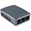
DescriptionThe official case for the Raspberry Pi 4. This case ships as two parts made of ABS plastic with access to all USB, HDMI, Audio/Video, USB and Ethernet ports. In addition, a slot on the bottom gives access to the MicroSD card. The top and bottom parts are press fit and comes in two-tone black and gray.
アズワン品番67-0426-07
 SparkFun USB UART Serial Breakout - CY7C65213SPARKFUN
¥5,498税込¥6,048
1個
33日以内出荷
DescriptionThe CY7C65213 USB to UART serial breakout is designed to provide users with a means to access all available I/O pins on the IC, and to provide a 6-pin UART header that is compatible with other SparkFun breakout boards. This breakout has a m
アズワン品番67-0419-92
 SparkFun Qwiic pHAT Extension for Raspberry Pi 400SPARKFUN
¥1,998税込¥2,198
1個
33日以内出荷
DescriptionThe SparkFun Qwiic pHAT Extension for the Raspberry Pi 400 provides you with a quick and easy solution to access all of the 400's GPIO, stack your favorite HAT right-side up, or connect a Qwiic-enabled device to the I2C bus(GND, 3.3V, SDA
アズワン品番67-0423-40
 SparkFun MicroMod Asset Tracker Carrier BoardSPARKFUN
¥43,980税込¥48,378
1個
33日以内出荷
DescriptionNote - Please read before purchasing!:The MicroMod Asset Tracker uses the "00B" product version of the SARA-R5 module(specifically the SARA-R510M8S-00B-00). LTE NB-IoT Radio Access Technology, and the LTE FDD bands:66, 71, 85 are not suppor
アズワン品番67-0423-27
 MI:pro Protector Case for micro:bit V2SPARKFUN
¥2,398税込¥2,638
1個
33日以内出荷
DescriptionThis MI:pro Protector Case for the BBC micro:bit has been designed to work with both the original micro:bit V1 and the micro:bit V2. These cases feature a four-layer construction style with ability to mount a 2xAAA battery pack to the back of the case while still providing access to all buttons and ports on the micro:bit. Though these cases do protect the micro:bit astoundingly well, the biggest benefit of using the MI:pro is to not accidentally short out the pads on the back of the micro:bit.Construction is simple, requiring only a small flathead screwdriver(at most), and involves layering each plate on top of one another around the micro:bit and screwing it into place. Luckily, the MI:pro Protector case enables easy access to the edge pins at the bottom of the micro:bit, allowing it to still be plugged into an edge connector found on many of our carrier boards. The only board that cannot be used in conjunction with the MI:pro case is the SparkFun gamer:bit due to its edge connector being located in the center of the board.Note:The MI:pro Protector case only includes the parts found in the Includes Tab. This case doesNOTinclude a micro:bit, power source or mounting screws. These items will need to be purchased separately.FeaturesDimensions:Length:65mm.Width:37mm.Depth(without screws):12mm.Depth(with screws):18.5mm.Provides excellent protection to the BBC micro:bit whilst allowing access to the bottom pins.Full access to the A and B buttons on the BBC micro:bit.Attach a battery cage to the rear of the case with the supplied sticky fixer.Full access to pins and connections including the micro USB connector.Clear case material shows the on-board LEDs in perfect clarity.The case is compatible with versions 1 and 2 of the micro:bit.When used in conjunction with a battery holder, micro:bit projects can be fully mobile.
アズワン品番67-0426-13
 MI:pro Mountable Case for micro:bit V2SPARKFUN
¥1,998税込¥2,198
1個
33日以内出荷
DescriptionThe Mountable MI:pro is a simple and compact protective case for the micro:bit. This case has been specifically designed with portability and expansion in mind and is compatible with both the original micro:bit V1 and the micro:bit V2. These cases feature a three-layer construction style with ability to wall-mount the whole assembly onto any surface you want while still providing access to all buttons and ports on the micro:bit. Though these cases do feature wall-mountable tabs, the biggest benefit of using a case is to not accidentally short out the pads on the back of the micro:bit.Construction is simple, requiring only a small flathead screwdriver, and involves layering each plate on top of one another around the micro:bit and screwing it into place. Luckily, the MI:pro case enables easy access to the edge pins at the bottom of the micro:bit, allowing it to still be plugged into an edge connector found on many of our carrier boards. The only board that cannot be used in conjunction with the MI:pro case is the SparkFun gamer:bit due to its edge connector being located in the center of the board.Note:The MI:pro case only includes the parts found in the Includes Tab. This case does NOT include a micro:bit, power source or mounting screws. These items will need to be purchased separately.FeaturesDimensions:Length(minus the mounting brackets on the side):65mm.Length(with the mounting brackets on the side):91mm.Width:37mm.Depth(without screws):9mm.Depth(with screws):14mm.Provides excellent protection to the BBC micro:bit whilst allowing access to the bottom pins.Full access to the A and B buttons on the BBC micro:bit.The mounting points allow you to fix the micro:bit to a surface for sturdy and more permanent installations.Full access to pins and connections including the micro USB connector.Clear case material shows the on-board LEDs in perfect clarity.The case is compatible with versions 1 and 2 of the micro:bit.
アズワン品番67-0426-14
 SparkFun Multiplexer Breakout - 8 Channel 74HC4051SPARKFUN
¥999税込¥1,099
1個
33日以内出荷
DescriptionThe SparkFun Multiplexer Breakout provides access to all pins and features of the 74HC4051, an 8-channel analog multiplexer/demultiplexer. The 74HC4051 allows you to turn four I/O pins into eight multifunctional, individually selectable signals, which can be used to do everything from driving eight LEDs to monitoring eight potentiometers.The 74HC4051 can function as either a multiplexer or a demultiplexer, and it features eight channels of selectable inputs/outputs. The routing of common signal to independent I/O is set by digitally controlling three select lines, which can be set either high or low into one of eight binary combinations.One half of the board breaks out the control signals(E, S0-S2)and common input/output(Z). The other side provides access to all eight independent I/O's(Y0-Y7). Both sides include supply and ground connections(VCC, VEE, GND).Get Started with the 74HC4051 Breakout GuideFeaturesSwitches analog or digital signals8 channels controlled by 3 select inputsWide voltage supply range:2 -- 10VBipolar supply support(e.g., ±5V)Optional enable inputBreadboard compatible breakout
アズワン品番67-0419-95
 SparkFun Cryptographic Co-Processor Breakout - ATECC608A QwiicSPARKFUN
¥1,498税込¥1,648
1個
33日以内出荷
DescriptionProduct Restrictions:To access certain features of the ATECC608A, users will need to contact Microchip and sign an NDA contract to obtain the complete datasheet. Due to the required NDA - technical support, an Arduino library, and hookup guide are not provided for users on this product.The SparkFun ATECC608A Cryptographic Co-processor Breakout allows you to add strong security to your IoT node, edge device, or embedded system. This includesasymmetricauthentication,symmetricAES-128 encryption/decryption, and much more. As stated above, the ATECC608A has limited Arduino support and the complete datasheet is under NDA with Microchip.This breakout board includes two Qwiic ports for plug and play functionality. Utilizing our handy Qwiic system, no soldering is required to connect it to the rest of your system. However, we still have broken out 0.1"-spaced pins in case you prefer to use a breadboard. The ATECC608A chip is capable of many cryptographic processes, including, but not limited to:Creating and securely storing unique asymmetric key pairs based on Elliptic Curve Cryptography(FIPS186-3).AES-128:Encrypt/Decrypt, Galois Field Multiply for GCMCreating and verifying 64-byte digital signatures(from 32-bytes of message data).Creating a shared secret key on a public channel via Elliptic Curve Diffie-Hellman Algorithm.SHA-256 HMAC Hash including off-chip context save/restoreInternal high quality FIPS random number generator.Embedded in the chip is a 10Kb EEPROM array that can be used for storing keys, certificates, data, consumption logging, and security configurations. Access to the sections of memory can then be restricted and the configuration locked to prevent changes. Each ATECC608A Breakout ships with a guaranteed unique 72-bit serial number and includes several security features to prevent physical attacks on the device itself, or logical attacks on the data transmitted between the device.A summary datasheet for the ATECC608A is available here. The full datasheet is under NDA with Microchip. You will need to contact them for access to the entire datasheet. Meanwhile, the ArduinoATECCX08 Library currently only supports the ATECC608A with SAMD21 Arduino boards.We do have much more support for the ATECC508A version of this chip. Please check out our ATECC508A Hookup Guide and Arduino Library(which includes six examples). This will get you familiar with the basics of elliptic curve cryptography and signing/verifying data with the ATECC508A version of the chip.Note:The I2C address of the ATECC608A is 0x60 and is software-configurable to any address. A multiplexer/Mux is required to communicate to multiple ATECC608A sensors at the default address when on a single bus. If you need to use more than one ATECC608A sensor at the default address, consider using the Qwiic Mux Breakout.Note:The ATECC608A can be only configured once before it isPERMANENTLYlocked. It is advisable that users purchase multiple boards in order to use other configurations and explore the advanced functions of the ATECC608A.Additionally, this boardIScapable of encrypting and decrypting data. However, to access these additional features, you will need to contact Microchip and sign an NDA contract to obtain the complete datasheet.It is recommended that an SparkFun RedBoard Turbo - SAMD21 Development Board is used with this product due to the buffer size required on the I2C bus.The SparkFun Qwiic Connect System is an ecosystem of I2C sensors, actuators, shields and cables that make prototyping faster and less prone to error. All Qwiic-enabled boards use a common 1mm pitch, 4-pin JST connector. This reduces the amount of required PCB space, and polarized connections mean you can't hook it up wrong.FeaturesOperating Voltage:2.0V-5.5V(Default on Qwiic System:3.3V)Active Current Draw(for ATECC608A):16 mASleep Current(for ATECC608A):<150 nAGuaranteed Unique 72-bit Serial Number10 Kb EEPROM Memory for Keys, Certificates, and DataStorage for up to 16 Keys256-bit Key LengthInternal High-Quality FIPS Random Number Generator(RNG)Configurable I2C Address(7-bit):0x60(Default)
アズワン品番67-0423-59
 Sweepy 2.0 69mmSPARKFUN
¥20,980税込¥23,078
1個
33日以内出荷
DescriptionSweepy 2.0 is our new Dust Boot made from clear polycarbonate.Version 2.0 features a number of enhancements, that stem from customer feedback. These include:Sweepy 65 V2 - now can now travel up and down the spindle body allowing greater flexibility when millingNow fits a 2.5" Shopvac as standardIncludes adapters for:2.5" direct hose2.25" shop vac36mm Festool/FeinIncludes our affectionally-named "Winston" a clear brush free base for 3d carving and video makingThis 69mm size is for the Dewalt spindles.Sweepy mounts directly to your spindle and is clamped with a machined quick-release. The compact design means that no travel is lost, and it works with any Shapeoko Z-axis with no adapters. The lower half is detachable and held in place using neodymium magnets, which means that the top half remains in place while the lower half detaches for easy access when changing bits.(For the legal sticklers out there, the Shapeoko and Compact Router shown in the photos are not included with Sweepy.)
アズワン品番67-0429-12
 Macchina A0 OBD-II Development ModuleSPARKFUN
¥30,980税込¥34,078
1個
33日以内出荷
DescriptionThe A0 in the latest in Macchina's line of OBD-II interfaces. The A0 uses the power of the ESP32 BLE and WiFi module to allow for wireless access to the OBD-II port most modern cars have.The Macchina A0 module plugs directly into the OBD-II port found in most modern cars and receives its power from the port. From there, one can interface with the device through a few different methods. The easiest is with software such as SavvyCAN, Torque Lite on Android. Besides getting all on board diagnostic information, you're able to control certain aspects of the car and create cool projects such as dash-mounted, shift lights. The A0 can also be programmed in the Arduino IDE, so there's plenty of possibilities to customize the device for what you want to do with your car!FeaturesODB-II compatibility with all modern cars(1996 or newer)Pre-loaded with SavvyCAN for plug and play(wireless!)reverse engineeringWiFi and Bluetooth(R)FunctionalityESP32 ProcessorSuper bright RGB LEDCAN Communication FunctionalityProgrammable with the Arduino IDE
アズワン品番67-0423-39
 Cherry MX Switch BreakoutSPARKFUN
¥799税込¥879
1個
33日以内出荷
DescriptionCherry MX Keyswitches are top-of-the-line mechanical keyboard switches. They're satisfyingly "clicky", reliable up to tens-of-millions of key presses, and a standard in gaming and programming keyboards across the globe. With the SparkFun Cherry MX Switch Breakout we have made the switches more easily adaptable to breadboard or perfboard-based projects. The Cherry MX Switch Breakout is a perfect prototyping tool for projects ranging from a single-key user-input to fully-custom 101-key keyboards.In addition to breaking out the switch contacts to breadboard-compatible headers, the Cherry MX Switch Breakout also provides access to an optional switch-mounted LED. Plus, the pin break-outs are designed with keyboard matrix-ing in mind, so you can interconnect as many boards as you'd like into a row-column configuration, keeping the I/O-pin requirements as low as possible.Note:If you are looking for a Cherry MX Switch to use with this breakout, we've got you covered! CLICK HERE!Get Started with the Cherry MX Switch GuideFeaturesSupport for 3mm LEDFootprint for LED current-limiting resistorFootprint for switch-isolating diodeChain-able in row/column matricesDesigned to match standard key spacing and keyboard row offsets
アズワン品番67-0419-91
 SparkFun FM Tuner Evaluation Board - Si4703SPARKFUN
¥7,298税込¥8,028
1個
33日以内出荷
DescriptionThis is an evaluation board for the Silicon Laboratories Si4703 FM tuner chip. Beyond enabling you to tune in to FM radio stations, the Si4703 is also capable of detecting and processing both Radio Data Service(RDS)and Radio Broadcast Data Service(RBDS)information. The Si4703 even does a very good job of filtering and carrier detection. It also enables data such as the station ID and song name to be displayed to the user.Using this board, you will be able to pick up multiple stations just as well as with a standard FM radio. The board breaks out all major pins and makes it easy to incorporate this great chip into your next radio project. The power bus, the 3.3V and GND pins are broken out For communication. The breakout provides access to SDIO and SCLK for I2C communication while RST can be used for easy resetting. The SEN pin enables the user to change the mode of functionality of the IC. The last two pins broken out are GPIO1 and GPIO2 which can be used as general input/output pins, but also can be used for things like the RDS ready, seeking or tuning functions.Keep in mind, by plugging headphones into the 3.5mm audio jack, you effectively use the cable in your headphones as an antenna! Therefore, this board does not require an external antenna if using headphones or a 3.5mm audio cable longer than 3 feet.
アズワン品番67-0429-34
 SparkFun Qwiic micro:bit BreakoutSPARKFUN
¥1,898税込¥2,088
1個
33日以内出荷
DescriptionThe SparkFun Qwiic micro:bit Breakout is a board that connects to the BBC micro:bit and expands the capabilities of the development platform by providing access to more pins and allowing for connections to the I2C and SPI buses. This breakout board for the micro:bit's edge connector allows intermediate and advanced users to connect the micro:bit to breadboards and other Qwiic sensors, motors, LEDs and more.The micro:bit on its own has three digital/analog input/output rings available for you to use initially with alligator clips. With the micro:bit Breakout we have broken out all 21 GPIO, power and ground-to-pin outs in a 0.1" formation and with two individual Qwiic Connectors. With this breakout you will be able to unlock the full potential of your micro:bit!Note:No micro:bit or headers are included with this breakout; they will need to be purchased separately. If you would like a micro:bit breakout with headers already soldered on, be sure to check out this board's sibling.The SparkFun Qwiic Connect System is an ecosystem of I2C sensors, actuators, shields and cables that make prototyping faster and less prone to error. All Qwiic-enabled boards use a common 1mm pitch, 4-pin JST connector. This reduces the amount of required PCB space, and polarized connections mean you can't hook it up wrong.Get Started with the Qwiic micro:bit Breakout Guide
アズワン品番67-0420-12
 SparkFun MicroMod Update ToolSPARKFUN
¥1,798税込¥1,978
1個
33日以内出荷
DescriptionThe SparkFun MicroMod Update Tool is built to interface with the MicroMod Asset Tracker Carrier Board and also makes it simple to communicate directly with the u-blox SARA-R510M8S module using u-blox's sophisticated m-center cellular evaluation software. If you're familiar with u-center, u-blox's GNSS evaluation software, you'll know how excellent their software is. m-center is every bit as good. Attach a USB-C cable and away you go!The Update Tool is not a full MicroMod Processor Board, it is much simpler than that. It has a CH340C USB-Serial converter on it which gives you full access to all eight pins of the SARA-R5's UART interface via the Asset Tracker's USB-C connector. Think of it as a bridge from USB to serial.The Update Tool features eight pairs of Plated Through Hole connections for the UART signals. You can use these to connect directly to the SARA UART using 3.3V signals if you want to. The split pads on the rear of the Tool can be opened to isolate the CH340C completely; the pins nearest the M.2 will link straight to the SARA UART.Get Started with the MicroMod Update Tool Hookup GuideFeaturesCH340C USB-Serial converterEight pairs of Plated Through Hole connections with split pad jumper links for:Serial Transmit(TX)Serial Receive(RX)Request To Send(RTS)Clear To Send(CTS)Data Terminal Ready(DTR)Data Set Ready(DSR)Ring Indicator(RI)Data Carrier Detect(DCD)LED indicator for:Power(3.3V)
アズワン品番67-0423-52
 SparkFun weather:bit - micro:bit Carrier Board QwiicSPARKFUN
¥5,998税込¥6,598
1個
33日以内出荷
DescriptionThe SparkFun weather:bit is a fully loaded "carrier" board for the micro:bit that, when combined with the micro:bit, provides you with a fully functional weather station. With the weather:bit you will have access to barometric pressure, relative humidity and temperature readings. There are also connections on this carrier board to optional sensors such as wind speed, direction, rain gauge and soil readings! In this version we have also added a vertical Qwiic connector. The micro:bit has a lot of features and a lot of potential for weather data collection.The weather:bit connects to the micro:bit via an edge connector at the top of the board, making setup easy. This creates a handy way to swap out micro:bits for programming, while still providing reliable connections to all of the different pins on the micro:bit. We have also included serial and I2C headers on the weather:bit for optimized connectivity if you so choose.The micro:bit is a pocket-sized computer that lets you get creative with digital technology. Between the micro:bit and our shield-like bit boards you can do almost anything while coding, customizing and controlling your micro:bit from almost anywhere! You can use your micro:bit for all sorts of unique creations, from robots to musical instruments and more. At half the size of a credit card, this versatile board has vast potential!Note:The SparkFun weather:bit doesNOTinclude a micro:bit board. The micro:bit will need to be purchased separately.Get started with the weather:bit GuideFeaturesOnboard temperature, humidity, and pressure sensorConnectors(PTH and screw terminal)for soil moisture and soil temperatureConnectors(RJ11)for wind speed, direction and rainfall gaugesEdge connector for easy micro:bit integrationVertical Qwiic connectorHeaders for Serial and I2C communication
アズワン品番67-0422-94
 SparkFun 2D Barcode Scanner BreakoutSPARKFUN
¥20,980税込¥23,078
1個
欠品中
DescriptionThe SparkFun 2D Barcode Scanner Breakout is a nifty little breakout board featuring the DE2120 barcode scanner module from DYScan. The DE2120 reads 20 different barcode symbologies(both 1D and 2D)using a camera coupled with on-board image processing to identify and decode everything from UPC codes to QR codes. The module also features two LEDs:one for illumination and one to project the red line that you're used to seeing from laser-based scanners.This breakout board makes it easy to explore all of the capabilities of the DE2120 without dealing with finicky flat flex cables. The scanner's USB interface is exposed via the on-board USB-C connector. A buzzer and status LED are connected to the module through appropriate drive circuits and a push button tactile switch is provided on the "trigger" pin. When you're ready to incorporate the module into your embedded project, you can leverage the 5 pin header for direct access to the TTL serial pins, power pins, and trigger input.The module can be configured either by using the serial interface or by scanning command barcodes found in the Settings Manual.All keyboard, HID, and serial can be transmitted over the single USB-C connector. The DE2120 has the unique ability to enumerate all three protocols including a CDC serial driver so the device appears as a standard COM port.Get Started with the 2D Barcode Scanner Breakout Hookup GuideFeaturesUSB-C Connector for USB HID Interface and Virtual COM portReads 20 different symbologies1D SymbologiesUPC-AUPC-EEAN-8EAN-13Code 128GS1-128Code 39Code 93Code 11Interleaved 2-of-5Matrix 2-of-5Industrial 2-of-5CodabarMSIGS1 DataBarDatalogic 2-of-52D SymbologiesQR CodeData MatrixPDF 417Micro PDF 417Aztec Code
アズワン品番67-0430-36
 SparkFun MicroMod ATP Carrier BoardSPARKFUN
¥6,298税込¥6,928
1個
33日以内出荷
DescriptionAccess all the pins(i.e. ATP)of the MicroMod Processor Boards with the SparkFun MicroMod ATP Carrier Board! This board breaks out the MicroMod Processor Board's pins on the M.2 connector to 0.1" spaced female headers and PTH pads on the edge of the board. This Carrier Board is great if you're interested in testing out different MicroMod Processor Boards for your application.A modern USB-C connector makes programming easy. In addition to the pins broken out, two separate Qwiic-enabled I2C ports allow you to easily daisy chain Qwiic-enabled devices. We've exposed the SWD pins for more advanced users who prefer to use the power and speed of professional tools. A USB-A connector is provided for Processor Boards that have USB Host support. A backup battery is provided for processor boards with RTC. If you need a "lot" of GPIO with a simple-to-program, ready for market module, the ATP is the fix you need. We've even added a convenient jumper to measure the current consumption for low power testing.MicroMod is a modular interface ecosystem that connects a microcontroller "processor board" to various "carrier board" peripherals. Utilizing the M.2 standard, the MicroMod standard is designed to easily swap out processors on the fly. Pair a specialized carrier board for the project you need with your choice of compatible processor!Get Started with the MicroMod ATP Carrier Board GuideFeaturesM.2 ConnectorOperating Voltage Range~3.3V to 6.0V(via VIN to AP7361C 3.3V Voltage Regulator)3.3V(via 3V3)Ports [1]1x USB type C1x USB type A Host2x Qwiic Enabled I2C1x CAN1x I2S2x SPI2x UARTs2x Dedicated Analog Pins2x Dedicated PWM Pins2x Dedicated Digital Pins12x General Purpose Input Output Pins1x SWD 2x5 header1mAh battery backup for RTCButtonsResetBootLEDsPower3.3VPhillips #0 M2.5x3mm screw included[1] Note:Depending on the design of the Processor Board, not all the pins may be accessible.
アズワン品番67-0423-18
 SparkFun Spectral Sensor Breakout - AS7263 NIR QwiicSPARKFUN
¥9,998税込¥10,998
1個
欠品中
DescriptionThe SparkFun AS7263 Near Infrared(NIR)Spectral Sensor Breakout brings spectroscopy to the palm of your hand, making it easier than ever to measure and characterize how different materials absorb and reflect different wavelengths of light. The AS7263 Breakout is unique in its ability to communicate by both an I2C interface and serial interface using AT commands. Hookup is easy, thanks to the Qwiic connectors attached to the board --- simply plug one end of the Qwiic cable into the breakout and the other into one of the Qwiic shields, then stack the board on a development board. You'll be ready to upload a sketch to start taking spectroscopy measurements in no time.The AS7263 spectrometer detects wavelengths in the visible range at 610, 680, 730, 760, 810 and 860nm of light, each with 20nm of full-width half-max detection. The board also has multiple ways for you to illuminate objects that you will try to measure for a more accurate spectroscopy reading. There is an onboard LED that has been picked out specifically for this task, as well as two pins to solder your own LED into.Note:The I2C address of the AS7263 is 0x49 and is hardware defined. A multiplexer/Mux is required to communicate to multiple AS7263 sensors on a single bus. If you need to use more than one AS7263 sensor consider using the Qwiic Mux Breakout.The SparkFun Qwiic Connect System is an ecosystem of I2C sensors, actuators, shields and cables that make prototyping faster and less prone to error. All Qwiic-enabled boards use a common 1mm pitch, 4-pin JST connector. This reduces the amount of required PCB space, and polarized connections mean you can't hook it up wrong.Get Started with the SparkFun AS726X Spectral Sensor Breakout GuideFeatures6 near-IR channels:610nm, 680nm, 730nm, 760nm, 810nm and 860nm, each with 20nm FWHMNIR filter set realized by silicon interference filters16-bit ADC with digital accessProgrammable LED drivers2.7V to 3.6V with I2C interface2x Qwiic connectors
アズワン品番67-0426-70
 Himax CMOS Imaging Camera - HM01B0SPARKFUN
¥3,698税込¥4,068
1個
33日以内出荷
DescriptionThe HM01B0 from Himax Imaging is an ultra low power CMOS Monochrome Image Sensor that enables the integration of an "Always On" camera for computer vision applications such as gestures, intelligent ambient light and proximity sensing, tracking and object identification. The sensor allows the sensor to consume very low power of <2mW at QVGA 30FPS. This low power consumption and vision applications camera comes with a ribbon cable that mates to the camera connector populated on the following products:MicroMod Machine Learning Carrier BoardArtemis Development KitEdge Development Board - Apollo3 BlueThe HM01B0 contains 320×320 pixel resolution and supports a 320×240 window mode which can be readout at a maximum frame rate of 60FPS, and a 2×2 monochrome binning mode with a maximum frame rate of 120FPS. The video data is transferred over a configurable 1bit, 4bit or 8bit interface with support for frame and line synchronization. The sensor integrates black level calibration circuit, automatic exposure and gain control loop, self-oscillator and motion detection circuit with interrupt output to reduce host computation and commands to the sensor to optimize the system power consumption.FeaturesImage SensorUltra Low Power Image Sensor(ULPIS)designed for Always On vision devices and applicationsHigh sensitivity 3.6μ BrightSenseTM pixel technology320×320 active pixel resolution with support for QVGA window, vertical flip and horizontal mirror readoutProgrammable black level calibration target, frame size, frame rate, exposure, analog gain(up to 8x)and digital gain(up to 4x)Automatic exposure and gain control loop with support for 50 / 60Hz flicker avoidanceFlexible 1bit, 4bit and 8bit video data interface with video frame and line syncMotion Detection circuit with programmable ROI and detection threshold with digital output to serve as an interruptOn-chip self oscillatorI2C 2-wire serial interface for register accessHigh CRA for low profile module designSensor ParametersActive Pixel Array 320×320Pixel Size 3.6 μm×3.6 μmFull Image Area 1152 μm×1152 μmDiagonal(Optical Format)1.63 mm(1/11″)Scan Mode:ProgressiveShutter Type:Electronic Rolling ShutterFrame Rate MAX 51 fps @ 320×320, 60 fps @ 320×240(QVGA)CRA(maximum)30℃Sensor SpecificationsSupply Voltage:Analog - 2.8 V, Digital - 1.5V(Internal LDO:1.5V - 2.8V), I/O - 1.5 - 2.8VInput Reference Clock:3 - 50 MHzSerial Interface(I2C):2-wire, 400 KHz max.Video Data Interface:1b, 4b, 8b with frame / line SYNCOutput Clock Rate MAX:50 MHz for 1bit, 12.5 MHz for 4bit, 6.25 MHz for 8bitEst. Power Consumption(include IO with 5pF load):QVGA 60FPS(Typical)<4 mWQVGA 30FPS(Typical)<2 mW
アズワン品番67-0427-08
 SparkFun Thing Plus - RP2040SPARKFUN
¥6,698税込¥7,368
1個
33日以内出荷
DescriptionThe SparkFun Thing Plus - RP2040 is a low-cost, high performance board with flexible digital interfaces featuring the Raspberry Pi Foundation's RP2040 microcontroller. Besides the Thing Plus orFeatherfootprint(with 18 GPIO pins), the board also includes an SD card slot, 16MB(128Mbit)flash memory, a JST single cell battery connector(with a charging circuit and fuel gauge sensor), an addressable WS2812 RGB LED, JTAG PTH pins, four(4-40 screw)mounting holes, and our signature Qwiic connector.The RP2040 contains two ARM Cortex-M0+ processors(up to 133MHz)and features:264kB of embedded SRAM in six banks6 dedicated IO for SPI Flash(supporting XIP)30 multifunction GPIO:Dedicated hardware for commonly used peripheralsProgrammable IO for extended peripheral supportFour 12-bit ADC channels with internal temperature sensor(up to 0.5 MSa/s)USB 1.1 Host/Device functionalityThe RP2040 is supported with both C/C++ and MicroPython cross-platform development environments, including easy access to runtime debugging. It has UF2 boot and floating-point routines baked into the chip. While the chip has a large amount of internal RAM, the board includes an additional 16MB of external QSPI flash memory to store program code.The SparkFun Qwiic Connect System is an ecosystem of I2C sensors, actuators, shields and cables that make prototyping faster and less prone to error. All Qwiic-enabled boards use a common 1mm pitch, 4-pin JST connector. This reduces the amount of required PCB space, and polarized connections mean you can't hook it up wrong.Get Started With the Thing Plus RP2040 Hookup GuideFeaturesSparkFun Thing Plus - RP2040 FeaturesRaspberry Pi Foundation's RP2040 microcontroller16MB QSPI Flash MemoryJTAG PTH PinsThing Plus(or Feather)Form-Factor:18[1]x Multifunctional GPIO Pins[2]Four available 12-bit ADC channels with internal temperature sensor(500kSa/s)Up to eight 2-channel PWMUp to two UARTsUp to two I2C busesUp to two SPI busesUSB-C Connector:USB 1.1 Host/Device functionality2-pin JST Connector for a LiPo Battery(not included)500mA charging circuitQwiic ConnectorButtons:BootResetLEDs:PWR- Red 3.3V power indicatorCHG- Yellow battery charging indicator25- Blue status/test LED(GPIO 25)WS2812- Addressable RGB LED(GPIO 08)Four Mounting Holes:4-40 screw compatibleDimensions:2.3"×0.9"RP2040 General FeaturesDual Cortex M0+ processors, up to 133 MHz264 kB of embedded SRAM in 6 banks6 dedicated IO for QSPI flash, supporting execute in place(XIP)30 programmable IO for extended peripheral supportSWD interfaceTimer with 4 alarmsReal time counter(RTC)USB 1.1 Host/Device functionalitySupported programming languagesMicroPythonC/C++1.Note:GPIO 08is not included in this count, as it passes through the WS2812 addressable RGB LED first.GPIO 07andGPIO 23are counted as a single GPIO because they are tied together.2.Note:The GPIO pins are programmable so you can reconfigure the pins! Check out the RP2040 datasheet for more information on the GPIO functionality.
アズワン品番67-0423-56
 SparkFun RTK SurveyorSPARKFUN
¥129,800税込¥142,780
1個
33日以内出荷
DescriptionThe SparkFun RTK Surveyor is an easy to use GNSS receiver for centimeter-level positioning. Perfect for surveying, this preprogrammed device can also be used for autonomous driving, navigation, asset tracking and any other application where there is a clear view of the sky. The RTK Surveyor can also be used as a base station. With the flick of a switch, two RTK Surveyors can be used to create an RTK system capable of 14mm horizontal positional accuracy. The built-in Bluetooth(R)connection via an ESP32 WROOM enables the user to use the RTK Surveyor with their choice of GIS application on a phone or tablet. The built in battery allows field use for up to four hours and is compatible with common USB battery banks.This device can be used in four modes:GNSS Positioning(~30cm accuracy)GNSS Positioning with RTK(1.4cm accuracy)GNSS Base StationGNSS Base Station NTRIP ServerIn Position mode the device receives L1/L2 signals from a user-provided antenna and the high-grade GNSS receiver provides lat/long and altitude with accuracies around 300mm.In Positioning with RTK mode the device receives L1/L2 signals from the antenna and correction data from a base station. The correction data can be obtained from a cellular link to online correction sources or over a radio link to a 2nd RTK Surveyor setup as a base station.In Base Station mode the device is mounted to a temporary position(like a tripod)and begins transmitting correction data over a radio or internet connection. A base is often used in conjunction with a second unit set to 'Positioning with RTK' to obtain the 14mm relative accuracy.In Base Station NTRIP Server mode the device is mounted to a semi or permanently fixed position(like a roof)and connects over WiFi to transmit the correction data to a NTRIP caster so that any rover can access the correction data over a cellular or internet connection. This type of base is a very easy way to setup a very precise absolute correction source.Two cables are provided with the RTK Surveyor allowing a user to plug on our easy to use Serial Telemetry Radios or their own radio link. If a local correction source is within 10km, a user can also use their phone to provide correction data over the Bluetooth(R)link(no external radio needed!).Note:The SparkFun RTK Surveyor is just the enclosed device and does NOT include an antenna, serial telemetry radio, or associated mounting pieces. These items will need to be purchased separately from the Hookup Accessories below.Get Started With the SparkFun RTK Surveyor GuideFeaturesGNSS Receiver:ZED-F9PConcurrent reception of GPS, GLONASS, Galileo and BeiDouReceives both L1C/A and L2C bandsCurrent:68mA - 130mA(varies with constellations and tracking state)Time to First Fix:25s(cold), 2s(hot)Max Navigation Rate:PVT(basic location over UBX binary protocol)- 25HzRTK - 20HzRaw - 25HzHorizontal Position Accuracy:2.5m without RTK0.010m with RTKMax Altitude:50km(31 miles)Max Velocity:500m/s(1118mph)Bluetooth(R)Transceiver:ESP32 WROOMXtensa(R)dual-core 32-bit LX6 microprocessorUp to 240MHz clock frequency16MB of flash storage520kB internal SRAMIntegrated 802.11 BGN WiFi transceiverIntegrated dual-mode Bluetooth(R)(classic and BLE)Hardware accelerated encryption(AES, SHA2, ECC, RSA-4096)2.5 μA deep sleep currentOverall DeviceInternal Battery:LiPo 1000mAh with 500mA chargingRadio Port:3.3V TTL Serial(57600bps RTCM TX/RX)Data Port:3.3V TTL Serial(115200bps NMEA)Weight:132g(entire device including battery)Dimensions:118mm×79mm×30mm(4.7in×3.1in×1.2in)1x Qwiic Connector1x microSD Socket for optional loggingChanges:This version(which replaces SPX-17369)uses a reinforced edge mount SMA connector for better resiliency when a fixed 'stub' antenna is used.
アズワン品番67-0423-95
 SparkFun gator:log - micro:bit Accessory BoardSPARKFUN
¥4,398税込¥4,838
1個
33日以内出荷
DescriptionThe gator:log is the perfect data logging tool for your next experiment. With the automation of the data collection process, gone are the days of rushing around with a pen and composition notebook to simultaneously record data and your observations. Now, you only need to sit back and observe your experiment.The gator:log allows a student(s)to focus more on what is happening in the experiment than watching a thermometer or sensor readout. Additionally, a micro:bit can still be used to provide a graphical display for observing changes in data, when a sensor readout is required. If tied in conjunction with the gator:RTC, stop watches on time based experiments can become a thing of the past too(with the added benefit of more accurate timing results)!The micro:bit is a pocket-sized computer that lets you get creative with digital technology. Between the micro:bit and our shield-like bit boards you can do almost anything while coding, customizing and controlling your micro:bit from almost anywhere! You can use your micro:bit for all sorts of unique creations, from robots to musical instruments and more. At half the size of a credit card, this versatile board has vast potential!Get Started with the SparkFun gator:log Hookup GuideFeaturesATmega328P microcontrollerμSD(micro SD)card slot for μSD card for data storageTwo status indicator LEDsSerial connection via RX and TX padsGND and 3V3 pads for 3.3V power connection
アズワン品番67-0422-76
 Raspberry Pi 400 Personal Computer Unit OnlySPARKFUN
¥28,980税込¥31,878
1個
33日以内出荷
DescriptionThe Raspberry Pi 400 is a complete Raspberry Pi 4-based personal computer, integrated into a keyboard. By incorporating the board into a keyboard, it removes the need for a case and other accessories normally needed to run a Raspberry and
アズワン品番67-0423-37
 Qwiic Cable - Grove Adapter 100mmSPARKFUN
¥709税込¥780
1個
33日以内出荷
DescriptionWith the SparkFun Qwiic Connect System expanding every day, we want to make sure it becomes as accessible as possible but we understand there are other systems that can compliment it out there. The Qwiic to Grove Adapter Cable allows interoperability between the SparkFun Qwiic Connect System and the I2C based Grove boards from Seeed Studio. Now you can plug Seeed Studio boards you may have onto the Qwiic bus or you can use this cable to introduce Qwiic sensors, inputs, and outputs into your Grove system.Note:The Grove system has a variety of different signal systems that use the same connector. This cableonlyworks with the I2C variety.The SparkFun Qwiic connect system is an ecosystem of I2C sensors, actuators, shields and cables that make prototyping faster and less prone to error. All Qwiic-enabled boards use a common 1mm pitch, 4-pin JST connector. This reduces the amount of required PCB space, and polarized connections mean you can't hook it up wrong.FeaturesLength:100mm
アズワン品番67-0425-61
 SparkFun Qwiic Thermocouple Amplifier - MCP9600 PCC ConnectorSPARKFUN
¥17,980税込¥19,778
1個
欠品中
DescriptionThe MCP9600 Breakout is a high accuracy Thermocouple Amplifier equipped with an I2C interface, accessed over our Qwiic system. Inside the chip are two temperature sensors, one for the thermocouple itself(the hot junction)and one for the chi
アズワン品番67-0427-14
 Nomad Flip JigSPARKFUN
¥42,980税込¥47,278
1個
33日以内出荷
DescriptionThe Nomad Flip Jig is a handy accessory for your Nomad 883 Pro that allows you to cut both sides of a part while maintaining perfect alignment. Each one of these jigs is precision machined to mount to the Nomad's table and uses the CNC's bu
アズワン品番67-0428-34
 BitZero V2 for ShapeokoSPARKFUN
¥42,980税込¥47,278
1個
33日以内出荷
DescriptionThe BitZero from Carbide 3D is a small accessory piece for your Shapeoko CNC machine meant to assist in finding the edges, or datums of the part you are milling. This part is an active probe, and when contacted to ground, communicates its p
アズワン品番67-0428-98
 Raspberry Pi 400 Personal Computer KitSPARKFUN
¥41,980税込¥46,178
1個
33日以内出荷
DescriptionThe Raspberry Pi 400 is a complete Raspberry Pi 4-based personal computer, integrated into a keyboard. By incorporating the board into a keyboard, it removes the need for a case and other accessories normally needed to run a Raspberry and
アズワン品番67-0424-62
 SparkFun GPS Breakout - NEO-M9N, SMA QwiicSPARKFUN
¥22,980税込¥25,278
1個
33日以内出荷
DescriptionThe SparkFun NEO-M9N GPS Breakout is a high quality GPS board with equally impressive configuration options including SMA. The NEO-M9N module is a 92-channel u-blox M9 engine GNSS receiver, meaning it can receive signals from the GPS, GLONASS, Galileo, and BeiDou constellations with ~1.5 meter accuracy. This breakout supports concurrent reception of four GNSS. This maximizes position accuracy in challenging conditions increasing, precision and decreases lock time; and thanks to the onboard rechargeable battery, you'll have backup power enabling the GPS to get a hot lock within seconds! Additionally, this u-blox receiver supports I2C(u-blox calls this Display Data Channel)which makes it perfect for the Qwiic compatibility so we don't have to use up our precious UART ports. Utilizing our handy Qwiic system, no soldering is required to connect it to the rest of your system. However, we still have broken out 0.1"-spaced pins in case you prefer to use a breadboard.The NEO-M9N module detects jamming and spoofing events and can report them to the host, so that the system can react to such events. A SAW(Surface Acoustic Wave)filter combined with an LNA(Low Noise Amplifier)in the RF path is integrated into the NEO-M9N module which allows normal operation even under strong RF interferences.U-blox based GPS products are configurable using the popular, but dense, windows program called u-center. Plenty of different functions can be configured on the NEO-M9N:baud rates, update rates, geofencing, spoofing detection, external interrupts, SBAS/D-GPS, etc. All of this can be done within the SparkFun Arduino Library!The SparkFun NEO-M9N GPS Breakout is also equipped with an on-board rechargeable battery that provides power to the RTC on the NEO-M9N. This reduces the time-to-first fix from a cold start(~24s)to a hot start(~2s). The battery will maintain RTC and GNSS orbit data without being connected to power for plenty of time.This product requires an antenna:Be sure to check out the related products/hookup accessories and pick a suitable SMA antenna for your project.The SparkFun Qwiic Connect System is an ecosystem of I2C sensors, actuators, shields and cables that make prototyping faster and less prone to error. All Qwiic-enabled boards use a common 1mm pitch, 4-pin JST connector. This reduces the amount of required PCB space, and polarized connections mean you can't hook it up wrong.The NEO-M9N GPS Breakout can also be automatically detected, scanned, configured, and logged using the OpenLog Artemis datalogger system. No programming, soldering, or setup required!Get Started With the SparkFun NEO-M9N GPS GuideFeaturesIntegrated SMA connector for use with antenna of your choice92-Channel GNSS Receiver1.5m Horizontal Accuracy25Hz Max Update Rate(four concurrent GNSS)Time-To-First-Fix:Cold:24sHot:2sMax Altitude:80,000mMax G:≦4Max Velocity:500m/sVelocity Accuracy:0.05m/sHeading Accuracy:0.3 degreesTime Pulse Accuracy:30ns3.3V VCC and I/OCurrent Consumption:~31mA Tracking GPS+GLONASSSoftware ConfigurableGeofencingOdometerSpoofing DetectionExternal InterruptPin ControlLow Power ModeMany others!Supports NMEA, UBX, and RTCM protocols over UART or I2C interfaces
アズワン品番67-0423-87
 Nomad Low Profile ViseSPARKFUN
¥42,980税込¥47,278
1個
33日以内出荷
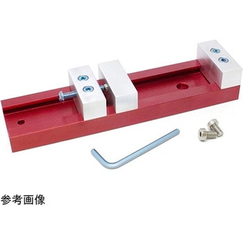
DescriptionThis Low Profile Vise provides you with a compact workholding accessory for the Nomad 883 Pro. Each one of these vises are made from scratch, in-house at Carbide 3D, and includes everything you need to attach it to your Nomad. With the Low Profile Vise you will be able to create miniature and small silhouette milling projects.The Low Profile Vise has a maximum clamping width of 6.5in(~165mm)and is only 8in(~203mm)long and 2in(~50mm)wide. It should go without saying that this vise will easily provide you the ability to mill and fabricate more unique objects!
アズワン品番67-0428-33
 Xcelite 8-in-1 Screwdriver SetSPARKFUN
¥8,998税込¥9,898
1個
33日以内出荷
DescriptionThe Xcelite 8-in-1 Screwdriver Set provides eight high-quality bits in a single ergonomic tool. Each bit is easily accessible with a spring-loaded magnetic housing that holds the seven included bits you aren't currently using. Though the screwdriver set includes eight unique bits, the end of the shaft features a 0.25" hex driver that can fit most of your existing 1/4" bits. With a strong magnetic hold and no-roll handle design, this is one of the best all-in-one tools we have used!The shaft of this multiple-tip driver is made from a chrome-molybdenum vanadium steel that makes for great durability and longevity.
アズワン品番67-0428-23
 USB to TTL Serial Cable 5V VCCSPARKFUN
¥5,198税込¥5,718
1個
欠品中
DescriptionThis is a USB to TTL Serial Cable which allows for a simple way to connect TTL interface devices to USB. The I/O pins of this cable are configured to operate at 3.3V specifically with a Raspberry Pi with each serial pin broken apart. Thanks to its separated pins, this cable is a perfect candidate for powering, connecting, and accessing the login and debug console on an older-version Raspberry Pi.The FTDI cable is designed around an FT232, which is housed in a USB-A connector. The other side of the cable is terminated with a separated 4-pin connector with the following pinout:RX(Yellow), TX(Orange), VCC(5V)(Red), and GND(Black). A link to the FTDI drivers can be found in theDocumentssection above.Note:Please be aware that while the I/O pins in this cableoperate at 3.3V, the VCC pin is 5V. The VCC pin is NOT 3.3V like theI/O pins.
アズワン品番67-0420-67
 SparkFun MicroMod Qwiic Carrier Board - DoubleSPARKFUN
¥4,298税込¥4,728
1個
33日以内出荷
DescriptionThe MicroMod Qwiic Carrier Board can be used to rapidly prototype with other Qwiic devices. The MicroMod M.2 socket provides users the freedom to experiment with any processor board in the MicroMod ecosystem. This board also features two Qwiic connectors and eight 4-40 screw inserts to connect and mount Qwiic devices.This version of the SparkFun MicroMod Qwiic Carrier Board features two ports for our standard 1in. by 1in. Qwiic breakouts. However, you aren't beholden to attaching just a duo of Qwiic breakouts since you are able to stack the boards on top of each other, allowing you to hook up a full circuit of Qwiic sensors and accessories to fully utilize your next project!MicroMod is a modular interface ecosystem that connects a microcontroller "processor board" to various "carrier board" peripherals. Utilizing the M.2 standard, the MicroMod standard is designed to easily swap out processors on the fly. Pair a specialized carrier board for the project you need with your choice of compatible processor!Get Started With the MicroMod Qwiic Carrier Board GuideFeaturesM.2 MicroMod(Processor Board)ConnectorUSB-C Connector3.3V 1A Voltage RegulatorQwiic ConnectorsBoot/Reset ButtonsCharge CircuitEight 4-40 Inserts
アズワン品番67-0423-51
 SparkFun MicroMod Qwiic Carrier Board - SingleSPARKFUN
¥3,500税込¥3,850
1個
33日以内出荷
DescriptionThe MicroMod Qwiic Carrier Board can be used to rapidly prototype with other Qwiic devices. The MicroMod M.2 socket provides users the freedom to experiment with any processor board in the MicroMod ecosystem. This board also features two Qwiic connectors and four 4-40 screw inserts to connect and mount Qwiic devices.This version of the SparkFun MicroMod Qwiic Carrier Board features a single port for our standard 1in. by 1in. Qwiic Breakouts. However, you aren't beholden to attaching just one Qwiic breakout since you are able to stack the boards on top of each other, allowing you to hook up a full circuit of Qwiic sensors and accessories to fully utilize your next project!MicroMod is a modular interface ecosystem that connects a microcontroller "processor board" to various "carrier board" peripherals. Utilizing the M.2 standard, the MicroMod standard is designed to easily swap out processors on the fly. Pair a specialized carrier board for the project you need with your choice of compatible processor!Get Started With the MicroMod Qwiic Carrier Board GuideFeaturesM.2 MicroMod(Processor Board)ConnectorUSB-C Connector3.3V 1A Voltage RegulatorQwiic ConnectorsBoot/Reset ButtonsCharge CircuitFour 4-40 Inserts
アズワン品番67-0423-50
 SparkFun Configurable OpAmp Board - TSH82SPARKFUN
¥2,298税込¥2,528
1個
欠品中
DescriptionThe SparkFun TSH82 Configurable OpAmp Board was designed to give you the best combination of performance and flexibility that we could achieve by giving you two gain stages, each one independently accessible on the header pins. Each stage is natively configured as an inverting amplifier that can also be strung together to expand the capabilities of the TSH82 from STMicroelectronics. With the use of the jumpers on the back of the board, you can configure each stage for non-inverting operation, differential input, and DC input coupling.Electrically speaking, both stages on this board are identical. The default configuration is inverting with a gain of -4.7 with a bandwidth of almost 10MHz. Input signals are AC coupled, possess an input impedance of 10K with a low frequency cutoff of 15.9Hz. Outputs are also DC coupled, so don't forget to add a capacitor to the output if you're running a single-ended supply and need to strip out the DC component. The board will also operate with a single-ended DC power supply of 4.5V to 12V, or a bipolar supply from +/-2.25V to +/-6V.On the back of the board you'll find 10 solder jumpers that can be used to change the board's performance, but nothing there needs to be changed to use it in it's default state.Get Started With the Configurable OpAmp Board Guide
アズワン品番67-0420-03
 LEDドライバSPARKFUN
¥2,498税込¥2,748
1個
33日以内出荷
DescriptionThis is the FemtoBuck, a small-size single-output constant current LED driver. Each FemtoBuck has the capability to dim a single high-power channel of LEDs from 0-350mA at up to 36V while the dimming control can be either accessed via PWM or analog signal from 0-2.5V. This board is based off of the PicoBuck LED Driver, developed in collaboration with Ethan Zonca, except instead of blending three different LEDs on three different channels the FemtoBuck controls just one.For the FemtoBuck, we've increased the voltage ratings on the parts to allow the input voltage to cover the full 36V range of the AL8805 driver. Since the FemtoBuck is a constant current driver, the current drawn from the supply will drop as supply voltage rises. In general, efficiency of the FemtoBuck is around 95%, depending on the input voltage. On board each FemtoBuck you will find two inputs for both power input and dimming control pins and an area to install a 3.5mm screw terminal. Finally at either side of the board you will find small indents or "ears" which will allow you to use a zip tie to secure the wires to the board after soldering them down. This version of the FemtoBuck is equipped with a small solder jumper that can be closed with a glob of solder to double the output current from 330mA to 660mA.
アズワン品番67-0477-97
 SparkFun Inventor's Kit for micro:bit v2 Lab PackSPARKFUN
¥159,800税込¥175,780
1個
33日以内出荷
DescriptionThe SparkFun Inventor's Kit for micro:bit v2 Lab Pack includes 10 complete micro:bit v2 Inventor's Kits, an SIK Refill Pack and 25 AAA-sized batteries to get your students started in the world of electronics. The SIKs inside the Lab Pack have everything you need, including micro:bit v2s, connector breakouts, breadboards and all the cables and accessories to hook up all the projects listed in our online Experiment Guide.The kit does not require any soldering and is recommended for all users, from beginners to engineering students. We have provided a complete Experiment Guide in the Documents tab for you to check out now! If you are new to teaching electronics or have taught with the original SparkFun Inventor's Kit and are looking for something new, the SIK for micro:bit v2 is the perfect kit for you!SparkFun packages everything educators need to get started with this platform in a variety of classroom and makerspace settings with diverse student populations. The hardware boards, cables and extra parts come pre-packaged, and our online support materials --- including an online Experiment Guide(to be updated)--- help you bring the power of the open source community to your classroom. Examples and curriculum materials are available from SparkFun and Arduino, as well as from other educators involved in this growing maker movement.The micro:bit is a pocket-sized computer that lets you get creative with digital technology. Between the micro:bit and our shield-like bit boards you can do almost anything while coding, customizing and controlling your micro:bit from almost anywhere! You can use your micro:bit for all sorts of unique creations, from robots to musical instruments and more. At half the size of a credit card, this versatile board has vast potential!
アズワン品番67-0424-93
 SparkFun Load Sensor CombinatorSPARKFUN
¥839税込¥923
1個
欠品中
DescriptionThe SparkFun Load Sensor Combinator is a bare PCB that combines four load sensors into a standard four-wire Wheatstone bridge configuration. If you open up an electronic bathroom scale, you'll find a large rat's nest of wires. The Load Sensor Combinator was created to combine the 12 wires found in a bathroom scale into the standard four-wire Wheatstone bridge configuration.This version of the SparkFun Load Sensor Combinator features a few changes that you specifically asked for! We updated the silk on the breakout to read "C/+/-" instead of "R/W/B" and moved the temperature sensor connector away from the standoff hole.You can either use four individual load sensors or simply purchase an off-the-shelf bathroom scale and hack the combinator into it rather than trying to design a base to properly mount four load sensors.This board works great with our Load Cell Amplifier breakout board; the five pins on the edge of the combinator line up directly to the five pins on the amplifier.If your amplifier and supporting electronics are more than a few inches away from the scale, an RJ45 footprint is provided. The four Wheatstone pins(E+/E-/S+/S-)as well as the shield pin are connected to twisted pairs within a standard cheap Ethernet cable. This allows the amplifier board to be placed many feet away from the scale itself.The combinator board also includes a footprint for the DS18B20 one-wire temperature sensor. This allows the user to gather the temperature of the scale in case there is a large variance between the scale and the amplifier. These three pins are accessed through the RJ45 connection as well, allowing remote temperature readings to be gathered over one twisted pair Ethernet cable.NOTE:The SparkFun Load Sensor Combinator will only work with 3 wire load sensors, it is not compatible with 4 wire load cells.
アズワン品番67-0419-93
 SparkFun Qwiic Keypad - 12 ButtonSPARKFUN
¥4,198税込¥4,618
1個
33日以内出荷
DescriptionKeypads are very handy input devices, but who wants to tie up seven GPIO pins, wire up handful of pull-up resistors, and write firmware that wastes valuable processing time scanning the keys for inputs? The SparkFun Qwiic Keypad comes fully assembled and makes the development process for adding 12 button keypad easy. No voltage translation or figuring out which I2C pin is SDA or SCL, just plug and go! Utilizing our handy Qwiic system, no soldering is required to connect it to the rest of your system. However, we still have broken out 0.1"-spaced pins in case you prefer to use breadboard.Each of the keypad's 12 buttons has been labeled 1, 2, 3, 4, 5, 6, 7, 8, 9, 0, *, and and has been formatted to into the same layout as telephone keypad with each keypress resistance ranging between 10 and 150 Ohms. The Qwiic Keypad reads and stores the last 15 button presses in First-In, First-Out(FIFO)stack, so you don't need to constantly poll the keypad from your microcontroller. This information, then, is accessible through the Qwiic interface. The SparkFun Qwiic Keypad even has software configurable I2C address so you can have multiple I2C devices on the same bus.NOTE:The I2C address of the Qwiic Keypad is 0x4B and is jumper selectable to 0x4A(software-configurable to any address). multiplexer/Mux is required to communicate to multiple Qwiic Keypad sensors on single bus. If you need to use more than one Qwiic Keypad sensor consider using the Qwiic Mux Breakout.The SparkFun Qwiic connect system is an ecosystem of I2C sensors, actuators, shields and cables that make prototyping faster and less prone to error. All Qwiic-enabled boards use common 1mm pitch, 4-pin JST connector. This reduces the amount of required PCB space, and polarized connections mean you can't hook it up wrong.Get Started with the SparkFun Qwiic Keypad Hookup GuideFeaturesSoftware Selectable Slave AddressLow Power ATtiny85 controllerButton Presses w/ Time StampDefault I2C Address:0x4B2x Qwiic Connector
アズワン品番67-0421-41