


「apera」の検索結果
特価
本日1月25日(日)は、モノタロウブランドの全商品がキャンペーンコード入力で通常価格より
10%
引き!
キャンペーンコード
000026260116
キャンペーンコードのご利用方法
※特価からの更なる割引はございません
関連キーワード


Description。LIDAR has never looked so good! This is the LIDAR-Lite v3HP, a compact, high-performance optical distance measurement sensor from Garmin(TM). The LIDAR-Lite v3HP is。the。ideal optical ranging solution for drone, robot, or unmanned vehicle applications. Each sensor is housed in a durable, IPX7-rated housing and includes all the core features and user configurability of the popular LIDAR-Lite v3.。The v3HP is very similar in function to that of the v3 but it can now sample faster at rates greater than 1kHz(where as the v3 is only capable of up to 500Hz). Another improvement is that this v3HP model is more power efficient with current consumption rates 40mA less than the v3(that's 65mA as opposed to 105mA while idle, and 85mA instead of 130mA while acquiring).。Each LIDAR-Lite v3HP has a range of 1m to 40m and features an edge-emitting, 905nm(1.3 watts), single-stripe laser transmitter, 8m Radian beam divergence, and an optical aperture of 12.5mm. This version of the LIDAR-Lite still operates at 5VDC(6V max)with a peak power of 1.3W and still possesses an accuracy of +/- 2.5cm at >2m. On top of everything else, the LIDAR-Lite is user-configurable, allowing adjustment between accuracy, operating range and measurement time and can be interfaced via I2C or PWM with the attached 200mm cable.。Note:CLASS 1 LASER PRODUCT CLASSIFIED EN/IEC 60825-1 2014. This product is in conformity with performance standards for laser products under 21 CFR 1040, except with respect to those characteristics authorized by Variance Number FDA-2016-V-2943 effective September 27, 2016.。Get Started with the LIDAR-Lite v3HP Guide。Features。Resolution:1 cm。Typical accuracy:+/- 2.5cm at distances greater than 2 meters(Refer to operating manual for complete operating specifications)。Range:1m to 40m。Update rate:Greater than 1kHz。Interface:I2C or PWM。Power(operating voltage):4.75-5VDC; 6V Max。Current consumption:65ma idle; 85ma during acquisition。Operating temperature:-20℃ to 60℃。Laser wave length/Peak power:905nm/1.3W。Beam divergence:8m Radian。Optical aperture:12.5mm。Water rating:IPX7。Unit dimensions:24.5mm×53.5mm×33.5mm(1.0in×2.1in×1.3in)。Weight:34g(1.2oz)
アズワン品番67-0426-76
1個
¥39,980
税込¥43,978
33日以内出荷

Description。It's tiny, it's handy, and it can give your normal USB-equipped device a micro-B connector! With the USB to Micro-B Adapter you can make a flash drive connect to your tablet, connect a keyboard to your phone in order to text with ease, attach a Bluetooth(R)dongle to your RPi Zero, and more! Since this adapter is super small, it is very easy to transport anywhere you might need it --- making it extremely convenient to have in a pinch.。Installation of the USB to Micro-B Adapter is easy; simply slide it into a USB A connector, and you will instantly make that device micro-B capable!
アズワン品番67-0421-07
1個
¥489
税込¥538
33日以内出荷

Description。With the SparkFun Qwiic Connect System expanding every day, we want to make sure it becomes as accessible as possible but we understand there are other systems that can compliment it out there. The Qwiic to Grove Adapter Cable allows interoperability between the SparkFun Qwiic Connect System and the I2C based Grove boards from Seeed Studio. Now you can plug Seeed Studio boards you may have onto the Qwiic bus or you can use this cable to introduce Qwiic sensors, inputs, and outputs into your Grove system.。Note:The Grove system has a variety of different signal systems that use the same connector. This cable。only。works with the I2C variety.。The SparkFun Qwiic connect system is an ecosystem of I2C sensors, actuators, shields and cables that make prototyping faster and less prone to error. All Qwiic-enabled boards use a common 1mm pitch, 4-pin JST connector. This reduces the amount of required PCB space, and polarized connections mean you can't hook it up wrong.。。Features。Length:100mm
アズワン品番67-0425-61
1個
¥709
税込¥780
33日以内出荷

Description。This sealed digital temperature probe lets you precisely measure temperatures in wet environments with a simple 1-Wire interface. The DS18B20 provides 9 to 12-bit(configurable)temperature readings over a 1-Wire interface, so that only one wire(and ground)needs to be connected from a central microprocessor. Power for reading, writing, and performing temperature conversions can be derived from the data line itself with no need for an external power source.。Because each DS18B20 contains a unique silicon serial number, multiple DS18B20s can exist on the same 1-Wire bus. This allows for placing temperature sensors in many different places. Applications where this feature is useful include HVAC environmental controls, sensing temperatures inside buildings, equipment or machinery, and process monitoring and control.。Note:The pinout for this sensor is as follows:RED=Vcc BLACK=GND WHITE=SIG。Features。3.0-5.5V input voltage。-55℃ to +125℃ temperature range。±0.5℃ accuracy from -10℃ to +85℃。Waterproof。1 Wire interface。Probe is 7mm in diameter and roughly 26mm long. Overall length(including wire)is 6 feet.。Thermometer resolution is programmable from 9 to 12 bits.。Electrical performance:no flicker or breakdown within AC 1200V/1S ,within DC 500V theinsulation resistance shall be greater than 100MΩ
アズワン品番67-0427-57
1個
¥3,698
税込¥4,068
33日以内出荷

Description。Thermally Conductive Adhesive Transfer Tapes are designed to provide a preferential heat-transfer path between heat-generating components and heat sinks or other cooling devices(e.g., fans, heat spreaders or heat pipes).。This is a 4x4
アズワン品番67-0425-95
1個
¥379
税込¥417
33日以内出荷

1個
¥1,398
税込¥1,538
33日以内出荷

Description。The SparkFun moto:bit is a fully loaded "carrier" board for the micro:bit that, when combined with the micro:bit, provides you with a fully functional robotics platform. The moto:bit offers a simple, beginner-friendly robotics controller capable of operating a basic robotics chassis. Onboard each moto:bit are multiple I/O pins, as well as a vertical Qwiic connector, capable of hooking up servos, sensors and other circuits. At the flip of the switch you can get your micro:bit moving!。The moto:bit connects to the micro:bit via an updated SMD, edge connector at the top of the board, making setup easy. This creates a handy way to swap out micro:bits for programming, while still providing reliable connections to all of the different pins on the micro:bit. We have also included a basic barrel jack on the moto:bit that is capable of providing power to anything you connect to the carrier board.。The micro:bit is a pocket-sized computer that lets you get creative with digital technology. Between the micro:bit and our shield-like bit boards you can do almost anything while coding, customizing and controlling your micro:bit from almost anywhere! You can use your micro:bit for all sorts of unique creations, from robots to musical instruments and more. At half the size of a credit card, this versatile board has vast potential!。Note:The SparkFun moto:bit does。NOT。include a micro:bit board. The micro:bit will need to be purchased separately.。Get started with the moto:bit Guide。Features。More reliable Edge connector for easy use with the micro:bit。Full H-Bridge for control of two motors。Control servo motors。Vertical Qwiic Connector。I2C port for extending functionality。Power and battery management onboard for the micro:bit
アズワン品番67-0422-89
1個
¥9,398
税込¥10,338
33日以内出荷

Description。We all like to know the temperature, right? Well, with the SparkFun TMP102 Digital Temperature Sensor, we've made it just about as easy as it gets. Based on the original Digital Temperature Sensor Breakout TMP102, we've added Qwiic connectors to bring this board into our plug-and-play Qwiic Ecosystem and added an address jumper instead of breaking out the address pin. However, we still have broken out 0.1"-spaced pins in case you prefer to use breadboard.。The TMP102 itself is an easy-to-use digital temperature sensor from Texas Instruments. While some temperature sensors use an analog voltage to represent the temperature, the TMP102 uses the I2C bus of the Arduino to communicate the temperature.。The TMP102 is capable of reading temperatures to resolution of 0.0625℃, and is accurate up to 0.5℃. The breakout has built-in 4.7kΩ pull-up resistors for I2C communications and runs from 1.4V to 3.6V. I2C communication uses an open drain signaling, so there is no need to use level shifting.。The SparkFun Qwiic Connect System is an ecosystem of I2C sensors, actuators, shields and cables that make prototyping faster and less prone to error. All Qwiic-enabled boards use common 1mm pitch, 4-pin JST connector. This reduces the amount of required PCB space, and polarized connections mean you can't hook it up wrong.。Get Started with the Qwiic TMP102 Digital Temperature Sensor Guide。Features。Uses the I2C interface。I2C Address:0x48 by default。(Three additional addresses available, as well)。12-bit, 0.0625℃ resolution。Typical temperature accuracy of ±0.5℃。3.3V sensor。Supports up to four TMP102 sensors on the I2C bus at time。2x Qwiic Connectors
アズワン品番67-0427-17
1個
¥2,298
税込¥2,528
33日以内出荷

Description。This is a class 10 32GB microSD memory card, perfect for housing operating systems for single board computers and a multitude of other information. Since this is a class 10 microSD it is capable of transferring data at speeds up to 80MB/s allowing it to have a noticeable increase in performance while running an on-board OS.。Each microSD card comes with its own SD adapter for better ease of access.。Features。Class 10(up to 80MB/s read-write)。32GB Storage
アズワン品番67-0359-07
1個
¥8,998
税込¥9,898
33日以内出荷

Description。The SparkFun TFT LCD Breakout is a versatile, colorful, and easy way to experiment with graphics or create a user interface for your project. With a 4-wire SPI interface and microSD card holder, you can use this breakout to easily add visual display/interface capabilities to a project as well as providing all the storage you might need for multimedia files.。To get started with this breakout, you will need an Arduino compatible microcontroller of your choice - we recommend something with extra RAM like the SparkFun Thing Plus. The breakout can be powered with either 5V or 3.3V. The microSD card holder is connected to the same SPI bus as the display which keeps the required pin count low and exists to relieve the burden from your microcontroller's poor memory due to having to store hundreds of images of cats, or really whatever you want to keep there. We have also gone ahead and tricked out the SparkFun HyperDisplay library with a driver made especially for this breakout!。Out of the box, the SparkFun TFT LCD Breakout will come with a large backing PCB that makes it easy to securely mount the display in a project. If you need a more flexible solution you can remove the display module, snap off half the backing board, and then re-insert the display module. When this is done you'll be left with the bare minimum frame around the display to more seamLessly integrate with your project.。Get Started With the SparkFun TFT LCD Breakout Guide。Features。128×160 RGB pixels。Up to 18 bit configurable color depth。2x PWM controllabele LED backlight。microSD Card Slot。V-Score for Minimal Footprint Setup
アズワン品番67-0424-97
1個
¥9,998
税込¥10,998
33日以内出荷

。Description。The SparkFun Qwiic Motor Driver takes all the great features of the Serial Controlled Motor Driver(SCMD)and miniaturizes them, adding Qwiic ports for plug and play functionality. Boasting the same 4245 PSOC and 2-channel motor ports as the SCMD, the SparkFun Qwiic Motor Driver is designed to communicate over I2C to make setting up your next robotic project as fast and easy as possible! Utilizing our handy Qwiic system and screw terminals for motor and power hook-up, no soldering is required to connect it to the rest of your system.。With 1.2A steady state drive per channel(1.5A peak)and 127 levels of DC drive strength, this little Qwiic board is perfect for your small DC motor driver needs. Since the Qwiic Motor Driver is a 3.3V logic device, you'll need to use a logic level converter to interface to 5V.。The I2C address of the Qwiic Motor Driver is 0x5D and is jumper selectable to 0x58, 0x59, 0x5A, 0x5B, ... 0x63.。The SparkFun Qwiic Connect System is an ecosystem of I2C sensors, actuators, shields and cables that make prototyping faster and less prone to error. All Qwiic-enabled boards use a common 1mm pitch, 4-pin JST connector. This reduces the amount of required PCB space, and polarized connections mean you can't hook it up wrong.。Need a custom board? This component can be found in SparkFun's A La Carte board builder. You can have a custom design fabricated with this component - and your choice of hundreds of other sensors, actuators and wireless devices - delivered to you in just a few weeks.。Get Started With the Qwiic Motor Driver Hookup Guide。Features。1.5 A peak drive per channel, 1.2 A steady state。Operates from 3 to 11 Volts with 12V absolute max。3.3V default VCC and logic。127 levels of DC drive strength.。Controllable by I2C or TTL UART signals。Direction inversion on a per motor basis。Global Drive enable。Exposed small heat sink shape。Several I2C addresses, default UART bauds available。Adjustable I2C Address:0x5D Default。2x Qwiic Connectors。。Documents。Schematic。Eagle Files。Board Dimensions。Hookup Guide。Arduino Library。Python Module。Github Hardware Repo
アズワン品番67-0426-33
1個
¥6,698
税込¥7,368
欠品中

Description。The MicroMod Qwiic Carrier Board can be used to rapidly prototype with other Qwiic devices. The MicroMod M.2 socket provides users the freedom to experiment with any processor board in the MicroMod ecosystem. This board also features two Qwiic connectors and eight 4-40 screw inserts to connect and mount Qwiic devices.。This version of the SparkFun MicroMod Qwiic Carrier Board features two ports for our standard 1in. by 1in. Qwiic breakouts. However, you aren't beholden to attaching just a duo of Qwiic breakouts since you are able to stack the boards on top of each other, allowing you to hook up a full circuit of Qwiic sensors and accessories to fully utilize your next project!。MicroMod is a modular interface ecosystem that connects a microcontroller "processor board" to various "carrier board" peripherals. Utilizing the M.2 standard, the MicroMod standard is designed to easily swap out processors on the fly. Pair a specialized carrier board for the project you need with your choice of compatible processor!。Get Started With the MicroMod Qwiic Carrier Board Guide。Features。M.2 MicroMod(Processor Board)Connector。USB-C Connector。3.3V 1A Voltage Regulator。Qwiic Connectors。Boot/Reset Buttons。Charge Circuit。Eight 4-40 Inserts
アズワン品番67-0423-51
1個
¥4,298
税込¥4,728
33日以内出荷

Description。The MicroMod Qwiic Carrier Board can be used to rapidly prototype with other Qwiic devices. The MicroMod M.2 socket provides users the freedom to experiment with any processor board in the MicroMod ecosystem. This board also features two Qwiic connectors and four 4-40 screw inserts to connect and mount Qwiic devices.。This version of the SparkFun MicroMod Qwiic Carrier Board features a single port for our standard 1in. by 1in. Qwiic Breakouts. However, you aren't beholden to attaching just one Qwiic breakout since you are able to stack the boards on top of each other, allowing you to hook up a full circuit of Qwiic sensors and accessories to fully utilize your next project!。MicroMod is a modular interface ecosystem that connects a microcontroller "processor board" to various "carrier board" peripherals. Utilizing the M.2 standard, the MicroMod standard is designed to easily swap out processors on the fly. Pair a specialized carrier board for the project you need with your choice of compatible processor!。Get Started With the MicroMod Qwiic Carrier Board Guide。Features。M.2 MicroMod(Processor Board)Connector。USB-C Connector。3.3V 1A Voltage Regulator。Qwiic Connectors。Boot/Reset Buttons。Charge Circuit。Four 4-40 Inserts
アズワン品番67-0423-50
1個
¥3,500
税込¥3,850
33日以内出荷

Description。This 8mp camera module is capable of 1080p video and still images that connect directly to your Raspberry Pi. This is the plug-and-play-compatible latest version of the Raspbian operating system, making it perfect for time-lapse photography, recording video, motion detection and security applications. Connect the included ribbon cable to the CSI(Camera Serial Interface)port on your Raspberry Pi, and you are good to go!。The board itself is tiny, at around 25mm×23mm×9mm and weighing in at just over 3g, making it perfect for mobile or other applications where size and weight are important. The sensor has a native resolution of 8 megapixel, and has a fixed focus lens on board. In terms of still images, the camera is capable of 3280×2464 pixel static images, and also supports 1080p30, 720p60 and 640x480p90 video.。Note:This module is only capable of taking pictures and video, not sound.。Features。Image Sensor:Sony IMX219。Maximum Photo Resolution:3280×2464 pixel。Supported Video Resolution:1080p30, 720p60 and 640x480p90。Physical Dimensions:25mm×23mm×9mm。Interface:CSI connector(15cm ribbon cable included)。Supported OS:Raspbian(latest version recommended)
アズワン品番67-0359-06
1個
¥18,980
税込¥20,878
欠品中

Description。The LIDAR-Lite v4 LED sensor is the next step in the LIDAR-Lite line. A small, lightweight, low-power optical ranging sensor. It's the first to incorporate ANT profile wireless networking technology into an optical sensor. Its built-in nRF52840 processor means that developers can create custom applications, or be operated as a stand-alone device right out of the box by using the preloaded stock application.。Like the LIDAR-Lite v3 and LIDAR-Lite v3HP sensors; it can also be directly connected to an external micro-controller running a custom user application. As such, it provides a highly adaptable option for OEM and maker applications in robotics, Internet of Things, and unmanned vehicles ― or any application where an ultrasonic sensor might otherwise be used. It's perfect as the basic building block for applications where wireless capabilities, small size, light weight, low power consumption and high performance are important factors in a short-range, 10-meter, optical distance measuring sensor.。The LIDAR-Lite v4 requires an external 5VDC power source and soldering is required. This Time-of-Flight ranging module uses a LED and optics for ranging. It does not use a laser; therefore, it is inherently eye-safe under normal usage.。Features。Resolution:1 cm。Measurement repeatability:As measured indoors to a 90% reflective target。1 cm is equivalent to 1 standard deviation。Using "high accuracy" mode, with averaging:+/- 1 cm to 2 meters。+/- 2 cm to 4 meters。+/- 5 cm to 10 meters。Range:5 cm to 10 meters(as measured from back of unit)。Update rate:I2C = >200 Hz typical。ANT(R)= up to 200 Hz to a 90% target indoors at 2m in normal operating mode。Interface:I2C or ANT; user configurable for SPI using the Nordic SDK。Power(operating voltage):4.75 - 5.25 VDC。Current consumption:2mA idle, 85mA during acquisition。Operating temperature:-20 to 60° C。LED wavelength:940 nm。Beam divergence:4.77°。Optical aperture:14.9 mm。Unit size(HxWxD):2.1"×0.8"×0.9"(52.2×21.2×24.0 mm)。Weight:14.6 g(0.5 oz)
アズワン品番67-0427-09
1個
¥21,980
税込¥24,178
33日以内出荷

。Description。The MAX31820 ambient temperature sensor provides 9-bit to 12-bit Celsius temperature measurements with ±0.5℃ accuracy over a +10℃ to +45℃ temperature range. Over its entire -55℃ to +125℃ operating range, the device has ±2.0℃ accuracy.。The device communicates over a one-wire bus that, by definition, requires only one data line(and ground)for communication with a central microprocessor. In addition, the device can derive power directly from the data line, eliminating the need for an external power supply. Requiring so few pins enables the device to be placed in a 3-pin TO-92 package. The form factor of this package allows the device to be placed above the board and thus measure the ambient temperature of a system, as opposed to the board temperature that a surface-mount package would measure.。Each MAX31820 has a unique 64-bit serial code, which allows multiple MAX31820 devices to function on the same one-wire bus. Therefore, it is simple to use one microprocessor to control many devices distributed over a large area.。Features。Unique one-wire interface requires only one port pin for communication。Each device has a unique 64-bit serial code stored in onboard ROM。Multidrop capability simplifies distributed temperature-sensing applications。Requires no external components。Can be powered from data line; 3.0V to 3.7V power-supply range。Measures temperatures from -55℃ to +125℃。±0.5℃ accuracy from +10℃ to +45℃。Thermometer resolution is user-selectable from 9 bits to 12 bits。Converts temperature to 12-bit digital word in 750ms(Max)。User-definable nonvolatile(NV)alarm settings。Alarm search command identifies and addresses devices whose temperature is outside programmed limits(Temperature Alarm Condition)。Available in 3-pin TO-92 package。TO-92 package allows measurement of ambient temperature。Software compatible with the DS1822 and DS18B20
アズワン品番67-0426-62
1個
¥1,598
税込¥1,758
33日以内出荷

Description。The SparkFun MicroMod Environmental Function Board adds additional sensing options to the MicroMod Processor Boards. This Function Board includes three sensors to monitor air quality(SGP40), humidity temperature(SHTC3), and CO2 concentrations(STC31)in your indoor environment. To make it even easier to use, all communication is over the MicroMod's I2C bus!。The SGP40 measures the quality of the air in your room or house. The SGP40 uses a metal oxide(MOx)sensor with a temperature controlled micro hotplate and provides a humidity-compensated volatile organic compound(VOC)based indoor air quality signal. Both the sensing element and VOC Algorithm feature an unmatched robustness against contaminating gases present in real world applications enabling a unique long term stability as well as low drift and device to device variation.。The SHTC3 is a highly accurate digital humidity and temperature sensor. The SHTC3 uses a capacitive humidity sensor with a relative humidity measurement range of 0 to 100% RH and bandgap temperature sensor with a temperature measurement range of -40℃ to 125℃. The SHTC3 builds on the success of their SHTC1 sensor with higher accuracy(±2% RH, ±0.2℃)than its predecessor, enabling greater flexibility.。The STC31 measures CO2 concentrations based on thermal conductivity and has two CO2 measurement ranges:0 to 25 vol%; and 0 to 100 vol%. The measurement repeatability is 0.2 vol%, with a stability of 0.025 vol% / ℃. The measurement accuracy depends on the measurement range:0.5 vol% + 3% measured value; 1 vol% + 3% measured value. Using measurements from the SHTC3, the STC31 is able to provide humidity-compensated measurements together with improved temperature compensation. The STC31 can compensate for atmospheric pressure too - which is handy if, like us, you're up in the mountains!。The outstanding performance of these three sensors is based on Sensirion's patented CMOSens(R)technology, which combines the sensor element, signal processing, and digital calibration on a small CMOS chip. The well-proven CMOS technology is perfectly suited for high-quality mass production and is the ideal choice for demanding and cost-sensitive OEM applications.。Utilizing our handy M.2 MicroMod connector, no soldering is required to connect it to your system. Simply match up the key on your processor and function board's beveled edge connector to their respective key on the M.2 connector, then secure them to the main board with screws. The MicroMod Environmental Function Board can then be read via the I2C port. The board is equipped with the AP2112 3.3V voltage regulator, I2C pull-up resistors, power LED, jumper to disable the LED, and jumpers for alternative STC31 addresses.。Note:A MicroMod Processor and Main Board are not included with this MicroMod Environmental Function Board. These boards will need to be purchased separately.。MicroMod is a modular interface ecosystem that connects a microcontroller "processor board" to various "carrier board" peripherals. Utilizing the M.2 standard, the MicroMod standard is designed to easily swap out processors and function boards on the fly. Pair a specialized carrier board for the project you need with your choice of compatible processor!。Get Started with the MicroMod Environmental Function Board。Features。Input voltage range。2.5V to 6.0V。Typ.。5V。via Main Board's USB connector。Typ.。~3.7V to 4.2V。via Main Board's LiPo battery Connector。I/O voltage。3.3V。AP2112 3.3V voltage regulator(rated 600mA)。Power LED。I2C pull-up resistors。Sensirion SGP40 Air Quality Sensor。Uses I2C interface。Address:0x59(default)。Operating voltage range。1.7V to 3.6V(Typ.。3.3V。)。Operating temperature range。-20℃ to +55℃。Typical current consumption。2.6mA。during continuous operation(at 3.3V)。34μA。when idle(heater off)。Output signal。Digital raw value(SRAW):0 - 65535 ticks。Digital processed value(VOC Index):0 - 500 VOC index points。Switch-on behavior。Time until reliably detecting VOC events:<60s。Time until specifications are met:<1h。Recommended sampling interval。VOC Index:1s。SRAW:0.5s - 10s(Typ. 1s)。Sensirion SHTC3 Humidity and Temperature Sensor。Uses I2C interface。Address:0x70(default, non-configurable)。Operating voltage range。1.62V - 3.6V(Typ.。3.3V。)。Operating temperature range。-40℃ to +125 ℃。Relative Humidity。Measurement range:0% to 100%。Typical accuracy:±2 %RH。Resolution:0.01 %RH。Temperature。Measurement range:-40℃ to +125 ℃。Typical accuracy:±0.2 ℃。Resolution:0.01 ℃。Typical current consumption(varies based on mode)。4.9μA to 430μA(Normal Mode)。0.5μA to 270μA(Low Power Mode)。Allows the STC31 to compensate for humidity and temperature。Sensirion STC31 CO2 Sensor。Uses I2C interface。Addresses:0x29(default)。, 0x2A, 0x2B, 0x2C。Operating voltage range。2.7V to 5.5V(Typ.。3.3V。)。Operating temperature range。-20 ℃ to +85 ℃。Calibrated for CO2 in N2 and CO2 in air。Measurement ranges。0 to 25 vol% in N2。0 to 100 vol% in air。Accuracy。0.5 vol% + 3% measured value in N2。1 vol% + 3% measured value in air。Concentration and temperature resolution:16-bit。Repeatability:0.2 vol%。Temperature stability:0.025 vol% / ℃。Start-up time:14 ms。Thermal conductivity sensor provides calibrated gas concentration and temperature output。Jumpers。PWR LED。I2C pull-up resistors。STC31 address selection。Note:The I2C addresses that are reserved for each sensor is 0x59(SGP40), 0x70(SHTC3), 0x29(STC31). A multiplexer/Mux is required to communicate to multiple SHTC3 sensors on a single bus. The SHTC3 uses the same address as the Qwiic Mux(0x70). For advanced users that are using multiple SHTC3's with the Qwiic Mux, you will need to adjust the Qwiic Mux's default address.
アズワン品番67-0427-60
1個
¥44,980
税込¥49,478
33日以内出荷

Description。The Arducam 5MP Plus OV5642 Mini provides an easy to use camera solution for those working with low-cost microcontrollers such as those used with Arduino and the RP2040 from Raspberry Pi. It's a general purpose 5MP camera module that's SPI enabled reducing the complexity of controlling the camera. It's a step up in performance from it's predecessor, the Arducam-M-5MP. The most impressive aspect being that it's possible to control more than one of these from the same microcontroller. It features a M12 mount or CS-Mount lens holder with the ability to change lenses. Best of all, there's code libraries for Arduino, STM32, Chipkit, Raspberry Pi, and BeagleBone Black.。The Arducam 5MP Plus OV5642 Mini supports JPEG compression mode, single and multiple shoot mode, short movie recording, one-time capture multiple read operation, burst read operation, and low power mode.。Features。Power supply 3.3V~5V。Active array size:2592×1944。SPI speed:Max 8MHz。Shutter:rolling shutter。Frame buffer:8MByte。Pixel Size:1.4μm×1.4μm。Default M12 Lens:55°。Resolution support:5MP, 1080p, 720p, VGA, QVGA。Format support:RAW, YUV, RGB, JPEG。Size:34×24 mm。Weight:20g。Temperature Range:-10℃~+55℃。Lens Specification:sensor size:1/4″; EFL:4.9mm; F/N:2.2; BFL:1.2mm; HFOV:60 degree(SKU:U6067)
アズワン品番67-0423-65
1個
¥23,980
税込¥26,378
欠品中

Description。This is a two pack of #501 PCB engravers from Carbide 3D for your Shapeoko or Nomad CNC machine to supply you with even more fabrication and milling options. Each PCB engraver possesses a 0.1" ball tip with a 0.005" radius, a 60 degree tip angle, and is made of solid carbide to ensure long lasting use.。If you are wondering how best to utilize this kit, make sure to check out the free to use web app, Carbide Copper. Carbide Copper is CAM software to let you mill PCBs with your CNC machine and is the fastest way to make same-day circuit boards in your own office or shop.。Note:It is recommended to use this PCB engraver with FR1 copper clad rather than FR4 to ensure you give your tool bit the longest life possible.。Features。0.00" Ball tip(0.005" radius)。60 Degree Tip Angle。0.125" Shank。2 Flutes。Solid Carbide
アズワン品番67-0428-38
1個
¥14,980
税込¥16,478
33日以内出荷

Description。This is a two pack of #502 PCB engravers from Carbide 3D for your Shapeoko or Nomad CNC machine to supply you with even more fabrication and milling options. Each PCB engraver possesses a 0.005" ball tip with a 0.0025" radius, a 40 degree tip angle, and is made of solid carbide to ensure long lasting use.。If you are wondering how best to utilize this kit, make sure to check out the free to use web app, Carbide Copper. Carbide Copper is CAM software to let you mill PCBs with your CNC machine and is the fastest way to make same-day circuit boards in your own office or shop.。Note:It is recommended to use this PCB engraver with FR1 copper clad rather than FR4 to ensure you give your tool bit the longest life possible.。Features。0.005" Ball tip(0.0025" radius)。40 Degree Tip Angle。0.125" Shank。2 Flutes。Solid Carbide
アズワン品番67-0428-37
1個
¥14,980
税込¥16,478
33日以内出荷

Description。The Pi Zero USB Stem is a PCB kit that turns a Raspberry Pi Zero into a USB dongle. Once the Stem is installed, your Raspberry Pi can be plugged directly into a computer or USB hub without any additional cables or power supplies. The Raspberry Pi then acts as a USB device using its own Linux kernel gadget drivers to get started.。The Zero Stem is designed to be soldered directly to the USB SMD test pads on the bottom of the Raspberry Pi Zero, needing no wires or pogo pins at all, just solder and a soldering iron! Attaching the stem to your Pi also allows you to create a portable VNC server, or even cluster several Raspberry Pi Zeros with just a USB hub.。The Zero Stem is compatible with the Raspberry Pi Zero v1.3 and the Raspberry Pi Zero W v1.1, but unfortunately it is not compatible with the Raspberry Pi Zero v1.2 or any full-size Raspberry Pi due to their shapes and sizes.。Note:In order for your Pi Zero to function as a USB device with this Stem, you will need to configure it to act as one. You will be able to find these instructions in the Documentations tab under "How to OTG Fast".
アズワン品番67-0424-13
1個
¥3,398
税込¥3,738
欠品中

Description。This is the SparkFun RFM69 Breakout, a small piece of tech that breaks out all the pins available on the RFM69HCW module as well as making the transceiver easy to use. The RFM69HCW is an inexpensive and versatile radio module that operates in the unlicensed ISM(Industry, Science and Medicine)radio band. It's perfect for building inexpensive short-range wireless networks of sensors and actuators for home automation, citizen science and more.。This RFM69HCW operates on the 434MHz frequency and is capable of transmitting at up to 100mW and up to 300kbps, but you can change both of those values to fit your application. For example, you can maximize range by increasing the transmit power and reducing the data rate, or you can reduce both for short-range sensor networks that sip battery power. At full power and with simple wire antennas, we can get messages from one side of a large office building to the other through numerous internal walls. In open air you can reach 500 meters or more. With more complex antennas and modulation schemes, similar parts have successfully transmitted from space to the ground(by very smart amateur radio enthusiasts; your mileage may vary)!。The RFM69HCW uses an SPI(Serial Peripheral Interface)to communicate with a host microcontroller, and several good Arduino libraries are available. It supports up to 256 networks of 255 nodes per network, features AES encryption to keep your data private, and transmits data packets up to 66 bytes long.。SparkFun sells two versions of the RFM69HCW:a 915MHz version and this 434MHz version. Although the ISM band is license-free, the band itself is different in different areas. Very roughly, 915MHz is for use in the Americas, and the 434MHz version is for use in Europe, Asia and Africa. Check your local regulations for other areas.。Get Started with the RFM69HCW Hookup Guide。Features。Transmit power:-18dBm(0.016mW)to +20dBm(100mW)in 1dBm steps。Receive sensitivity:down to -120dBm at 1.2kbps。Modulation types:FSK GFSK MSK GMSK OOK。Bit rates(FSK):1.2kbps to 300kbps。Voltage range:1.8V to 3.6V。Current consumption:0.1uA sleep, 1.25mA standby, 16mA receive, 130mA transmit(max)。Encryption:AES 128-bit(optional)。Packet buffer(FIFO):66 bytes。0.8"×1.1"
アズワン品番67-0429-33
1個
¥4,398
税込¥4,838
33日以内出荷

Description。Leveraging the ultra powerful Artemis Module, the SparkFun MicroMod Artemis Processor is the brain board of your dreams. With a Cortex-M4F with BLE 5.0 running up to 96MHz and with as low power as 6uA per MHz(less than 5mW), the M.2 MicroMod connector allows you to plug in a MicroMod Carrier Board with any number of peripherals. Let's have a look at what this processor board has to offer! If you need Machine Learning capabilities, Bluetooth, I2C functionality to connect to all our amazing Qwiic boards, and more the Artemis Processor is the perfect choice for your MicroMod Carrier Board.。At the heart of SparkFun's Artemis Module is Ambiq Micro's Apollo3 processor, whose ultra-efficient ARM Cortex-M4F processor is spec'd to run TensorFlow Lite using only 6uA/MHz. We've routed two I2C buses, eight GPIO, dedicated digital, analog, and PWM pins, multiple SPI as well as QuadSPI, and Bluetooth to boot. You really can't go wrong with this processor. Grab one today, pick up a compatible carrier board, and get hacking!。MicroMod is a modular interface ecosystem that connects a microcontroller "processor board" to various "carrier board" peripherals. Utilizing the M.2 standard, the MicroMod standard is designed to easily swap out processors on the fly. Pair a specialized carrier board for the project you need with your choice of compatible processor!。Get Started with the MicroMod Artemis Processor Guide。Features。Artemis General Features。1M Flash / 384k RAM。48MHz / 96MHz turbo available。6uA/MHz(operates less than 5mW at full operation)。48 GPIO - all interrupt capable。31 PWM channels。Built in BLE radio and antenna。10 ADC channels with 14-bit precision with up to 2.67 million samples per second effective continuous, multi-slot sampling rate。2 channel differential ADC。2 UARTs。6 I2C buses。6 SPI buses。2/4/8-bit SPI bus。PDM interface。I2S Interface。Secure 'Smart Card' interface。FCC/IC/CE Certified(ID Number 2ASW8-ART3MIS)。Specific Peripherals made available on MicroMod Artemis:1x USB dedicated for programming and debug。1x UART with flow control。2x I2C。1x SPI。1x Quad-SPI。8x Fast GPIO。2x Digital Pins。2x Analog Pins。2x PWM。1x Differential ADC pair。Status LED。VIN Level ADC。Additional peripherals are available but are shared on dedicated MicroMod pins.
アズワン品番67-0423-05
1個
¥6,198
税込¥6,818
33日以内出荷

Description。The Teensy is an amazing and compact development platform in breadboard friendly form factor, but what if you could incorporate it into the Arduino architecture? The Teensy Arduino Shield Adapter allows you to attach your Teensy and utilize your favorite Arduino shields without the requirement of breadboard or any complicated wiring. Needless to say, the Teensy Arduino Shield Adapter is useful tool for upgrading all of your existing Arduino projects to more powerful controller!。As we stated before, the Teensy Arduino Shield Adapter provides basic Arduino compatibility with your run-of-the-mill shield but there are few other fun features that we've added on, as well. These features include Real Time Clock(RTC)battery, JST battery connector, 4-12V barrel jack connector, an ICSP header, and more. Because this board is simply an adapter, there is no special programming required to start working with the adapter. You will, however, need to program the Teensy for any Arduino shield you'd like to work with.。While the adapter design can fit the Teensy LC footprint, it has been designed to fully utilize the features of the Teensy 3.1. Not all of the features available on the adapter are compatible with the LC so please be sure to check the Hookup Guide in the。Documents。section below to ensure functionality for your project. Please keep in mind that this adapter may be incompatible with some 5V Arduino shields. Please check our hookup guide for more information.。Note:The Teensy Arduino Shield Adapter comes as kit and will need to be soldered together.。Note:Due to the requirements of shipping the batteries in this kit, orders may take longer to process and therefore do not qualify for same-day shipping. Additionally, these batteries can not be shipped via Ground or Economy methods to Alaska or Hawaii. Sorry for any inconvenience this may cause.。Features。Arduino R3 Interface。Real Time Clock Battery。JST Battery Connector。Barrel Jack。I2C Jumpers。ICSP Header。DAC Pin Header
アズワン品番67-0424-36
1個
¥4,798
税込¥5,278
33日以内出荷
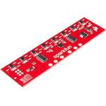
Description。The SparkFun Line Follower Array is a long board consisting of eight IR sensors that have been configured to read as digital bits! We have designed the SparkFun Line Follower Arrays to follow a dark line of about 3/4 inch width or smaller(spray paint or electrical tape)on a light background. Each array features visible LEDs that point upward when the board is attached(properly)so you can see what the robot sees, brightness control right on the board, and an I2C interface for reading and power control. Here at SparkFun, the RedBot Shadow Chassis was used as a test platform but really this was designed as an add-on for almost any bot.。The line follower functions by taking an 8-bit reading of reflectance for use with following lines or reading dark/light patterns and can see from about 1/4 to 3/4 inches away. The IR brightness control and indicator can be adjusted with the on-board potentiometer and is capable of showing you the strength of the IR LEDs. Illumination can be turned on and off with software to conserve power, or left on all the time for faster readings. The SparkFun Line Follower Array requires 5V of power with a supply current range of 25-185mA with strobing disabled and 16-160mA with it enabled. Additionally we have added six mounting holes to the line follower with the two inner holes designed to fit our Shadow Chassis while the other four are general purpose.。Note:As you know our Sun emits quite a bit of infrared light, making the SparkFun Line Follower Array much less effective in direct sunlight. Plan your projects accordingly!。Features。8 sensor eyes(QRE1113, like in our line sensor breakout)。I2C interface。Adjust IR brightness on the fly with a knob。Switch IR on and off with software。Switch visual indicators on and off with software。Invert dark/light sight with software。Based on the SX1509 I/O expander
アズワン品番67-0426-55
1個
¥13,980
税込¥15,378
欠品中

Description。The PicoBuck LED Driver is an economical and easy to use driver that will allow you to control and blend three different LEDs on three different channels. By default, each channel is driven at 330mA; that current can be reduced by either presenting an analog voltage or a PWM signal to the board. Version 12 of the board adds a solderable jumper that can be closed to increase the maximum current to 660mA. The new voltage regulator also increased the voltage rating on the various components on the board, allowing it to be used up to the full 36V rating of the AL8805 part.。Three signal inputs are provided for dimming control. You can use the PWM signal from an Arduino or your favorite microcontroller to dim each channel individually, or you can tie them all to the same PWM for simultaneous dimming. Dimming can be done by an analog voltage(20%-100% of max current by varying voltage from .5V-2.5V)or by PWM(so long as PWM minimum voltage is less than .4V and maximum voltage is more than 2.4V)for a full 0-100% range. A small jumper is provided for each channel to allow you to increase the drive strength from 330mA to 660mA. Two mounting holes for 4-40 or M3 screws are provided on either side of the board. They are perforated so they can be easily snapped off with a pair of pliers, if a smaller footprint is desired.。Note:。If you're going to use screw terminals, this board uses two different sizes. Check the related products for both sizes you'll need.。Note:。The PicoBuck LED Driver was made in collaboration with Ethan Zonca. A portion of each sale is given back to him.
アズワン品番67-0420-83
1個
¥5,298
税込¥5,828
33日以内出荷

Description。The SCD30 from Sensirion is a high quality Nondispersive Infrared(NDIR)based CO2 sensor capable of detecting 400 to 10000ppm with an accuracy of ±(30ppm+3%). In order to improve accuracy the SCD30 has temperature and humidity sensing built-in, as well as commands to set the current altitude. For additional accuracy the SCD30 also accepts ambient pressure readings!。We've written an Arduino library to make reading the CO2, humidity, and temperature very easy. It can be downloaded through the Arduino Library manager:search for 'SparkFun SCD30' or it can be found in the。Documents。tab above.。The SCD30 Humidity and Temperature Sensor can also be automatically detected, scanned, configured, and logged using the OpenLog Artemis datalogger system. No programming, soldering, or setup required!。Note:The SCD30 has an automatic self-calibration routine. Sensirion recommends 7 days of continuous readings with at least 1 hour a day of 'fresh air' for self-calibration to complete.。Features。Power supply voltage:3.3V - 5.5V。NDIR CO2 sensor technology。Integrated temperature and humidity sensor。Best performance-to-price ratio。Dual-channel detection for superior stability。Small form factor:35 mm×23 mm×7 mm。Measurement range:400 ppm - 10.000 ppm。Accuracy:±(30 ppm + 3%)。Current consumption:19 mA @ 1 meas. per 2 s.。Energy consumption:120 mJ @ 1 measurement。Fully calibrated and linearized。Digital interface UART or I2C
アズワン品番67-0430-35
1個
¥23,980
税込¥26,378
33日以内出荷

。Description。The SparkFun Qwiic TMP117 breakout is a high precision temperature sensor equipped with an I2C interface. It outputs temperature readings with high precision of ±0.1℃ across the temperature range of -20℃ to +50℃s with no calibration and a maximum range from -55℃ to 150℃. The SparkFun High Precision Temperature Sensor also has a very low power consumption rate which minimizes the impact of self-heating on measurement accuracy. Utilizing our handy Qwiic system, no soldering is required to connect it to the rest of your system. However, we still have broken out 0.1"-spaced pins in case you prefer to use a breadboard.。The SparkFun High Precision Temperature Sensor also includes programmable temperature limits, and digital offset for system correction. While the TMP102 is capable of reading temperatures to a resolution of 0.0625℃ and is accurate up to 0.5℃, the on-board TMP117 is not only more precise but has a 16-bit resolution of 0.0078℃!。To make this breakout even easier to use, we've written an Arduino library to help you get started "Qwiic-ly." Check the Documents tab above for more information.。The SparkFun Qwiic Connect System is an ecosystem of I2C sensors, actuators, shields and cables that make prototyping faster and less prone to error. All Qwiic-enabled boards use a common 1mm pitch, 4-pin JST connector. This reduces the amount of required PCB space, and polarized connections mean you can't hook it up wrong.。The TMP117 High Precision Temperature Sensor can also be automatically detected, scanned, configured, and logged using the OpenLog Artemis datalogger system. No programming, soldering, or setup required!。Need a custom board? This component can be found in SparkFun's A La Carte board builder. You can have a custom design fabricated with this component - and your choice of hundreds of other sensors, actuators and wireless devices - delivered to you in just a few weeks.。Get Started with the SparkFun High Precision TMP117 Hookup Guide。Features。Uses I2C interface(Qwiic-enabled)。Four selectable addresses。0x48(default), 0x49, 0x4A, 0x4B。16-bit resolution, 0.0078℃。High accuracy, digital temperature sensor。±0.1℃(max)from ?20℃ to 50℃。±0.15℃(max)from ?40℃ to 70℃。±0.2℃(max)from ?40℃ to 100℃。±0.25℃(max)from ?55℃ to 125℃。±0.3℃(max)from ?55℃ to 150℃。Operating temperature range。-55℃ to +150℃。Operating voltage range。1.8V to 5.5V。Typically 3.3V if using the Qwiic cable。Low power consumption。3.5μA(1-Hz conversion cycle)。150nA(shutdown current)。Programmable operating modes。Continuous, one-shot, and shutdown。Programmable temperature alert limits。Selectable averaging for reduced noise。Digital offset for system correction。NIST traceability。。Documents。Schematic。Eagle Files。Board Dimensions。Hookup Guide。Datasheet(TMP117)。Arduino Library。GitHub Hardware Repo
アズワン品番67-0427-10
1個
¥4,898
税込¥5,388
33日以内出荷

Description。Please note, these machines are built to order have an estimated lead time of 4 business days before shipping。This is the Shapeoko 4 XL, nearly double the cutting area of the Shapeoko 4 Standard! The Shapeoko is a 3-axis CNC Machine kit that allows you to create your 2D and 3D designs out of non-ferrous metals, hardwoods, and plastics. The Shapeoko 4 XL is designed to be affordable enough for any shop and powerful enough to do real work. Don't let the size intimidate you! This is an entry-level CNC machine designed for hobbyists, artists, and fabricators!。Each Shapeoko 4 XL has a cutting area of 838.2mm(X)x 444.5 mm(Y)x 101.6mm(Z)(33"×17.5"×4")and an overall footprint of 1270mm(X)x 609.6mm(Y)x 482.6mm(Z)(50"×24"×19"). The power cable included in this kit is designed for the United States National Plug Standard. Don't forget you can put whatever you want on the adapter ring(as long as it fits), whether that's a laser, 3D print extrusion head, or a marker. Get creative!。Upgrades from the Shapeoko 3 include:New, more rigid v-wheel design。15mm belts。Inductive homing switches。New electronics。Integrated t-slot Hybrid Table(OPTIONAL)。Fully-supported Y extrusions。Leadscrew-driven Z-axis。New, more rigid 65mm router mount。Sweepy 65mm V2 dust boot。Note:This item is non-returnable. If this item arrives damaged or is not functioning properly, please do not hesitate to contact us to see if further actions may be taken.。Not Compatible with the Shapeoko 4:Expansion Packs。T-Track Clamp Kits。Z-Plus。Proximity Switch Kit。Maintenance Kit。Shapeoko 3 Bit Setter。HDZ 4.0。。Features。Footprint:1270mm×609.6mm×482.6mm(50"×24"×19")。Cutting Area:838.2mm×444.5mm×101.6mm(33"×17.5"×4")。Weight 137lbs.。Operating System:Mac(OSX 10.14 or higher)or PC(Windows 8.1 or 10, Intel or AMD)
アズワン品番67-0428-90
1個
¥799,800
税込¥879,780
33日以内出荷

Description。The MCP9600 Breakout is a high accuracy Thermocouple Amplifier equipped with an I2C interface, accessed over our Qwiic system. Inside the chip are two temperature sensors, one for the thermocouple itself(the hot junction)and one for the chip itself(the cold junction). As a result, the MCP9600 can read both the ambient temperature and the temperature of whatever you're trying to measure! The MCP9600 can do both with a resolution of 0.0625℃, and an accuracy of ±1.5℃(worst-case). The MCP9600 Thermocouple Amplifier is one of our many Qwiic compatible boards! Simply plug and go. No soldering, no figuring out which is SDA or SCL, and no voltage regulation or translation required!。This version of the board comes equipped with screw terminals to allow for your own Thermocouple's wiring to be hooked up with the turn of a screw. This makes it perfect for a variety of applications, from measuring the temperature of your Crock-Pot to making sure your backyard induction furnace is up to temperature.。In addition, the MCP9600 has four on-board temperature alerts that you can configure! Instead of constantly polling the sensor over I2C, you can set a temperature limit to trigger an interrupt when the temperature reaches a certain value. This frees up your microcontroller and your I2C bus to do more important things. It's also possible to put the MCP9600 into alternate operation modes in order to save power. The sensor supports a burst mode, where it will take a specified number of samples, return the results, and then go to sleep. This low-power mode makes the MCP9600 perfect for portable applications!。We've written an Arduino library to help you get started quickly. You can download the library through the Arduino library manager by searching 'SparkFun MCP9600' or you can get the GitHub repo as a .zip file and install the library from there.。The SparkFun Qwiic Connect System is an ecosystem of I2C sensors, actuators, shields and cables that make prototyping faster and less prone to error. All Qwiic-enabled boards use a common 1mm pitch, 4-pin JST connector. This reduces the amount of required PCB space, and polarized connections mean you can't hook it up wrong.。Get Started with the Qwiic Thermocouple Amplifier。Features。Temperature Range of -200℃ to 1350℃。Four Onboard Temperature Alerts。Resolution of 0.0625℃。Screw Terminal Connector。ADDR Jumper for variable I2C Addresses(default address of 0x60)。2x Qwiic Connectors
アズワン品番67-0427-15
1個
¥8,998
税込¥9,898
欠品中

。Description。Do you want to replace a slider or a button on your art project or science experiment with a more interesting interface? This Capacitive Touch Slider is a "Qwiic" and easy way to add capacitive touch to your next project. With the board's built in touch pads, you can immediately start playing with the touch capabilities as three unique touch inputs or as a slider. You can also enable a touch input to act as a power button, customize the sensitivity for your own touch pads, and play with the interrupt alert LED. Utilizing our Qwiic system, no soldering is required to connect it to the rest of your system. However, we have broken out 0.1"-spaced pins in case you prefer to use a breadboard or create your own touch pads.。On the front of the board, there is an arrow shape which contains three separate capacitive touch pads. We also broke out the capacitive touch sensor lines as plated through-holes on the top of the board. You can use these pins to connect to your own capacitive touch pads. The CS1 pin connects to the left pad, the CS2 pin connects to the middle pad, and the CS3 pin connects to the right pad.。NOTE:The I2C address of the CAP1203 is 0x28 and is hardware defined. A multiplexer/Mux is required to communicate to multiple CAP1203 sensors on a single bus. If you need to use more than one CAP1203 sensor consider using the Qwiic Mux Breakout.。The SparkFun Qwiic connect system is an ecosystem of I2C sensors, actuators, shields and cables that make prototyping faster and less prone to error. All Qwiic-enabled boards use a common 1mm pitch, 4-pin JST connector. This reduces the amount of required PCB space, and polarized connections mean you can't hook it up wrong.。Get Started with the SparkFun Capacitive Touch Slider Guide。Features。Capacitive Touch。3 unique capacitive touch inputs。Features。Emulated slider。Power button setting。Programmable sensitivity。Automatic recalibration。I2C Address:0x28。Qwiic Enabled。Operating Range。Supply Voltage:3.3V - 5V
アズワン品番67-0427-06
1個
¥2,498
税込¥2,748
33日以内出荷

Description。The SparkFun LSM6DSO 6 Degrees of Freedom Breakout is an accelerometer and gyroscope sensor with a giant 9kB FIFO buffer and embedded processing interrupt functions. Due to the capabilities and low cost of the LSM6DSO we've created this small breakout board just for you! Each LSM6DSO breakout has been designed to be super-flexible and can be configured specifically for many applications. With the LSM6DSO breakout you will be able to detect shocks, tilt, motion, taps, count steps, and even read the temperature!。The LSM6DSO from STMicroelectronics is capable of reading accelerometer and gyroscope data up to 6.66kHz for more accurate movement sensing. As stated before this breakout also has the ability to buffer up to 9kB of data between reads, host other sensors, and drive interrupt pins all thanks to the LSM6DSO's built-in FIFO.。Utilizing our handy Qwiic system, no soldering is required to connect it to the rest of your system. However, we still have broken out 0.1"-spaced pins in case you prefer to use a breadboard. Each pin has been broken out on the LSM6DSO, with one side of the board featuring power, I2C, and SPI functionality while the other side sporting pins that control auxiliary functionality and interrupt outputs. Please keep in mind that the LSM6DSO is a 3.3V device so supplying voltages greater than ~3.6V can permanently damage the IC. A logic level shifter is required for any development platform operating at 5V.。The SparkFun Qwiic Connect System is an ecosystem of I2C sensors, actuators, shields and cables that make prototyping faster and less prone to error. All Qwiic-enabled boards use a common 1mm pitch, 4-pin JST connector. This reduces the amount of required PCB space, and polarized connections mean you can't hook it up wrong.。Get Started With the SparkFun LSM6DSO Qwiic 6DoF Guide。Features。2x Qwiic connectors。I2C Address。0x6B(default)。, 0x6A。Accelerometer measurement range。±2/±4/±8/±16 g full scale。Gyro measurement range。±125/±250/±500/±1000/±2000 dps full scale。Embedded temperature sensor。16-bit resolution。Operating voltage range。1.71V to 3.6V。Typically。3.3V。if using the Qwiic cable。Power consumption @ 1.8V。0.55 mA in combo high-performance mode。0.265 mA in combo low-power mode。"Always on" experience with low power consumption for both accelerometer and gyroscope。I2C/SPI serial interface with main processor data synchronization feature。Smart FIFO up to 9 kbyte based on features set。Operating temperature range。-40℃ to +85℃
アズワン品番67-0427-54
1個
¥5,198
税込¥5,718
欠品中

。Description。The SparkFun Inventor's Kit(SIK)for Arduino Uno is a great way to get started with programming and hardware interaction with the Arduino programming language. The SIK includes everything you need to complete five overarching projects consisting of 16 interconnected circuits that teach everything from blinking an LED to reading sensors. The culminating project is your very own autonomous robot! No previous programming or electronics experience is required to use this kit.。The online guide contains step-by-step instructions with circuit diagrams and hookup tables for building each project and circuit with the included parts. Full example code is provided, new concepts and components are explained at point of use, and troubleshooting tips offer assistance if something goes wrong.。The kit does not require any soldering and is recommended for beginners ages 10 and up who are looking for an Arduino starter kit. For SIK version 4.1 we took an entirely different approach to teaching embedded electronics. In previous versions of the SIK, each circuit focused on introducing a new piece of technology. With SIK v4.1, components are introduced in the context of the circuit you are building, and each circuit builds upon the last, leading up to a project that incorporates all of the components and concepts introduced throughout the guide. With new parts and a completely new strategy, even if you've used the SIK before, you're in for a brand-new experience!。This version of the SIK replaces the SparkFun RedBoard Qwiic with the Arduino Uno(SMD version)and comes without the SIK guidebook and carrying case. With these components being swapped and removed, we were able to reduce the overall size and weight of the kit, making shipping cheaper and easier for anyone ordering internationally.。Note:As stated above, this SIK does NOT include a carrying case or print guidebook.。Get Started With the SparkFun Inventor's Kit v4.1 Experiment Guide。Examples。Project 1:Light。Circuit 1A:Blinking an LED。Circuit 1B:Potentiometer。Circuit 1C:Photoresistor。Circuit 1D:RGB Night-Light。Project 2:Sound。Circuit 2A:Buzzer。Circuit 2B:Digital Trumpet。Circuit 2C:"Simon Says" Game。Project 3:Motion。Circuit 3A:Servo Motors。Circuit 3B:Distance Sensor。Circuit 3C:Motion Alarm。Project 4:Display。Circuit 4A:LCD "Hello, World!"。Circuit 4B:Temperature Sensor。Circuit 4C:"DIY Who Am I?" Game。Project 5:Robot。Circuit 5A:Motor Basics。Circuit 5B:Remote-Controlled Robot。Circuit 5C:Autonomous Robot
アズワン品番67-0424-34
1個
¥34,980
税込¥38,478
33日以内出荷

Description。The FLIR Lepton(R)2.5 - Thermal Imaging Module is a radiometric-capable long wave infrared(LWIR)camera solution that is smaller than a dime, fits inside a smartphone, and is less expensive than traditional IR cameras. With a focal plane array of 80x60 active pixels, this Lepton easily integrates into native mobile-devices and other electronics as an IR sensor or thermal image sensor. The radiometric Lepton captures accurate, calibrated, and non-contact temperature data in every pixel.。For large quantities:We currently have a limit of one per customer order on the FLIR Lepton 2.5 module due to supply chain issues as a result of COVID-19. If you need to place a distributor order please contact your sales rep and they will assist you. For bulk order for this module please visit our Volume Pricing Page for inquiries of stock. At this time, we cannot guarantee orders for this module but we will do what we can to work with you in fulfilling your request.。Features。Effective Frame Rate:8.6 Hz(commercial application exportable)。Input Clock:25-MHz nominal, CMOS IO Voltage Levels。Output Format:User-selectable 14-bit, 8-bit(AGC applied), or 24-bit RGB(AGC and colorization applied)。Pixel Size:17 μm。Radiometric Accuracy:High gain:Greater of +/- 5℃ or 5%(typical)Low gain:Greater of +/- 10℃ or 10%(typical)。Scene Dynamic Range:-10-140 ℃(high gain); up to 450℃(low gain)typical。Spectral Range:Longwave infrared, 8 μm to 14 μm。Temperature Compensation:Automatic. Output image independent of camera temperature.。Thermal Sensitivity:<50 mK(0.050° C)。Video Data Interface:Video over SPI。Control Port:CCI(I2C-like), CMOS IO Voltage Levels。Package Dimensions - Socket Version(w×l×h):11.8×12.7×7.2 mm。Mechanical Interface:32-pin socket interface to standard Molex(R)socket。Non-Operating Temperature Range:-40 ℃ to +80 ℃。Optimum Temperature Range:-10℃ to +80℃。Shock:1500 G @ 0.4 ms。Array format:80×60, progressive scan。FOV - Diagonal:63.5°。FOV - Horizontal:50°(nominal)。Image Optimization:Factory configured and fully automated。Non-Uniformity Correction(NUC):Automatic with shutter。Sensor Technology:Uncooled VOx microbolometer。Solar protection:Integral。Input Supply Voltage:2.8 V, 1.2 V, 2.5 V to 3.1 V IO。Power Dissipation:150 mW(operating), 650 mW(during shutter event), 4 mW(standby)
アズワン品番67-0427-21
1個
¥68,980
税込¥75,878
33日以内出荷

Description。The SparkFun Pulse Oximeter and Heart Rate Sensor is an I2C based biometric sensor, utilizing two chips from Maxim Integrated:the MAX32664 Biometric Sensor Hub and the MAX30101 Pulse Oximetry and Heart Rate Module. While the latter does all the sensing, the former is an incredibly small and fast Cortex M4 processor that handles all of the algorithmic calculations, digital filtering, pressure/position compensation, advanced R-wave detection, and automatic gain control. We've provided a Qwiic connector to easily connect to the I2C data lines but you will also need to connect to two additional lines. This board is very small, measuring at 1in×0.5in(25.4mm×12.7mm), which means it will fit nicely on your finger without all the bulk.。The MAX30101 does all the sensing by utilizing its internal LEDs to bounce light off the arteries and arterioles in your finger's subcutaneous layer and sensing how much light is absorbed with its photodetectors. This is known as photoplethysmography. This data is passed onto and analyzed by the MAX32664 which applies its algorithms to determine heart rate and blood oxygen saturation(SpO2). SpO2 results are reported as the percentage of hemoglobin that is saturated with oxygen. It also provides useful information such as the sensor's confidence in its reporting as well as a handy finger detection data point. To get the most out of the sensor we've written an Arduino Library to make it easy to adjust all the possible configurations.。The SparkFun Qwiic connect system is an ecosystem of I2C sensors, actuators, shields and cables that make prototyping faster and less prone to error. All Qwiic-enabled boards use a common 1mm pitch, 4-pin JST connector. This reduces the amount of required PCB space, and polarized connections mean you can't hook it up wrong.。Get Started with the Pulse Oximeter and Heart Rate Monitor Hookup Guide。Features。SparkFun Pulse Oximeter and Heart Rate Sensor。MAX30101 and MAX32664 sensor and sensor hub。Qwiic connectors for power and I2C interface。I2C Address:0x55。MAX30101 - Pulse Oximeter and Heart-Rate Sensor。Heart-Rate Monitor and Pulse Oximeter Sensor in LED Reflective Solution。Integrated Cover Glass for Optimal, Robust Performance。Ultra-Low Power Operation for Mobile Devices。Fast Data Output Capability。Robust Motion Artifact Resilience。MAX32664 - Ultra-Low Power Biometric Sensor Hub。Biometric Sensor Hub Solution。Finger-Based Algorithms Measure Pulse Heart Rate and Pulse Blood Oxygenation Saturation(SpO2)。Both Raw and processed data are available。Basic Peripheral mix optimizes size and performance
アズワン品番67-0426-96
1個
¥13,980
税込¥15,378
33日以内出荷
関連キーワード
