カテゴリ
- 学童・教育用品(4)
絞り込み
ブランド
- SPARKFUN
- MICROCHIP(4)
- アイロジック(1)
「attiny84」の検索結果
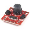
 SparkFun Servo TriggerSPARKFUN
¥5,598税込¥6,158
1個
5日以内出荷
Servo Triggerは、小型ロボットなどのRCサーボモータの制御を簡単に行えるボードです。外部スイッチまたはロジック信号のサーボトリガにより、接続されたサーボモータの位置Aから位置Bに移動するように指示することができます。サーボトリガを使用するには、オンボードの半固定抵抗を使用してスタート/ストップ位置とトランジション時間を調整します。制御にはATTiny84マイクロコントローラを使用して、サーボ制御プログラムを実行しています。オンボードの各サーボトリガには、3つの半固定抵抗があります。Aはスイッチがオープンのときサーボが入る位置を設定し、Bはスイッチがクローズしたときにサーボが移動する位置を設定し、TはAからBに戻ってくるのにかかる時間を設定します。2つの動作モードがあり、裏面のジャンパ(SJ1)で切り替えられます。デフォルトはスイッチ開でA、スイッチ閉でBになるBistableモードで、SJ1をショートするとスイッチを押すたびにAB、ABを繰り返すOne shotモードになります。主な仕様コントローラ:ATTiny84推奨電圧:5V最大電圧:5.5V消費電流:5mA3つの制御設定A:スイッチがオープン時のサーボ位置の設定B:スイッチがクローズ時のサーボ位置の設定C:AからB、BからAに戻るのにかかる時間の設定入力極性を設定可能応答モードを設定可能アナログサーボと互換性があるISPヘッダピンを再プログラムに使用可能
アズワン品番63-3035-84
 SparkFun Qwiic PIR - 170uA EKMC4607112KSPARKFUN
¥5,498税込¥6,048
1個
33日以内出荷
DescriptionPassive Infrared(PIR)sensors are great for detecting motion in a small area around the sensor. The 170μA SparkFun EKMC4607112K Qwiic PIR uses an EKM-series PIR sensor from Panasonic(R)paired with an ATTiny84 to interact with it using I2C
アズワン品番67-0427-45
 SparkFun Qwiic Dual Solid State RelaySPARKFUN
¥39,980税込¥43,978
1個
33日以内出荷
DescriptionThe SparkFun Qwiic Dual Solid State Relay is a power delivery board that allows users to switch two AC loads from a low power microcontroller using the SparkFun Qwiic connect system. The board features two 25A/250VAC solid state relays that utilize the Zero Cross Trigger method so you can toggle two loads on a 60Hz AC carrier signal on and off up to 120 times per second!An ATTiny84 acts as the "brain" of the SparkFun Qwiic Dual Solid Relay to accept I2C commands to toggle the two relays as well as a few other special commands. The I2C address of the ATtiny84A is software configurable so, if you have a seriously big power project in mind, you could daisy chain over 100 Qwiic Dual Solid State Relays.Messing with such high voltage is dangerous! We've included many safety precautions onto the PCB including ground isolation between the relay and other circuitry and a milled out area isolating each side of AC. However, with all the safety precautions included with the SparkFun Qwiic Dual Solid State Relay, this is still a power accessory for users who are experienced around, and knowledgeable about high AC voltage. If you're not comfortable with handling AC voltage in this way, you may want to check out the IoT Power Relay instead.Note:The relays are rated for a max of 25A with forced air cooling. If you do not have forced air cooling, 10A max through the relays is recommended.The SparkFun Qwiic connect system is an ecosystem of I2C sensors, actuators, shields and cables that make prototyping faster and less prone to error. All Qwiic-enabled boards use a common 1mm pitch, 4-pin JST connector. This reduces the amount of required PCB space, and polarized connections mean you can't hook it up wrong.Get Started with the SparkFun Qwiic Dual Solid State Relay GuideFeaturesOperating Voltage:2.5-3.6V(3.3V recommended)I2C Address:0x0A(Default)0x0B(Alternate via jumper select)Load Voltage Range:12-280VACMax Current(Through Relay):25A(240VAC with forced air cooling)Zero Cross TriggerNormally Open Circuit Only2x Qwiic Connector
アズワン品番67-0421-58
 SparkFun Servo Trigger - Continuous RotationSPARKFUN
¥4,898税込¥5,388
1個
33日以内出荷
DescriptionThe SparkFun Continuous Rotation(CR)Servo Trigger is a small robotics board that simplifies the control of hobby RC servo motors. When an external switch or logic signal changes state, the CR Servo Trigger is able to tell an attached servo motor to move from position A to position B. To use the CR Servo Trigger, you simply connect a hobby servo and a switch, then use the on-board potentiometers to adjust the start/stop positions and the transition time. You can use a hobby servo in your projects without having to do any programming!When we introduced the original Servo Trigger, we mentioned that it could be reprogrammed to be more useful with continuous rotation servo motors. But reprogramming the firmware is somewhat tedious, and users asked for a Servo Trigger preprogrammed with the continuous rotation logic. With this little board you will be provided an easy way to deploy continuous rotation servos into your projects!The heart of the CR Servo Trigger is an Atmel ATtiny84 microcontroller, running a small program that implements the servo control features designed for continuous rotation servos. On board each of these CR Servo Triggers you will find three potentiometers:"A" sets the position the servo sits in while the switch is open, "B" sets the position the servo moves to when the switch is closed, and "T" sets the time it takes to get from A to B and back.Compared with a servo motor, the CR Servo Trigger board draws very little current, roughly 5mA at 5V. Be sure to note that if you're using the CR Servo Trigger to control your motor, the absolute maximum supply voltage that should be applied is 5.5 VDC. Additionally, the SparkFun CR Servo Trigger is designed to make it easy to daisy chain boards - you can simply connect the VCC and GND pads on adjacent boards to each other.Note:This idea originally came from our friend in the Oakland area, CTP. If you see him, please give him a high-five for us.SparkFun CR Servo Trigger Hookup GuideFeaturesRecommended Voltage:5VDCMax Voltage:5.5VDCCurrent Draw:5mAControl Continuous Rotation ServosThree Control SettingsA - sets the position the servo sits in while the switch is openB - sets the position the servo moves to when the switch is closedC - sets the time it takes to get from A to B and backEasy Control with PotentiometersConfigurable Input PolarityConfigurable Response ModeCompatible with Analog ServosISP Header Pins Available for Reprogram
アズワン品番67-0429-21