カテゴリ
- 学童・教育用品(43)
- 制御機器(5)
- 電気材料(1)
絞り込み
ブランド
- SPARKFUN
- KEMET(244)
- TE Connectivity Japan(旧:TYCOELECTRONICS(タイコエレクトロニクス))(212)
- 三菱ふそう(98)
- RS PRO(89)
- piaggio(ピアッジオグループ)(75)
- HY Electronic Corp(54)
- KOA(53)
- イトーキ(36)
- ホンダ(33)
- CCTYベアリングジャパン(31)
- シュナイダーエレクトリック(31)
- bitstrong(27)
- 積水樹脂(26)
- KTM(24)
- CCT(21)
- SKF(日本エスケイエフ)(18)
- フエニックス・コンタクト(16)
- MV AGUSTA(15)
- ブランドをもっと見る
「cct」の検索結果
特価
 ArduinoMega 2560 R3SPARKFUN
¥18,980税込¥20,878
1個
33日以内出荷
DescriptionArduino is an open-source physical computing platform based on a simple i/o board and a development environment that implements the Processing/Wiring language. Arduino can be used to develop stand-alone interactive objects or can be connected to software on your computer(e.g. Flash, Processing, MaxMSP). The open-source IDE can be downloaded for free(currently for Mac OS X, Windows, and Linux).The Arduino Mega is a microcontroller board based on the ATmega2560. It has 54 digital input/output pins(of which 14 can be used as PWM outputs), 16 analog inputs, 4 UARTs(hardware serial ports), a 16 MHz crystal oscillator, a USB connection, a power jack, an ICSP header, and a reset button. It contains everything needed to support the microcontroller; simply connect it to a computer with a USB cable or power it with a AC-to-DC adapter or battery to get started.Never fear for accidental electrical discharge, either since since the Mega also includes a plastic base plate to protect it!The Mega 2560 R3 also adds SDA and SCL pins next to the AREF.In addition, there are two new pins placed near the RESET pin. One is the IOREF that allow the shields to adapt to the voltage provided from the board.The other is a not connected and is reserved for future purposes.The Mega 2560 R3 works with all existing shields but can adapt to new shields which use these additional pins.Not sure which Arduino or Arduino-compatible board is right for you? Check out our Arduino Buying Guide!FeaturesATmega2560 microcontrollerInput voltage - 7-12V54 Digital I/O Pins(14 PWM outputs)16 Analog Inputs256k Flash Memory16Mhz Clock Speed
アズワン品番67-0349-13
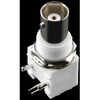
 BNC Connector - Right AngleSPARKFUN
¥869税込¥956
1個
33日以内出荷
仕様●カテゴリ:BNC型コネクタ●プラグ/ジャック:ジャック●形状:ライトアングル型●コネクタタイプ:基板アズワン品番67-0454-60
 USB Female Type C ConnectorSPARKFUN
¥1,098税込¥1,208
1個
33日以内出荷
DescriptionUSB-C is quickly becoming more and more prominent in the maker community because, let's be honest, who likes trying three times to insert USB into a port? This is a 16-pin, female, USB Type C connector that is commonly found in smart phones, laptops, and other newer electronics. Each USB-C connector will require PTH soldering to secure it to your board and SMD soldering to connect each of the 16 control pins.If you are looking for an easier way to hook up a USB-C connector to your project, we do offer a breakout with 0.1" spaced, breadboard friendly pins.
アズワン品番67-0421-35
 SparkFun Qwiic Thermocouple Amplifier - MCP9600 PCC ConnectorSPARKFUN
¥17,980税込¥19,778
1個
欠品中
DescriptionThe MCP9600 Breakout is a high accuracy Thermocouple Amplifier equipped with an I2C interface, accessed over our Qwiic system. Inside the chip are two temperature sensors, one for the thermocouple itself(the hot junction)and one for the chi
アズワン品番67-0427-14
 RJ11 6-Pin ConnectorSPARKFUN
¥599税込¥659
1個
33日以内出荷
Through-hole RJ11 socket with PCB mounting posts. 6-pin connection - housing accepts common telephone connectors/wiring.
仕様●ピン数:6極●プラグ/ジャック:ジャックアズワン品番67-0454-06
 SparkFun Triple Axis Accelerometer Breakout - KX132 QwiicSPARKFUN
¥4,498税込¥4,948
1個
33日以内出荷
DescriptionThis SparkFun Triple-Axis Accelerometer Breakout is a simple Qwiic breakout for the KX132 digital accelerometer from Kionix. The KX132 is a low-power, 16-bit resolution three-axis accelerometer with four user-selectable acceleration measur
アズワン品番67-0427-52
 FPC Camera Connector - 24-Pin, 0.5mm Bottom-ContactSPARKFUN
¥369税込¥406
1個
33日以内出荷
DescriptionAmphenol FCI FFC/FPC Flexible Circuit Connectors are a broad range of innovative connector solutions to terminate FFC/FPC. This 24-Pin FPC connector has a 0.5mm pitch and comes with a bottom contact in a right angle orientation and a surfac
アズワン品番67-0421-51
 Rotary Potentiometer - 100k Ohm, Linear Panel MountSPARKFUN
¥1,098税込¥1,208
1個
欠品中
DescriptionAn adjustable potentiometer can open up many interesting user interfaces. With this rotary potentiometer just turn the dial and the resistance changes. This potentiometer from Bourns has a 1/4" metal knurled shaft diameter, solder lug terminals, no detents, and has a 100K linear taper.Connect VCC to an outer pin, GND to the other, and the center pin will have a voltage that varies from 0 to VCC depending on the rotation of the pot. Hook the center pin to an ADC on a microcontroller and get a variable input from the user!
アズワン品番67-0421-09
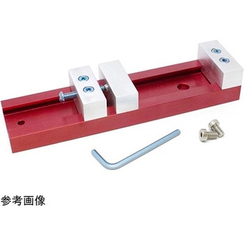 Nomad Low Profile ViseSPARKFUN
¥42,980税込¥47,278
1個
33日以内出荷
DescriptionThis Low Profile Vise provides you with a compact workholding accessory for the Nomad 883 Pro. Each one of these vises are made from scratch, in-house at Carbide 3D, and includes everything you need to attach it to your Nomad. With the Low Profile Vise you will be able to create miniature and small silhouette milling projects.The Low Profile Vise has a maximum clamping width of 6.5in(~165mm)and is only 8in(~203mm)long and 2in(~50mm)wide. It should go without saying that this vise will easily provide you the ability to mill and fabricate more unique objects!
アズワン品番67-0428-33
 Amphenol FCI Clincher Connector Position, Female) COMシリーズSPARKFUN
¥649税込¥714
1個
欠品中
DescriptionThough the Clincher connector can be used with FFCs, we also like to use them with our FlexiForce sensors and other flex/force sensors found in theRecommended Productssection below.Note:Please be aware that we will not be able to accept returns on this connector if it has been closed. Sorry for any inconvenience this may cause.
アズワン品番67-0420-96
 Amphenol FCI Clincher Connector Position, Female) COMシリーズSPARKFUN
¥999税込¥1,099
1個
欠品中
DescriptionThough the Clincher connector can be used with FFCs, we also like to use them with our FlexiForce sensors and other flex/force sensors found in theRecommended Productssection below.Note:Please be aware that we will not be able to accept returns on this connector if it has been closed. Sorry for any inconvenience this may cause.
アズワン品番67-0420-95
 SparkFun Multiplexer Breakout - 8 Channel 74HC4051SPARKFUN
¥999税込¥1,099
1個
33日以内出荷
DescriptionThe SparkFun Multiplexer Breakout provides access to all pins and features of the 74HC4051, an 8-channel analog multiplexer/demultiplexer. The 74HC4051 allows you to turn four I/O pins into eight multifunctional, individually selectable signals, which can be used to do everything from driving eight LEDs to monitoring eight potentiometers.The 74HC4051 can function as either a multiplexer or a demultiplexer, and it features eight channels of selectable inputs/outputs. The routing of common signal to independent I/O is set by digitally controlling three select lines, which can be set either high or low into one of eight binary combinations.One half of the board breaks out the control signals(E, S0-S2)and common input/output(Z). The other side provides access to all eight independent I/O's(Y0-Y7). Both sides include supply and ground connections(VCC, VEE, GND).Get Started with the 74HC4051 Breakout GuideFeaturesSwitches analog or digital signals8 channels controlled by 3 select inputsWide voltage supply range:2 -- 10VBipolar supply support(e.g., ±5V)Optional enable inputBreadboard compatible breakout
アズワン品番67-0419-95
 SparkFun Qwiic Scale - NAU7802SPARKFUN
¥5,698税込¥6,268
1個
33日以内出荷
DescriptionThe SparkFun Qwiic Scale is a small breakout board for the NAU7802 that allows you to easily read load cells to accurately measure the weight of an object. By connecting the board to your microcontroller you will be able to read the change
アズワン品番67-0426-97
 SparkFun 2D Barcode Scanner BreakoutSPARKFUN
¥20,980税込¥23,078
1個
欠品中
DescriptionThe SparkFun 2D Barcode Scanner Breakout is a nifty little breakout board featuring the DE2120 barcode scanner module from DYScan. The DE2120 reads 20 different barcode symbologies(both 1D and 2D)using a camera coupled with on-board image processing to identify and decode everything from UPC codes to QR codes. The module also features two LEDs:one for illumination and one to project the red line that you're used to seeing from laser-based scanners.This breakout board makes it easy to explore all of the capabilities of the DE2120 without dealing with finicky flat flex cables. The scanner's USB interface is exposed via the on-board USB-C connector. A buzzer and status LED are connected to the module through appropriate drive circuits and a push button tactile switch is provided on the "trigger" pin. When you're ready to incorporate the module into your embedded project, you can leverage the 5 pin header for direct access to the TTL serial pins, power pins, and trigger input.The module can be configured either by using the serial interface or by scanning command barcodes found in the Settings Manual.All keyboard, HID, and serial can be transmitted over the single USB-C connector. The DE2120 has the unique ability to enumerate all three protocols including a CDC serial driver so the device appears as a standard COM port.Get Started with the 2D Barcode Scanner Breakout Hookup GuideFeaturesUSB-C Connector for USB HID Interface and Virtual COM portReads 20 different symbologies1D SymbologiesUPC-AUPC-EEAN-8EAN-13Code 128GS1-128Code 39Code 93Code 11Interleaved 2-of-5Matrix 2-of-5Industrial 2-of-5CodabarMSIGS1 DataBarDatalogic 2-of-52D SymbologiesQR CodeData MatrixPDF 417Micro PDF 417Aztec Code
アズワン品番67-0430-36
 SparkFun Cryptographic Co-Processor Breakout - ATECC608A QwiicSPARKFUN
¥1,498税込¥1,648
1個
33日以内出荷
DescriptionProduct Restrictions:To access certain features of the ATECC608A, users will need to contact Microchip and sign an NDA contract to obtain the complete datasheet. Due to the required NDA - technical support, an Arduino library, and hookup guide are not provided for users on this product.The SparkFun ATECC608A Cryptographic Co-processor Breakout allows you to add strong security to your IoT node, edge device, or embedded system. This includesasymmetricauthentication,symmetricAES-128 encryption/decryption, and much more. As stated above, the ATECC608A has limited Arduino support and the complete datasheet is under NDA with Microchip.This breakout board includes two Qwiic ports for plug and play functionality. Utilizing our handy Qwiic system, no soldering is required to connect it to the rest of your system. However, we still have broken out 0.1"-spaced pins in case you prefer to use a breadboard. The ATECC608A chip is capable of many cryptographic processes, including, but not limited to:Creating and securely storing unique asymmetric key pairs based on Elliptic Curve Cryptography(FIPS186-3).AES-128:Encrypt/Decrypt, Galois Field Multiply for GCMCreating and verifying 64-byte digital signatures(from 32-bytes of message data).Creating a shared secret key on a public channel via Elliptic Curve Diffie-Hellman Algorithm.SHA-256 HMAC Hash including off-chip context save/restoreInternal high quality FIPS random number generator.Embedded in the chip is a 10Kb EEPROM array that can be used for storing keys, certificates, data, consumption logging, and security configurations. Access to the sections of memory can then be restricted and the configuration locked to prevent changes. Each ATECC608A Breakout ships with a guaranteed unique 72-bit serial number and includes several security features to prevent physical attacks on the device itself, or logical attacks on the data transmitted between the device.A summary datasheet for the ATECC608A is available here. The full datasheet is under NDA with Microchip. You will need to contact them for access to the entire datasheet. Meanwhile, the ArduinoATECCX08 Library currently only supports the ATECC608A with SAMD21 Arduino boards.We do have much more support for the ATECC508A version of this chip. Please check out our ATECC508A Hookup Guide and Arduino Library(which includes six examples). This will get you familiar with the basics of elliptic curve cryptography and signing/verifying data with the ATECC508A version of the chip.Note:The I2C address of the ATECC608A is 0x60 and is software-configurable to any address. A multiplexer/Mux is required to communicate to multiple ATECC608A sensors at the default address when on a single bus. If you need to use more than one ATECC608A sensor at the default address, consider using the Qwiic Mux Breakout.Note:The ATECC608A can be only configured once before it isPERMANENTLYlocked. It is advisable that users purchase multiple boards in order to use other configurations and explore the advanced functions of the ATECC608A.Additionally, this boardIScapable of encrypting and decrypting data. However, to access these additional features, you will need to contact Microchip and sign an NDA contract to obtain the complete datasheet.It is recommended that an SparkFun RedBoard Turbo - SAMD21 Development Board is used with this product due to the buffer size required on the I2C bus.The SparkFun Qwiic Connect System is an ecosystem of I2C sensors, actuators, shields and cables that make prototyping faster and less prone to error. All Qwiic-enabled boards use a common 1mm pitch, 4-pin JST connector. This reduces the amount of required PCB space, and polarized connections mean you can't hook it up wrong.FeaturesOperating Voltage:2.0V-5.5V(Default on Qwiic System:3.3V)Active Current Draw(for ATECC608A):16 mASleep Current(for ATECC608A):<150 nAGuaranteed Unique 72-bit Serial Number10 Kb EEPROM Memory for Keys, Certificates, and DataStorage for up to 16 Keys256-bit Key LengthInternal High-Quality FIPS Random Number Generator(RNG)Configurable I2C Address(7-bit):0x60(Default)
アズワン品番67-0423-59
 SparkFun Soil Moisture Sensor with Screw TerminalsSPARKFUN
¥2,198税込¥2,418
1個
33日以内出荷
DescriptionThe SparkFun Soil Moisture Sensor is a simple breakout for measuring the moisture in soil and similar materials. The soil moisture sensor is pretty straightforward to use. The two large, exposed pads function as probes for the sensor, together acting as a variable resistor. The more water that is in the soil means the better the conductivity between the pads will be, resulting in a lower resistance and a higher SIG out. This version of the Soil Moisture Sensor includes a 3-pin screw pin terminal pre-soldered to the board for easy wiring and setup.To get the SparkFun Soil Moisture Sensor functioning, all you will need is to connect the VCC and GND pins to your Arduino-based device(or compatible development board). You will receive a SIG out, which will depend on the amount of water in the soil. One commonly known issue with soil moisture senors is their short lifespan when exposed to a moist environment. To combat this, we've had the PCB coated in gold finishing(ENIG, or Electroless Nickel Immersion Gold).Note:Check the Hookup Guide below for assembly and weatherproofing instructions, as well as a simple example project that you can put together yourself!Get Started with the Soil Moisture Sensor Guide
アズワン品番67-0426-56
 Hologram eUICC SIM CardSPARKFUN
¥1,998税込¥2,198
1個
33日以内出荷
DescriptionThe Hologram eUICC SIM Card is a mix between legacy and new technology when cellular service is needed your project. This eUICC SIM Card enables profile switching capabilities so you can dynamically change the subscriber profile while your chosen devices are in the field, over-the-air. For those looking for IoT cellular service with no intentions on switching cellular carriers, this SIM card is for you.eUICC features are limited to certain modules at this point. This includes the u-blox SARA-R4 module used on our SparkFun LTE CAT M1/NB-IoT Shield - SARA-R4. For these situations, the functionality will be that of a normal SIM with cellular service through Hologram. You won't be able to change carriers.FeaturesTemperature Range:-25C to 85CNano SIM 8.8mm x 12.3mmMinimum 500,000 Read/write cyclesMinimum 25 yrs at 25℃ Data retention
アズワン品番67-0420-79
 USB to TTL Serial Cable 5V VCCSPARKFUN
¥5,198税込¥5,718
1個
欠品中
DescriptionThis is a USB to TTL Serial Cable which allows for a simple way to connect TTL interface devices to USB. The I/O pins of this cable are configured to operate at 3.3V specifically with a Raspberry Pi with each serial pin broken apart. Thanks to its separated pins, this cable is a perfect candidate for powering, connecting, and accessing the login and debug console on an older-version Raspberry Pi.The FTDI cable is designed around an FT232, which is housed in a USB-A connector. The other side of the cable is terminated with a separated 4-pin connector with the following pinout:RX(Yellow), TX(Orange), VCC(5V)(Red), and GND(Black). A link to the FTDI drivers can be found in theDocumentssection above.Note:Please be aware that while the I/O pins in this cableoperate at 3.3V, the VCC pin is 5V. The VCC pin is NOT 3.3V like theI/O pins.
アズワン品番67-0420-67
 SparkFun Line Follower ArraySPARKFUN
¥13,980税込¥15,378
1個
欠品中
DescriptionThe SparkFun Line Follower Array is a long board consisting of eight IR sensors that have been configured to read as digital bits! We have designed the SparkFun Line Follower Arrays to follow a dark line of about 3/4 inch width or smaller(spray paint or electrical tape)on a light background. Each array features visible LEDs that point upward when the board is attached(properly)so you can see what the robot sees, brightness control right on the board, and an I2C interface for reading and power control. Here at SparkFun, the RedBot Shadow Chassis was used as a test platform but really this was designed as an add-on for almost any bot.The line follower functions by taking an 8-bit reading of reflectance for use with following lines or reading dark/light patterns and can see from about 1/4 to 3/4 inches away. The IR brightness control and indicator can be adjusted with the on-board potentiometer and is capable of showing you the strength of the IR LEDs. Illumination can be turned on and off with software to conserve power, or left on all the time for faster readings. The SparkFun Line Follower Array requires 5V of power with a supply current range of 25-185mA with strobing disabled and 16-160mA with it enabled. Additionally we have added six mounting holes to the line follower with the two inner holes designed to fit our Shadow Chassis while the other four are general purpose.Note:As you know our Sun emits quite a bit of infrared light, making the SparkFun Line Follower Array much less effective in direct sunlight. Plan your projects accordingly!Features8 sensor eyes(QRE1113, like in our line sensor breakout)I2C interfaceAdjust IR brightness on the fly with a knobSwitch IR on and off with softwareSwitch visual indicators on and off with softwareInvert dark/light sight with softwareBased on the SX1509 I/O expander
アズワン品番67-0426-55
 FTDI to USB-C Cable - 5V VCC-3.3V I/OSPARKFUN
¥7,798税込¥8,578
1個
欠品中
DescriptionUSB C is quickly becoming more and more prominent in the maker community because, let's be honest, who likes trying three times to insert USB into a port? This FTDI cable is a USB C to Serial converter which allows for a simple way to connect TTL interface devices to USB. Each 26AWG cable is one meter in length with the USB C side protected by a 2in enclosure.The FTDI cable is designed around an RS232, which is housed in a USB C connector. The other side of the cable is terminated with a 0.1" pitch, 6-pin connector with the following pinout:RTS(Green), RX(Yellow), TX(Orange), VCC 5V(Red), CTS(Brown), GND(Black). This FTDI to USB C Cable is also capable of handling high voltages up to 300V max.There are pros and cons to the FTDI Cable vs the FTDI Basic. The FTDI Basic has great LED indicators, but requires a Mini-B cable. The FTDI Cable is well protected against the elements, but is large and cannot be embedded into a project as easily. The FTDI Basic uses DTR to cause a hardware reset where the FTDI cable uses the RTS signal.
アズワン品番67-0420-42
 Multicolor Buttons - 4-packSPARKFUN
¥599税込¥659
1個
33日以内出荷
DescriptionThis is a simple 4-pack of momentary, multicolor buttons, great for all sorts of projects! Unlike previous iterations of multicolor buttons, this pack's tactile switches are actually recessed into the housing so they don't accidentally fa
アズワン品番67-0425-47
 TFMini-S - Micro LiDAR ModuleSPARKFUN
¥23,980税込¥26,378
1個
欠品中
DescriptionThe TFMini-S Micro LiDAR Module is a ToF(Time of Flight)LiDAR sensor capable of measuring the distance to an object as close as 10 centimeters(+/- 6cm up to 6m)and as far as 12 meters(+/-1% starting at 6m)! As with all LiDAR sensors, your effective detection distance will vary depending on lighting conditions and the reflectivity of your target object, but what makes this sensor special is its size. Measuring only 42x15x16mm, the TFMini-S allows you to integrate LiDAR into applications traditionally reserved for smaller sensors.TFMini-S is a single-point ranging LiDAR based on TFmini upgrade. The blind zone is shortened to 10cm, the outdoor performance and accuracy of different reflectivity are improved, it can achieve stable, accuracy, sensitive and high frequency range detection.Important:This product does not use laser light for ranging. Instead it contains an LED and optics. Many such systems are being marketed under the name "LiDAR," although it may be more appropriate to think of this device as a "Time-of-Flight Infrared Rangefinder". It differs significantly from traditional IR rangefinders in that it uses ToF to determine range and not triangulation ― as is performed by the Sharp GP-series devices.FeaturesOperating Range:0.1m~12m@90%Reflectivity0.1~7m@10% Reflectivity0.1m~12m@90%Reflectivity(70Klux)0.1~7m@10% Reflectivity(70Klux)Accuracy:±6cm@(0.1-6m)±1%@(6m-12m)Distance Resolution:1cmFrame Rate:100HzAmbient light immunity:70KluxOperating Temperature:0℃~60℃Light source:VCSELCentral wavelength:850nmPhotobiological safety:Class1(EN60825)FOV:2°2Supply voltage:5V±0.1VAverage current:≦140mAPower consumption:≦0.7WPeak current:200mACommunication level:LVTTL(3.3V)Communication interface:UART / I2CDimension:42mmx15mmx16mm(LxWxH)Housing:PC/ABSStorage temperature:-20℃~75℃Weight:5g±0.3gCable length:10cm
アズワン品番67-0427-33
 Alligator Clip with Female Header 10 PackSPARKFUN
¥2,498税込¥2,748
1個
33日以内出荷
DescriptionThis is a 10-pack of wires that are pre-terminated with an alligator clip on one end and a female header on the other. Alligator clips are a staple item for any workbench or makerspace, and with these cables you will be able to easily incorporate those clips into a breadboard, development platform or anything else to which you would normally be able to attach a hookup wire.Each alligator clip with female header cable has a wire length of 30cm(that's a little less than 1ft)and a port that easily accepts a standard 0.1" connector.
アズワン品番67-0420-45
 電子機器接続端子SPARKFUN
¥549税込¥604
1個
欠品中
DescriptionThese Clincher connectors from Amphenol FCI can be used to terminate Flat Flexible Cables(FFCs)to an easy-to-use standard header. Simply insert the end of the cable into the connector and press it closed. The teeth inside the connector will "clinch" around the conductors and break them out to three male 0.1" spaced pin headers!Though the Clincher connector can be used with FFCs, we also like to use them with our FlexiForce sensors and other flex/force sensors found in theRecommended Productssection below.Note:Please be aware that we will not be able to accept returns on this connector if it has been closed. Sorry for any inconvenience this may cause.
アズワン品番67-0395-68
 SparkFun Spectral Sensor Breakout - AS7263 NIR QwiicSPARKFUN
¥9,998税込¥10,998
1個
欠品中
DescriptionThe SparkFun AS7263 Near Infrared(NIR)Spectral Sensor Breakout brings spectroscopy to the palm of your hand, making it easier than ever to measure and characterize how different materials absorb and reflect different wavelengths of light. The AS7263 Breakout is unique in its ability to communicate by both an I2C interface and serial interface using AT commands. Hookup is easy, thanks to the Qwiic connectors attached to the board --- simply plug one end of the Qwiic cable into the breakout and the other into one of the Qwiic shields, then stack the board on a development board. You'll be ready to upload a sketch to start taking spectroscopy measurements in no time.The AS7263 spectrometer detects wavelengths in the visible range at 610, 680, 730, 760, 810 and 860nm of light, each with 20nm of full-width half-max detection. The board also has multiple ways for you to illuminate objects that you will try to measure for a more accurate spectroscopy reading. There is an onboard LED that has been picked out specifically for this task, as well as two pins to solder your own LED into.Note:The I2C address of the AS7263 is 0x49 and is hardware defined. A multiplexer/Mux is required to communicate to multiple AS7263 sensors on a single bus. If you need to use more than one AS7263 sensor consider using the Qwiic Mux Breakout.The SparkFun Qwiic Connect System is an ecosystem of I2C sensors, actuators, shields and cables that make prototyping faster and less prone to error. All Qwiic-enabled boards use a common 1mm pitch, 4-pin JST connector. This reduces the amount of required PCB space, and polarized connections mean you can't hook it up wrong.Get Started with the SparkFun AS726X Spectral Sensor Breakout GuideFeatures6 near-IR channels:610nm, 680nm, 730nm, 760nm, 810nm and 860nm, each with 20nm FWHMNIR filter set realized by silicon interference filters16-bit ADC with digital accessProgrammable LED drivers2.7V to 3.6V with I2C interface2x Qwiic connectors
アズワン品番67-0426-70
 MI:pro Protector Case for micro:bit V2SPARKFUN
¥2,398税込¥2,638
1個
33日以内出荷
DescriptionThis MI:pro Protector Case for the BBC micro:bit has been designed to work with both the original micro:bit V1 and the micro:bit V2. These cases feature a four-layer construction style with ability to mount a 2xAAA battery pack to the back of the case while still providing access to all buttons and ports on the micro:bit. Though these cases do protect the micro:bit astoundingly well, the biggest benefit of using the MI:pro is to not accidentally short out the pads on the back of the micro:bit.Construction is simple, requiring only a small flathead screwdriver(at most), and involves layering each plate on top of one another around the micro:bit and screwing it into place. Luckily, the MI:pro Protector case enables easy access to the edge pins at the bottom of the micro:bit, allowing it to still be plugged into an edge connector found on many of our carrier boards. The only board that cannot be used in conjunction with the MI:pro case is the SparkFun gamer:bit due to its edge connector being located in the center of the board.Note:The MI:pro Protector case only includes the parts found in the Includes Tab. This case doesNOTinclude a micro:bit, power source or mounting screws. These items will need to be purchased separately.FeaturesDimensions:Length:65mm.Width:37mm.Depth(without screws):12mm.Depth(with screws):18.5mm.Provides excellent protection to the BBC micro:bit whilst allowing access to the bottom pins.Full access to the A and B buttons on the BBC micro:bit.Attach a battery cage to the rear of the case with the supplied sticky fixer.Full access to pins and connections including the micro USB connector.Clear case material shows the on-board LEDs in perfect clarity.The case is compatible with versions 1 and 2 of the micro:bit.When used in conjunction with a battery holder, micro:bit projects can be fully mobile.
アズワン品番67-0426-13
 SparkFun Servo Trigger - Continuous RotationSPARKFUN
¥4,898税込¥5,388
1個
33日以内出荷
DescriptionThe SparkFun Continuous Rotation(CR)Servo Trigger is a small robotics board that simplifies the control of hobby RC servo motors. When an external switch or logic signal changes state, the CR Servo Trigger is able to tell an attached servo motor to move from position A to position B. To use the CR Servo Trigger, you simply connect a hobby servo and a switch, then use the on-board potentiometers to adjust the start/stop positions and the transition time. You can use a hobby servo in your projects without having to do any programming!When we introduced the original Servo Trigger, we mentioned that it could be reprogrammed to be more useful with continuous rotation servo motors. But reprogramming the firmware is somewhat tedious, and users asked for a Servo Trigger preprogrammed with the continuous rotation logic. With this little board you will be provided an easy way to deploy continuous rotation servos into your projects!The heart of the CR Servo Trigger is an Atmel ATtiny84 microcontroller, running a small program that implements the servo control features designed for continuous rotation servos. On board each of these CR Servo Triggers you will find three potentiometers:"A" sets the position the servo sits in while the switch is open, "B" sets the position the servo moves to when the switch is closed, and "T" sets the time it takes to get from A to B and back.Compared with a servo motor, the CR Servo Trigger board draws very little current, roughly 5mA at 5V. Be sure to note that if you're using the CR Servo Trigger to control your motor, the absolute maximum supply voltage that should be applied is 5.5 VDC. Additionally, the SparkFun CR Servo Trigger is designed to make it easy to daisy chain boards - you can simply connect the VCC and GND pads on adjacent boards to each other.Note:This idea originally came from our friend in the Oakland area, CTP. If you see him, please give him a high-five for us.SparkFun CR Servo Trigger Hookup GuideFeaturesRecommended Voltage:5VDCMax Voltage:5.5VDCCurrent Draw:5mAControl Continuous Rotation ServosThree Control SettingsA - sets the position the servo sits in while the switch is openB - sets the position the servo moves to when the switch is closedC - sets the time it takes to get from A to B and backEasy Control with PotentiometersConfigurable Input PolarityConfigurable Response ModeCompatible with Analog ServosISP Header Pins Available for Reprogram
アズワン品番67-0429-21
 SparkFun Thermocouple Breakout - MAX31855KSPARKFUN
¥6,198税込¥6,818
1個
33日以内出荷
DescriptionThe SparkFun MAX31855K Thermocouple Breakout is a simple 14-bit resolution, SPI-compatible, serial interface thermocouple digitizer that makes reading a wide range of temperatures possible. A thermocouple works by taking two wires made of dissimilar metals, connecting them at the two ends, and making a temperature gradient between one end and the other(a 'hot' end and a 'cold' one). Once this is achieved, a voltage potential is formed and current flows. The SparkFun Thermocouple Breakout takes a standard Type-K thermocouple in one end, digitizes the temperature measured and sends that data out the other end via a SPI interface, thereby interpreting the data and translating it for you to read!With the SparkFun Thermocouple Breakout, the thermocouple's hot junction can be read from -200℃ to +700℃ with an accuracy of ±2℃ while the cold junction, inside the MAX31855K, can only range from -20℃ to +85℃ while maintaining ±2℃ accuracy. The MAX31855K constantly measures the temperature of the cold junction using an internal temperature-sensing diode. The MAX31855K requires a power source from +3.0V to +3.6V(+3.0V nominal)and only draws 1.5mA maximum.The Thermocouple Breakout is designed to accept a standard thermocouple connector, for convenience and compatibility with probes you may already own. These connectors aren't necessary, and you could solder a thermocouple directly into the through-holes labeled '+' and '-'. If you decide to solder the thermocouple directly to the breakout board, it is recommended that the thermocouple be mounted for strain relief to avoid breaking the thin wires. Notches for a zip-tie or wire wrapping have been provided in the PCB opposite the header for this purpose.Features14-bit ResolutionSPI-Compatible, Serial Interface-200℃ to +700℃ Temperature Reading with ±2℃ Accuracy3.0V to 3.6V(+3.0V nominal)RequiredAccepts Type-K Thermocouple
アズワン品番67-0426-49
 SparkFun Breadboard Power Supply 5V/3.3VSPARKFUN
¥3,998税込¥4,398
1個
33日以内出荷
Here is a very simple breadboard power supply kit that takes power from a DC wall wart and outputs a selectable 5V or 3.3V regulated voltage. The .1" headers are mounted on the bottom of the PCB for simple insertion into a breadboard. Pins labeled VCC and GND plug directly into the power lines. The lone pair of pins have no electrical connection but help support the PCB.There are two pins available within the barrel jack footprint. Any stripped +/- DC supply can be connected instead of the barrel connector. Board has both an On/Off switch and a voltage select switch(3.3V/5V).Comes as a bag of parts kit and is easily assembled if you can follow the silkscreen indicators and have beginning experience with a soldering iron. You will need to read the resistor bands or use a multimeter to determine the resistor sizes.Dimensions:1.25x1.25"Kit Includes:DC Barrel Connector(2.1mm center positive)TO-220 Voltage Regulator(LM317 1.5A max current)1N4004 Reverse Protection Diode100uF 25V Capacitor10uF 25V Capacitor0.1uF 50V CapacitorRed Power LED - High Brightness2×SPDT Slide Switch4×0.1" Header Pins2×330 Resistor 1/6W390 Resistor 1/6W240 Resistor 1/6WBare PCB with Silkscreen IndicatorsPTC resettable fuse
仕様●項目1:組込み(組立てキット)●項目2:電源●項目4:リニア電源●項目8:ブレッドボード用電源アズワン品番67-0454-01
 モータードライバSPARKFUN
¥4,798税込¥5,278
1個
33日以内出荷
DescriptionThe TB6612FNG Motor Driver can control up to two DC motors at a constant current of 1.2A(3.2A peak). Two input signals(IN1 and IN2)can be used to control the motor in one of four function modes:CW, CCW, short-brake and stop. The two motor outputs(A and B)can be separately controlled, and the speed of each motor is controlled via a PWM input signal with a frequency up to 100kHz. The STBY pin should be pulled high to take the motor out of standby mode.Logic supply voltage(VCC)can be in the range of 2.7--5.5VDC, while the motor supply(VM)is limited to a maximum voltage of 15VDC. The output current is rated up to 1.2A per channel(or up to 3.2A for a short, single pulse).This little board comes with all components installed as shown. Decoupling capacitors are included on both supply lines. All pins of the TB6612FNG are broken out to two 0.1" pitch headers; the pins are arranged such that input pins are on one side and output pins are on the other.Note:If you are looking for the SparkFun Motor Driver with headers, it can be found here or in theSimilar Productsbelow.Get Started With the Motor Driver Hookup GuideFeaturesPower supply voltage:VM = 15V max, VCC = 2.7--5.5VOutput current:Iout = 1.2A(average)/ 3.2A(peak)Standby control to save powerCW/CCW/short-brake/stop motor control modesBuilt-in thermal shutdown circuit and low-voltage detecting circuitAll pins of the TB6612FNG broken out to 0.1" spaced pinsFiltering capacitors on both supply lines
アズワン品番67-0395-99
 MI:pro Mountable Case for micro:bit V2SPARKFUN
¥1,998税込¥2,198
1個
33日以内出荷
DescriptionThe Mountable MI:pro is a simple and compact protective case for the micro:bit. This case has been specifically designed with portability and expansion in mind and is compatible with both the original micro:bit V1 and the micro:bit V2. These cases feature a three-layer construction style with ability to wall-mount the whole assembly onto any surface you want while still providing access to all buttons and ports on the micro:bit. Though these cases do feature wall-mountable tabs, the biggest benefit of using a case is to not accidentally short out the pads on the back of the micro:bit.Construction is simple, requiring only a small flathead screwdriver, and involves layering each plate on top of one another around the micro:bit and screwing it into place. Luckily, the MI:pro case enables easy access to the edge pins at the bottom of the micro:bit, allowing it to still be plugged into an edge connector found on many of our carrier boards. The only board that cannot be used in conjunction with the MI:pro case is the SparkFun gamer:bit due to its edge connector being located in the center of the board.Note:The MI:pro case only includes the parts found in the Includes Tab. This case does NOT include a micro:bit, power source or mounting screws. These items will need to be purchased separately.FeaturesDimensions:Length(minus the mounting brackets on the side):65mm.Length(with the mounting brackets on the side):91mm.Width:37mm.Depth(without screws):9mm.Depth(with screws):14mm.Provides excellent protection to the BBC micro:bit whilst allowing access to the bottom pins.Full access to the A and B buttons on the BBC micro:bit.The mounting points allow you to fix the micro:bit to a surface for sturdy and more permanent installations.Full access to pins and connections including the micro USB connector.Clear case material shows the on-board LEDs in perfect clarity.The case is compatible with versions 1 and 2 of the micro:bit.
アズワン品番67-0426-14
 Macchina A0 OBD-II Development ModuleSPARKFUN
¥30,980税込¥34,078
1個
33日以内出荷
DescriptionThe A0 in the latest in Macchina's line of OBD-II interfaces. The A0 uses the power of the ESP32 BLE and WiFi module to allow for wireless access to the OBD-II port most modern cars have.The Macchina A0 module plugs directly into the OBD-II port found in most modern cars and receives its power from the port. From there, one can interface with the device through a few different methods. The easiest is with software such as SavvyCAN, Torque Lite on Android. Besides getting all on board diagnostic information, you're able to control certain aspects of the car and create cool projects such as dash-mounted, shift lights. The A0 can also be programmed in the Arduino IDE, so there's plenty of possibilities to customize the device for what you want to do with your car!FeaturesODB-II compatibility with all modern cars(1996 or newer)Pre-loaded with SavvyCAN for plug and play(wireless!)reverse engineeringWiFi and Bluetooth(R)FunctionalityESP32 ProcessorSuper bright RGB LEDCAN Communication FunctionalityProgrammable with the Arduino IDE
アズワン品番67-0423-39
 Hamburger Mini SpeakerSPARKFUN
¥1,998税込¥2,198
1個
欠品中
DescriptionThis will be a treat for your ears! The Hamburger Mini Speaker is a 3W economical speaker option for any project needing stand-alone sound. The Hamburger features a built-in lithium polymer battery for portable application, a 3.5mm stereo jack(sorry, iPhone 7 users)and two volume options(quiet and loud)to control how loud your sound needs to be. This speaker really can't be compared to a good pair of JBLs, but for the price point the Hamburger won't break the bank for your next audiophile project!Why call it the Hamburger? When you twist the top and bottom halves of the speaker in opposite directions, it expands out like an accordion extending the bass reflex portion. Each Hamburger Mini Speaker comes with a 1.5ft mini USB cable for recharging capabilities.We use this amplified speaker quite frequently with our Spectacle Audio Board and Sound Kit, but that doesn't mean you can't find a different use for it!FeaturesSpeaker:3W(1KHz, THD10%)36mmFrequency Response:20Hz~20KHzS/N ratio:≧85dBABuilt-in 3.7V 180mA LiPo battery~1--2 hour play time52mm x 38mm
アズワン品番67-0420-93
 SparkFun 9DoF IMU Breakout - ICM-20948 QwiicSPARKFUN
¥7,298税込¥8,028
1個
欠品中
DescriptionThe SparkFun 9DoF IMU Breakout incorporates all the amazing features of Invensense's ICM-20948 into a Qwiic-enabled breakout board complete with a logic shifter and broken out GPIO pins for all your motion sensing needs. The ICM-20948 itself is an extremely low powered, I2C and SPI enabled 9-axis motion tracking device that is ideally suited for smartphones, tablets, wearable sensors, and IoT applications. Utilizing our handy Qwiic system, no soldering is required to connect it to the rest of your system. However, we still have broken out 0.1"-spaced pins in case you prefer to use a breadboard.In addition to the 3-Axis Gyroscope with four selectable ranges, 3-Axis Accelerometer, again with four selectable ranges, and 3-axis magnetometer with an FSR to ±4900μT, the ICM-20948 also includes a Digital Motion Processor that offloads the computation of motion sensing algorithms from the detectors, allowing optimal performance of the sensors. We've also broken out all the ICM-20948 pin functionality to GPIO and labeled them I2C on the front, SPI on the back for ease of identification.Note:The I2C address of the ICM-20948 is 0x69 and is jumper selectable to 0x68. A multiplexer/Mux is required to communicate to multiple ICM-20948 sensors on a single bus. If you need to use more than one ICM-20948 sensor consider using the Qwiic Mux Breakout.The SparkFun Qwiic Connect System is an ecosystem of I2C sensors, actuators, shields and cables that make prototyping faster and less prone to error. All Qwiic-enabled boards use a common 1mm pitch, 4-pin JST connector. This reduces the amount of required PCB space, and polarized connections mean you can't hook it up wrong.Need a custom board? This component can be found in SparkFun's A La Carte board builder. You can have a custom design fabricated with this component - and your choice of hundreds of other sensors, actuators and wireless devices - delivered to you in just a few weeks.Get Started with the SparkFun ICM-20948 9DoF IMU GuideFeatures1.95 V to 3.6 V supply voltageTriple-axis MEMS gyroscope with user-programmable full-scale range of ±250 dps, ±500 dps, ±1000 dps, and ±2000 dpsTriple-axis MEMS accelerometer with programmable full scale range of ±2g, ±4g, ±8g, and ±16gTriple-axis silicon monolithic Hall-effect magnetic sensor with full scale measurement range to ±4900 μTI2C at up to 100 kHz(standard-mode)or up to 400 kHz(fast-mode)or SPI at up to 7 MHz for communicationwith registersOn-board digital motion processor(DMP)Digital-output temperature sensor2x Qwiic Connection PortsI2C Address:0x69(0x68 with Jumper)DocumentsSchematicEagle FilesHookup GuideDatasheet(ICM-20948)Arduino LibraryPython Support(Qwiic_Py)GitHub Hardware Repo
アズワン品番67-0427-05
 SparkFun GPS Breakout - NEO-M9N, SMA QwiicSPARKFUN
¥22,980税込¥25,278
1個
33日以内出荷
DescriptionThe SparkFun NEO-M9N GPS Breakout is a high quality GPS board with equally impressive configuration options including SMA. The NEO-M9N module is a 92-channel u-blox M9 engine GNSS receiver, meaning it can receive signals from the GPS, GLONASS, Galileo, and BeiDou constellations with ~1.5 meter accuracy. This breakout supports concurrent reception of four GNSS. This maximizes position accuracy in challenging conditions increasing, precision and decreases lock time; and thanks to the onboard rechargeable battery, you'll have backup power enabling the GPS to get a hot lock within seconds! Additionally, this u-blox receiver supports I2C(u-blox calls this Display Data Channel)which makes it perfect for the Qwiic compatibility so we don't have to use up our precious UART ports. Utilizing our handy Qwiic system, no soldering is required to connect it to the rest of your system. However, we still have broken out 0.1"-spaced pins in case you prefer to use a breadboard.The NEO-M9N module detects jamming and spoofing events and can report them to the host, so that the system can react to such events. A SAW(Surface Acoustic Wave)filter combined with an LNA(Low Noise Amplifier)in the RF path is integrated into the NEO-M9N module which allows normal operation even under strong RF interferences.U-blox based GPS products are configurable using the popular, but dense, windows program called u-center. Plenty of different functions can be configured on the NEO-M9N:baud rates, update rates, geofencing, spoofing detection, external interrupts, SBAS/D-GPS, etc. All of this can be done within the SparkFun Arduino Library!The SparkFun NEO-M9N GPS Breakout is also equipped with an on-board rechargeable battery that provides power to the RTC on the NEO-M9N. This reduces the time-to-first fix from a cold start(~24s)to a hot start(~2s). The battery will maintain RTC and GNSS orbit data without being connected to power for plenty of time.This product requires an antenna:Be sure to check out the related products/hookup accessories and pick a suitable SMA antenna for your project.The SparkFun Qwiic Connect System is an ecosystem of I2C sensors, actuators, shields and cables that make prototyping faster and less prone to error. All Qwiic-enabled boards use a common 1mm pitch, 4-pin JST connector. This reduces the amount of required PCB space, and polarized connections mean you can't hook it up wrong.The NEO-M9N GPS Breakout can also be automatically detected, scanned, configured, and logged using the OpenLog Artemis datalogger system. No programming, soldering, or setup required!Get Started With the SparkFun NEO-M9N GPS GuideFeaturesIntegrated SMA connector for use with antenna of your choice92-Channel GNSS Receiver1.5m Horizontal Accuracy25Hz Max Update Rate(four concurrent GNSS)Time-To-First-Fix:Cold:24sHot:2sMax Altitude:80,000mMax G:≦4Max Velocity:500m/sVelocity Accuracy:0.05m/sHeading Accuracy:0.3 degreesTime Pulse Accuracy:30ns3.3V VCC and I/OCurrent Consumption:~31mA Tracking GPS+GLONASSSoftware ConfigurableGeofencingOdometerSpoofing DetectionExternal InterruptPin ControlLow Power ModeMany others!Supports NMEA, UBX, and RTCM protocols over UART or I2C interfaces
アズワン品番67-0423-87
 SparkFun RTK SurveyorSPARKFUN
¥129,800税込¥142,780
1個
33日以内出荷
DescriptionThe SparkFun RTK Surveyor is an easy to use GNSS receiver for centimeter-level positioning. Perfect for surveying, this preprogrammed device can also be used for autonomous driving, navigation, asset tracking and any other application where there is a clear view of the sky. The RTK Surveyor can also be used as a base station. With the flick of a switch, two RTK Surveyors can be used to create an RTK system capable of 14mm horizontal positional accuracy. The built-in Bluetooth(R)connection via an ESP32 WROOM enables the user to use the RTK Surveyor with their choice of GIS application on a phone or tablet. The built in battery allows field use for up to four hours and is compatible with common USB battery banks.This device can be used in four modes:GNSS Positioning(~30cm accuracy)GNSS Positioning with RTK(1.4cm accuracy)GNSS Base StationGNSS Base Station NTRIP ServerIn Position mode the device receives L1/L2 signals from a user-provided antenna and the high-grade GNSS receiver provides lat/long and altitude with accuracies around 300mm.In Positioning with RTK mode the device receives L1/L2 signals from the antenna and correction data from a base station. The correction data can be obtained from a cellular link to online correction sources or over a radio link to a 2nd RTK Surveyor setup as a base station.In Base Station mode the device is mounted to a temporary position(like a tripod)and begins transmitting correction data over a radio or internet connection. A base is often used in conjunction with a second unit set to 'Positioning with RTK' to obtain the 14mm relative accuracy.In Base Station NTRIP Server mode the device is mounted to a semi or permanently fixed position(like a roof)and connects over WiFi to transmit the correction data to a NTRIP caster so that any rover can access the correction data over a cellular or internet connection. This type of base is a very easy way to setup a very precise absolute correction source.Two cables are provided with the RTK Surveyor allowing a user to plug on our easy to use Serial Telemetry Radios or their own radio link. If a local correction source is within 10km, a user can also use their phone to provide correction data over the Bluetooth(R)link(no external radio needed!).Note:The SparkFun RTK Surveyor is just the enclosed device and does NOT include an antenna, serial telemetry radio, or associated mounting pieces. These items will need to be purchased separately from the Hookup Accessories below.Get Started With the SparkFun RTK Surveyor GuideFeaturesGNSS Receiver:ZED-F9PConcurrent reception of GPS, GLONASS, Galileo and BeiDouReceives both L1C/A and L2C bandsCurrent:68mA - 130mA(varies with constellations and tracking state)Time to First Fix:25s(cold), 2s(hot)Max Navigation Rate:PVT(basic location over UBX binary protocol)- 25HzRTK - 20HzRaw - 25HzHorizontal Position Accuracy:2.5m without RTK0.010m with RTKMax Altitude:50km(31 miles)Max Velocity:500m/s(1118mph)Bluetooth(R)Transceiver:ESP32 WROOMXtensa(R)dual-core 32-bit LX6 microprocessorUp to 240MHz clock frequency16MB of flash storage520kB internal SRAMIntegrated 802.11 BGN WiFi transceiverIntegrated dual-mode Bluetooth(R)(classic and BLE)Hardware accelerated encryption(AES, SHA2, ECC, RSA-4096)2.5 μA deep sleep currentOverall DeviceInternal Battery:LiPo 1000mAh with 500mA chargingRadio Port:3.3V TTL Serial(57600bps RTCM TX/RX)Data Port:3.3V TTL Serial(115200bps NMEA)Weight:132g(entire device including battery)Dimensions:118mm×79mm×30mm(4.7in×3.1in×1.2in)1x Qwiic Connector1x microSD Socket for optional loggingChanges:This version(which replaces SPX-17369)uses a reinforced edge mount SMA connector for better resiliency when a fixed 'stub' antenna is used.
アズワン品番67-0423-95
 SparkFun Real Time Clock Module - RV-8803 QwiicSPARKFUN
¥5,798税込¥6,378
1個
33日以内出荷
DescriptionThe SparkFun RV-8803 Real Time Clock Module is a Qwiic-enabled breakout board for the RV-8803 RTC. The RV-8803 boasts some impressive features including a temperature compensated crystal providing extremely precise time-keeping, low power consumption, and time stamp event input along with a user-programmable timing offset value. The RV-8803 also has an improved I2C interface compared to the RV-1805 RTC that removes the need to sequence commands/writes to the device. Best of all, the temperature compensation comes factory calibrated. Utilizing our handy Qwiic system so no soldering is required to connect it to the rest of your system. However, we still have broken out 0.1"-spaced pins in case you prefer to use a breadboard.Adding a real-time clock to your project is the perfect way to get more accurate data; timing or otherwise. Using the Qwiic connector makes for a fast, solid way to incorporate this into your project. The RTC module has counters for hundredths of seconds, seconds, minutes, hours, date, month, year and weekday with a number of alarm and interrupt settings available as well. Plus the large operating temperature range(-40 to +105℃)and temperature compensated crystal makes for a good addition for field applications or harsh environments.The SparkFun Qwiic Connect System is an ecosystem of I2C sensors, actuators, shields and cables that make prototyping faster and less prone to error. All Qwiic-enabled boards use a common 1mm pitch, 4-pin JST connector. This reduces the amount of required PCB space, and polarized connections mean you can't hook it up wrong.Get Started with the SparkFun RV-8803 Real Time Clock Module GuideFeaturesFactory Calibrated Temperature CompensationHigh Time Accuracy±1.5 ppm 0 to +50℃±3.0 ppm -40 to +85℃±7.0 ppm +85 to +105℃1.5V to 5.5V Operating Voltage Range240nA @ 3.3v Low-Power ConsumptionI2C Address:0x32Periodic Countdown Timer Interrupt functionPeriodic Time Update Interrupt function(seconds, minutes)Alarm Interrupts for weekday or date, hour and minute settingsExternal Event Input with Interrupt and Time Stamp functionProgrammable Clock Output pin for peripheral devices.Operating temperature range:-40 to +105℃2x Qwiic Connectors
アズワン品番67-0420-10
 CO2 Humidity and Temperature Sensor - SCD30SPARKFUN
¥23,980税込¥26,378
1個
33日以内出荷
DescriptionThe SCD30 from Sensirion is a high quality Nondispersive Infrared(NDIR)based CO2 sensor capable of detecting 400 to 10000ppm with an accuracy of ±(30ppm+3%). In order to improve accuracy the SCD30 has temperature and humidity sensing built-in, as well as commands to set the current altitude. For additional accuracy the SCD30 also accepts ambient pressure readings!We've written an Arduino library to make reading the CO2, humidity, and temperature very easy. It can be downloaded through the Arduino Library manager:search for 'SparkFun SCD30' or it can be found in theDocumentstab above.The SCD30 Humidity and Temperature Sensor can also be automatically detected, scanned, configured, and logged using the OpenLog Artemis datalogger system. No programming, soldering, or setup required!Note:The SCD30 has an automatic self-calibration routine. Sensirion recommends 7 days of continuous readings with at least 1 hour a day of 'fresh air' for self-calibration to complete.FeaturesPower supply voltage:3.3V - 5.5VNDIR CO2 sensor technologyIntegrated temperature and humidity sensorBest performance-to-price ratioDual-channel detection for superior stabilitySmall form factor:35 mm×23 mm×7 mmMeasurement range:400 ppm - 10.000 ppmAccuracy:±(30 ppm + 3%)Current consumption:19 mA @ 1 meas. per 2 s.Energy consumption:120 mJ @ 1 measurementFully calibrated and linearizedDigital interface UART or I2C
アズワン品番67-0430-35
 SparkFun MicroMod Qwiic Carrier Board - DoubleSPARKFUN
¥4,298税込¥4,728
1個
33日以内出荷
DescriptionThe MicroMod Qwiic Carrier Board can be used to rapidly prototype with other Qwiic devices. The MicroMod M.2 socket provides users the freedom to experiment with any processor board in the MicroMod ecosystem. This board also features two Qwiic connectors and eight 4-40 screw inserts to connect and mount Qwiic devices.This version of the SparkFun MicroMod Qwiic Carrier Board features two ports for our standard 1in. by 1in. Qwiic breakouts. However, you aren't beholden to attaching just a duo of Qwiic breakouts since you are able to stack the boards on top of each other, allowing you to hook up a full circuit of Qwiic sensors and accessories to fully utilize your next project!MicroMod is a modular interface ecosystem that connects a microcontroller "processor board" to various "carrier board" peripherals. Utilizing the M.2 standard, the MicroMod standard is designed to easily swap out processors on the fly. Pair a specialized carrier board for the project you need with your choice of compatible processor!Get Started With the MicroMod Qwiic Carrier Board GuideFeaturesM.2 MicroMod(Processor Board)ConnectorUSB-C Connector3.3V 1A Voltage RegulatorQwiic ConnectorsBoot/Reset ButtonsCharge CircuitEight 4-40 Inserts
アズワン品番67-0423-51
 SparkFun MicroMod Qwiic Carrier Board - SingleSPARKFUN
¥3,500税込¥3,850
1個
33日以内出荷
DescriptionThe MicroMod Qwiic Carrier Board can be used to rapidly prototype with other Qwiic devices. The MicroMod M.2 socket provides users the freedom to experiment with any processor board in the MicroMod ecosystem. This board also features two Qwiic connectors and four 4-40 screw inserts to connect and mount Qwiic devices.This version of the SparkFun MicroMod Qwiic Carrier Board features a single port for our standard 1in. by 1in. Qwiic Breakouts. However, you aren't beholden to attaching just one Qwiic breakout since you are able to stack the boards on top of each other, allowing you to hook up a full circuit of Qwiic sensors and accessories to fully utilize your next project!MicroMod is a modular interface ecosystem that connects a microcontroller "processor board" to various "carrier board" peripherals. Utilizing the M.2 standard, the MicroMod standard is designed to easily swap out processors on the fly. Pair a specialized carrier board for the project you need with your choice of compatible processor!Get Started With the MicroMod Qwiic Carrier Board GuideFeaturesM.2 MicroMod(Processor Board)ConnectorUSB-C Connector3.3V 1A Voltage RegulatorQwiic ConnectorsBoot/Reset ButtonsCharge CircuitFour 4-40 Inserts
アズワン品番67-0423-50