カテゴリ
- 学童・教育用品(89)
- 制御機器(3)
絞り込み
ブランド
- SPARKFUN
- Merck(メルクミリポア)(2,502)
- Panasonic(パナソニック)(340)
- KTM(216)
- piaggio(ピアッジオグループ)(184)
- GPR Exhaust (ジーピーアールエキゾースト)(175)
- MARWI(155)
- ホンダ(111)
- 三菱ふそう(101)
- シュナイダーエレクトリック(94)
- アイエルモータースポーツ(81)
- onsemi(79)
- MV AGUSTA(67)
- RS PRO(62)
- DUCATI(58)
- BMW(56)
- メディアカバーマーケット(56)
- イトーキ(54)
- エレコム(51)
- ブランドをもっと見る
「erc」の検索結果
特価
 MPLAB PICkit 4 In-Circuit DebuggerSPARKFUN
¥45,980税込¥50,578
1個
当日出荷
DescriptionThis is the PICkit 4, the official programmer from Microchip. The PICkit 4 allows debugging and programming of PIC(R), dsPIC(R), AVR, SAM and CEC flash microcontrollers and MPUs using the powerful graphical user interface of the MPLAB X Integrated Development Environment(IDE). The MPLAB PICkit 4 is connected to a PC using a high-speed 2.0 USB interface and can be connected to the target via an 8-pin Single In-Line(SIL)connector. The connector uses two device I/O pins and the reset line to implement in-circuit debugging and In-Circuit Serial Programming(TM)(ICSP(TM)). An additional micro SD card slot and the ability to be self-powered from the target means you can take your code with you and program on the go. Comes with a USB to micro-B USB cable.FeaturesPowered by a high-speed USB 2.0, no external power requiredReal-time executionMPLAB X IDE compatible(free copy included)Built-in over-voltage/short circuit monitorFirmware upgradeable from PC/web downloadFully enclosedTarget voltage of 1.20V to 5.5VCan supply up to 50mA of power to the targetMinimal current consumption at <100μA from targetDiagnostic LEDs(power, busy, error)Read/write program and data memory of microcontrollerErase of program memory space with verificationFreeze-peripherals at breakpoint8-pin single in-line header supports advanced interfaces such as 4-wire JTAG and Serial Wire Debug with streaming Data GatewayBackward compatible for demo boards, headers and target systems using 2-wire JTAG and ICSP
アズワン品番67-0425-08
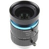
 Raspberry Pi HQ Camera Lens - 16mm TelephotoSPARKFUN
¥3,998~税込¥4,398~特価
1個
当日出荷から33日以内出荷
DescriptionThis is the 16mm C-mount telephoto lens from CGL Electronics Co. Ltd. for use with the Raspberry Pi HQ Camera Module. The lens produces a 10MP picture in a 1in image format and is easily interchangeable using the thumb screw and adapter inc
アズワン品番67-0427-28
 SparkFun Servo TriggerSPARKFUN
¥5,598税込¥6,158
1個
5日以内出荷
Servo Triggerは、小型ロボットなどのRCサーボモータの制御を簡単に行えるボードです。外部スイッチまたはロジック信号のサーボトリガにより、接続されたサーボモータの位置Aから位置Bに移動するように指示することができます。サーボトリガを使用するには、オンボードの半固定抵抗を使用してスタート/ストップ位置とトランジション時間を調整します。制御にはATTiny84マイクロコントローラを使用して、サーボ制御プログラムを実行しています。オンボードの各サーボトリガには、3つの半固定抵抗があります。Aはスイッチがオープンのときサーボが入る位置を設定し、Bはスイッチがクローズしたときにサーボが移動する位置を設定し、TはAからBに戻ってくるのにかかる時間を設定します。2つの動作モードがあり、裏面のジャンパ(SJ1)で切り替えられます。デフォルトはスイッチ開でA、スイッチ閉でBになるBistableモードで、SJ1をショートするとスイッチを押すたびにAB、ABを繰り返すOne shotモードになります。主な仕様コントローラ:ATTiny84推奨電圧:5V最大電圧:5.5V消費電流:5mA3つの制御設定A:スイッチがオープン時のサーボ位置の設定B:スイッチがクローズ時のサーボ位置の設定C:AからB、BからAに戻るのにかかる時間の設定入力極性を設定可能応答モードを設定可能アナログサーボと互換性があるISPヘッダピンを再プログラムに使用可能
アズワン品番63-3035-84
 Schmitt Trigger - CD40106BSPARKFUN
¥759税込¥835
1個
33日以内出荷
DescriptionThe CD40106BE consists of six Schmitt-trigger circuits. Each circuit functions as an inverter with Schmitt-trigger action on the input. The trigger switches at different points for positive- and negative-going signals. The difference between the positive-going voltage(VP)and the negative-going voltage(VN)is defined as hysteresis voltage(VH).FeaturesSchmitt trigger action with no external componentsHysteresis voltage typ. at 0.9V at VDD = 5V, 2.3V at VDD = 10V, and 3.5V at VDD = 15VNoise immunity greater than 50%No limit on input rise and fall timesStandardised, symmetrical output characteristics100% tested for quiescent current at 20sVMaximum input current of 1μA at 18 V over full package temperature range; 100nA at 18V and 25℃Low VDD to VSS current during slow input ramp
アズワン品番67-0420-89
 ArduinoMega 2560 R3SPARKFUN
¥18,980税込¥20,878
1個
33日以内出荷
DescriptionArduino is an open-source physical computing platform based on a simple i/o board and a development environment that implements the Processing/Wiring language. Arduino can be used to develop stand-alone interactive objects or can be connected to software on your computer(e.g. Flash, Processing, MaxMSP). The open-source IDE can be downloaded for free(currently for Mac OS X, Windows, and Linux).The Arduino Mega is a microcontroller board based on the ATmega2560. It has 54 digital input/output pins(of which 14 can be used as PWM outputs), 16 analog inputs, 4 UARTs(hardware serial ports), a 16 MHz crystal oscillator, a USB connection, a power jack, an ICSP header, and a reset button. It contains everything needed to support the microcontroller; simply connect it to a computer with a USB cable or power it with a AC-to-DC adapter or battery to get started.Never fear for accidental electrical discharge, either since since the Mega also includes a plastic base plate to protect it!The Mega 2560 R3 also adds SDA and SCL pins next to the AREF.In addition, there are two new pins placed near the RESET pin. One is the IOREF that allow the shields to adapt to the voltage provided from the board.The other is a not connected and is reserved for future purposes.The Mega 2560 R3 works with all existing shields but can adapt to new shields which use these additional pins.Not sure which Arduino or Arduino-compatible board is right for you? Check out our Arduino Buying Guide!FeaturesATmega2560 microcontrollerInput voltage - 7-12V54 Digital I/O Pins(14 PWM outputs)16 Analog Inputs256k Flash Memory16Mhz Clock Speed
アズワン品番67-0349-13
 Raspberry Pi 4 Case FanSPARKFUN
¥2,198税込¥2,418
1個
33日以内出荷
DescriptionThe Raspberry Pi 4 Case Fan works with Raspberry Pi 4 and the Raspberry Pi 4 Case. Designed for overclockers and other power users, it keeps your Raspberry Pi 4 at a comfortable operating temperature even under heavy load.The temperatu
アズワン品番67-0426-09
 SparkFun Qwiic Shield for Thing PlusSPARKFUN
¥1,598税込¥1,758
1個
33日以内出荷
DescriptionThe SparkFun Qwiic Shield for Thing Plus provides you with a quick and easy way to enter into SparkFun's Qwiic ecosystem with your Thing Plus or Feather boards. Since the Thing Plus and Feather footprints are interchangable, you can use th
アズワン品番67-0423-13
 Raspberry Pi HQ Camera Lens - 6mm Wide AngleSPARKFUN
¥24,980税込¥27,478
1個
予約販売
DescriptionThis is the 6mm CS-mount wide angle lens from CGL Electronics Co. Ltd. for use with the Raspberry Pi HQ Camera Module. The lens produces a 3MP picture in a 0.5in image format and is easily interchangeable using the thumb screw and adapter i
アズワン品番67-0427-29
 心拍センサーSPARKFUN
¥9,898税込¥10,888
1個
33日以内出荷
DescriptionHeart rate data can be really useful whether you're designing an exercise routine, studying your activity or anxiety levels or just want your shirt to blink with your heart beat. The problem is that heart rate can be difficult to measure. L
アズワン品番67-0437-01
 SparkFun Real Time Clock Module - RV-1805 QwiicSPARKFUN
¥7,798税込¥8,578
1個
33日以内出荷
DescriptionGet with the times, already! This SparkFun Real Time Clock(RTC)Module is a Qwiic-enabled breakout board for the RV-1805 chipset. The RTC is ultra-low power(running at only about 22nA in its lowest power setting)so it can use a supercapacitor for backup power instead of a normal battery. This means you get plenty of charge and discharge cycles without any degradation to the "battery." To make it even easier to get your readings, all communication is enacted exclusively via I2C, utilizing our handy Qwiic system so no soldering is required to connect it to the rest of your system. However, we still have broken out 0.1"-spaced pins in case you prefer to use a breadboard.This RTC module's built in RV-1805 has not one, but two internal oscillators:a 32.768kHz tuning fork crystal and a low power RC based oscillator and can automatically switch between the two using the more precise crystal to correct the RC oscillator every few minutes. This feature allows the module to maintain a very accurate date and time with the worst case being +/- about three minutes over a year. The RV-1805 also has a built in trickle charger so as soon as the RTC is connected to power the it will be fully charged in under 10 minutes and has the ability to switch power to other systems allowing it to directly turn on or off a power hungry device such as a microcontroller or RF engine.There is also the option to add a battery to the board if the supercapacitor just isn't going keep your project powered long enough(keep in mind, the supercap can hypothetically make the board keep time for around 35 days), you can solder on an external battery. That means you can let board sit with no power or connection to the outside world and the current hour/minute/second/date will be maintained.Note:The I2C address of the RV-1805 is 0x69 and is hardware defined. A multiplexer/Mux is required to communicate to multiple RV-1805 sensors on a single bus. If you need to use more than one RV-1805 sensor consider using the Qwiic Mux Breakout.The SparkFun Qwiic connect system is an ecosystem of I2C sensors, actuators, shields and cables that make prototyping faster and less prone to error. All Qwiic-enabled boards use a common 1mm pitch, 4-pin JST connector. This reduces the amount of required PCB space, and polarized connections mean you can't hook it up wrong.Get Started with the RV-1805 Real Time Clock Module GuideFeaturesOperating Voltage(Startup):1.6V - 3.6VOperating Voltage(Timekeeping):1.5V - 3.6VOperating Temperature:-40℃ - 85℃Time Accuracy:±2.0 ppmCurrent Consumption:22nA(Typ.)I2C Address:0xD2Supercapacitor for Backup Power2x Internal Oscillators2x Qwiic Connectors
アズワン品番67-0420-02
 Cherry MX Switch BreakoutSPARKFUN
¥799税込¥879
1個
33日以内出荷
DescriptionCherry MX Keyswitches are top-of-the-line mechanical keyboard switches. They're satisfyingly "clicky", reliable up to tens-of-millions of key presses, and a standard in gaming and programming keyboards across the globe. With the SparkFun Cherry MX Switch Breakout we have made the switches more easily adaptable to breadboard or perfboard-based projects. The Cherry MX Switch Breakout is a perfect prototyping tool for projects ranging from a single-key user-input to fully-custom 101-key keyboards.In addition to breaking out the switch contacts to breadboard-compatible headers, the Cherry MX Switch Breakout also provides access to an optional switch-mounted LED. Plus, the pin break-outs are designed with keyboard matrix-ing in mind, so you can interconnect as many boards as you'd like into a row-column configuration, keeping the I/O-pin requirements as low as possible.Note:If you are looking for a Cherry MX Switch to use with this breakout, we've got you covered! CLICK HERE!Get Started with the Cherry MX Switch GuideFeaturesSupport for 3mm LEDFootprint for LED current-limiting resistorFootprint for switch-isolating diodeChain-able in row/column matricesDesigned to match standard key spacing and keyboard row offsets
アズワン品番67-0419-91
 SparkFun Inventor's Kit for Arduino Uno - v4.1SPARKFUN
¥34,980税込¥38,478
1個
33日以内出荷
DescriptionThe SparkFun Inventor's Kit(SIK)for Arduino Uno is a great way to get started with programming and hardware interaction with the Arduino programming language. The SIK includes everything you need to complete five overarching projects consisting of 16 interconnected circuits that teach everything from blinking an LED to reading sensors. The culminating project is your very own autonomous robot! No previous programming or electronics experience is required to use this kit.The online guide contains step-by-step instructions with circuit diagrams and hookup tables for building each project and circuit with the included parts. Full example code is provided, new concepts and components are explained at point of use, and troubleshooting tips offer assistance if something goes wrong.The kit does not require any soldering and is recommended for beginners ages 10 and up who are looking for an Arduino starter kit. For SIK version 4.1 we took an entirely different approach to teaching embedded electronics. In previous versions of the SIK, each circuit focused on introducing a new piece of technology. With SIK v4.1, components are introduced in the context of the circuit you are building, and each circuit builds upon the last, leading up to a project that incorporates all of the components and concepts introduced throughout the guide. With new parts and a completely new strategy, even if you've used the SIK before, you're in for a brand-new experience!This version of the SIK replaces the SparkFun RedBoard Qwiic with the Arduino Uno(SMD version)and comes without the SIK guidebook and carrying case. With these components being swapped and removed, we were able to reduce the overall size and weight of the kit, making shipping cheaper and easier for anyone ordering internationally.Note:As stated above, this SIK does NOT include a carrying case or print guidebook.Get Started With the SparkFun Inventor's Kit v4.1 Experiment GuideExamplesProject 1:LightCircuit 1A:Blinking an LEDCircuit 1B:PotentiometerCircuit 1C:PhotoresistorCircuit 1D:RGB Night-LightProject 2:SoundCircuit 2A:BuzzerCircuit 2B:Digital TrumpetCircuit 2C:"Simon Says" GameProject 3:MotionCircuit 3A:Servo MotorsCircuit 3B:Distance SensorCircuit 3C:Motion AlarmProject 4:DisplayCircuit 4A:LCD "Hello, World!"Circuit 4B:Temperature SensorCircuit 4C:"DIY Who Am I?" GameProject 5:RobotCircuit 5A:Motor BasicsCircuit 5B:Remote-Controlled RobotCircuit 5C:Autonomous Robot
アズワン品番67-0424-34
 SparkFun Paper Circuits KitSPARKFUN
¥5,198税込¥5,718
1個
33日以内出荷
DescriptionWelcome to the world of paper circuits - creating electronic projects directly on paper using simple components! The SparkFun Paper Circuits Kit teaches the basics and fundamentals of creating an electric circuit without the need to solde
アズワン品番67-0424-37
 FLIR Lepton 2.5 - Thermal Imaging ModuleSPARKFUN
¥68,980税込¥75,878
1個
33日以内出荷
DescriptionThe FLIR Lepton(R)2.5 - Thermal Imaging Module is a radiometric-capable long wave infrared(LWIR)camera solution that is smaller than a dime, fits inside a smartphone, and is less expensive than traditional IR cameras. With a focal plane array of 80x60 active pixels, this Lepton easily integrates into native mobile-devices and other electronics as an IR sensor or thermal image sensor. The radiometric Lepton captures accurate, calibrated, and non-contact temperature data in every pixel.For large quantities:We currently have a limit of one per customer order on the FLIR Lepton 2.5 module due to supply chain issues as a result of COVID-19. If you need to place a distributor order please contact your sales rep and they will assist you. For bulk order for this module please visit our Volume Pricing Page for inquiries of stock. At this time, we cannot guarantee orders for this module but we will do what we can to work with you in fulfilling your request.FeaturesEffective Frame Rate:8.6 Hz(commercial application exportable)Input Clock:25-MHz nominal, CMOS IO Voltage LevelsOutput Format:User-selectable 14-bit, 8-bit(AGC applied), or 24-bit RGB(AGC and colorization applied)Pixel Size:17 μmRadiometric Accuracy:High gain:Greater of +/- 5℃ or 5%(typical)Low gain:Greater of +/- 10℃ or 10%(typical)Scene Dynamic Range:-10-140 ℃(high gain); up to 450℃(low gain)typicalSpectral Range:Longwave infrared, 8 μm to 14 μmTemperature Compensation:Automatic. Output image independent of camera temperature.Thermal Sensitivity:<50 mK(0.050° C)Video Data Interface:Video over SPIControl Port:CCI(I2C-like), CMOS IO Voltage LevelsPackage Dimensions - Socket Version(w×l×h):11.8×12.7×7.2 mmMechanical Interface:32-pin socket interface to standard Molex(R)socketNon-Operating Temperature Range:-40 ℃ to +80 ℃Optimum Temperature Range:-10℃ to +80℃Shock:1500 G @ 0.4 msArray format:80×60, progressive scanFOV - Diagonal:63.5°FOV - Horizontal:50°(nominal)Image Optimization:Factory configured and fully automatedNon-Uniformity Correction(NUC):Automatic with shutterSensor Technology:Uncooled VOx microbolometerSolar protection:IntegralInput Supply Voltage:2.8 V, 1.2 V, 2.5 V to 3.1 V IOPower Dissipation:150 mW(operating), 650 mW(during shutter event), 4 mW(standby)
アズワン品番67-0427-21
 SparkFun Pulse Oximeter and Heart Rate Sensor - MAX30101 & MAX32664 QwiicSPARKFUN
¥13,980税込¥15,378
1個
33日以内出荷
DescriptionThe SparkFun Pulse Oximeter and Heart Rate Sensor is an I2C based biometric sensor, utilizing two chips from Maxim Integrated:the MAX32664 Biometric Sensor Hub and the MAX30101 Pulse Oximetry and Heart Rate Module. While the latter does all the sensing, the former is an incredibly small and fast Cortex M4 processor that handles all of the algorithmic calculations, digital filtering, pressure/position compensation, advanced R-wave detection, and automatic gain control. We've provided a Qwiic connector to easily connect to the I2C data lines but you will also need to connect to two additional lines. This board is very small, measuring at 1in×0.5in(25.4mm×12.7mm), which means it will fit nicely on your finger without all the bulk.The MAX30101 does all the sensing by utilizing its internal LEDs to bounce light off the arteries and arterioles in your finger's subcutaneous layer and sensing how much light is absorbed with its photodetectors. This is known as photoplethysmography. This data is passed onto and analyzed by the MAX32664 which applies its algorithms to determine heart rate and blood oxygen saturation(SpO2). SpO2 results are reported as the percentage of hemoglobin that is saturated with oxygen. It also provides useful information such as the sensor's confidence in its reporting as well as a handy finger detection data point. To get the most out of the sensor we've written an Arduino Library to make it easy to adjust all the possible configurations.The SparkFun Qwiic connect system is an ecosystem of I2C sensors, actuators, shields and cables that make prototyping faster and less prone to error. All Qwiic-enabled boards use a common 1mm pitch, 4-pin JST connector. This reduces the amount of required PCB space, and polarized connections mean you can't hook it up wrong.Get Started with the Pulse Oximeter and Heart Rate Monitor Hookup GuideFeaturesSparkFun Pulse Oximeter and Heart Rate SensorMAX30101 and MAX32664 sensor and sensor hubQwiic connectors for power and I2C interfaceI2C Address:0x55MAX30101 - Pulse Oximeter and Heart-Rate SensorHeart-Rate Monitor and Pulse Oximeter Sensor in LED Reflective SolutionIntegrated Cover Glass for Optimal, Robust PerformanceUltra-Low Power Operation for Mobile DevicesFast Data Output CapabilityRobust Motion Artifact ResilienceMAX32664 - Ultra-Low Power Biometric Sensor HubBiometric Sensor Hub SolutionFinger-Based Algorithms Measure Pulse Heart Rate and Pulse Blood Oxygenation Saturation(SpO2)Both Raw and processed data are availableBasic Peripheral mix optimizes size and performance
アズワン品番67-0426-96
 SparkFun Arduino ProtoShield - Bare PCBSPARKFUN
¥1,998税込¥2,198
1個
予約販売
DescriptionThe SparkFun Arduino ProtoShield is a bare PCB with no attached or included parts that lets you customize your own Arduino shield using whatever circuit you can come up with! You will even be able to test your circuit or project to make sur
アズワン品番67-0422-24
 Mini Microswitch - SPDT Roller LeverSPARKFUN
¥569税込¥626
1個
33日以内出荷
DescriptionAlthough small in size, KW4-Z5F roller microswitches are rated for controlling electrical loads ranging from logic level(computer based circuits)to power duty switching(up to 16.1 A and 250 Vac). The package size of the subminiature switch
アズワン品番67-0421-81
 SparkFun Digital Sandbox Add-OnSPARKFUN
¥4,698税込¥5,168
1個
33日以内出荷
DescriptionThis is the Add-On kit for the SparkFun Digital Sandbox(DS)learning platform. With this add-on you will be able to perform the final three circuit experiments found in the DS Guide book which include making an electric musical instrument
アズワン品番67-0423-98
 SparkFun Inventor's Kit Bridge Pack for micro:bitSPARKFUN
¥15,980税込¥17,578
1個
33日以内出荷
DescriptionDo you own micro:bit or micro:bit Go Bundle and want to expand your skills with the new microcontroller? You are in luck! The SparkFun Inventor's Kit Bridge Pack for micro:bit was designed to provide you with an easy way to transform your m:b into full fledged learning kit! Each Bridge Pack includes all of the parts found in the SIK for micro:bit that aren't included with the Go Bundle. With the SIK Bridge Pack for micro:bit you will be able to complete circuits that will teach you how to read sensors, move motors, build Bluetooth(R)devices and more.The micro:bit is pocket-sized computer that lets you get creative with digital technology. Between the micro:bit and our shield-like bit boards you can do almost anything while coding, customizing and controlling your micro:bit from almost anywhere! You can use your micro:bit for all sorts of unique creations, from robots to musical instruments and more. At half the size of credit card, this versatile board has vast potential!Note:The Bridge Pack is NOT full SparkFun Inventor's Kit and only includes the parts to complement micro:bit Go Bundle or standalone board. That also means that this kit doesnotinclude micro:bit, which will need to be purchased separately.Get started with the micro:bit SIK Experiment GuideExamplesCircuit 0:Hello, micro:bit!Circuit 1:Blinking an LEDCircuit 2:Reading PotentiometerCircuit 3:Reading PhotoresistorCircuit 4:Driving an RGB LEDCircuit 5:Reading an SPDT SwitchCircuit 6:Reading Button PressCircuit 7:Reading the Temperature SensorCircuit 8:Using Servo MotorCircuit 9:Using BuzzerCircuit 10:Using the AccelerometerCircuit 11:Using the Compass
アズワン品番67-0424-21
 Amphenol FCI Clincher Connector Position, Female) COMシリーズSPARKFUN
¥649税込¥714
1個
予約販売
DescriptionThough the Clincher connector can be used with FFCs, we also like to use them with our FlexiForce sensors and other flex/force sensors found in theRecommended Productssection below.Note:Please be aware that we will not be able to accept returns on this connector if it has been closed. Sorry for any inconvenience this may cause.
アズワン品番67-0420-96
 Amphenol FCI Clincher Connector Position, Female) COMシリーズSPARKFUN
¥999税込¥1,099
1個
予約販売
DescriptionThough the Clincher connector can be used with FFCs, we also like to use them with our FlexiForce sensors and other flex/force sensors found in theRecommended Productssection below.Note:Please be aware that we will not be able to accept returns on this connector if it has been closed. Sorry for any inconvenience this may cause.
アズワン品番67-0420-95
 SparkFun Inventor's Kit for micro:bit v2SPARKFUN
¥17,980税込¥19,778
1個
33日以内出荷
DescriptionThe SparkFun Inventor's Kit(SIK)for micro:bit v2 is a great way to get creative, connected and coding with the micro:bit. The SIK for micro:bit v2 provides not only the micro:bit v2 board but everything you need to hook up and experiment with multiple electronic circuits! With the SIK for micro:bit v2 you will be able to complete circuits that will teach you how to read sensors, move motors, build Bluetooth(R)devices and more.The SparkFun Inventor's Kit for micro:bit is the latest and greatest in single-board computer kits. Surrounding the micro:bit v2 SIK is one core philosophy --- that anyone can(and should)experiment with cutting-edge electronics in a fun and playful way without breaking the bank.The kit does not require any soldering and is recommended for all users, from beginners to engineers. We have provided a complete Experiment Guide in the Documents tab for you to check out now! If you have ever been interested in learning about electronics, or if you have used the original SparkFun Inventor's Kit and are looking for something new, the SIK for micro:bit is the perfect kit for you!The micro:bit is a pocket-sized computer that lets you get creative with digital technology. Between the micro:bit and our shield-like bit boards you can do almost anything while coding, customizing and controlling your micro:bit from almost anywhere! You can use your micro:bit for all sorts of unique creations, from robots to musical instruments and more. At half the size of a credit card, this versatile board has vast potential!ExamplesCircuit 0:Hello, micro:bit!Circuit 1:Blinking an LEDCircuit 2:Reading a PotentiometerCircuit 3:Reading a PhotoresistorCircuit 4:Driving an RGB LEDCircuit 5:Reading an SPDT SwitchCircuit 6:Reading a Button PressCircuit 7:Reading the Temperature SensorCircuit 8:Using a Servo MotorCircuit 9:Using a BuzzerCircuit 10:Using the AccelerometerCircuit 11:Using the Compass
アズワン品番67-0424-61
 SparkFun Wireless Joystick KitSPARKFUN
¥13,980税込¥15,378
1個
33日以内出荷
DescriptionThe SparkFun Wireless Joystick Kit provides an easy way to control your next XBee project. Before the wireless joystick, radio-controlled projects used hobby RC transmitters, the same ones used for RC cars, boats and planes. The problem with these transmitters is that many aren't customizable, and the ones that are tend to be too expensive for many of us. The Wireless Joystick Kit offers a custom wireless solution for those who want to control their project their own way.Equipped with the increasingly popular SAMD21 onboard, all you need is to assemble the SparkFun Wireless Joystick into the configuration you want and add your own XBee and lithium ion battery into the provided sockets. The Wireless Joystick Kit can be assembled into a configuration that utilizes dual joysticks for better RC steering robots(like tanks)or a single joystick configuration with four 12mm momentary pushbuttons(a setup similar to what older game consoles used). We have provided a full Hookup Guide that gives assembly instructions, as well as a tank-steering motor controller tutorial to help get you started!Please be aware that the SparkFun Wireless Joystick Kit isNOT supported on Windows 7/8due to a lack of support drivers for those specific OS's.Note:This kit will need to be assembled before use, so a beginner's knowledge of soldering will be required. Additionally, in an effort to keep shipping rates down and make this kit available to people throughout the world without delay, there is no XBee or lithium ion battery included.Get Started with the Wireless Joystick Kit Guide
アズワン品番67-0424-08
 SparkFun 2D Barcode Scanner BreakoutSPARKFUN
¥20,980税込¥23,078
1個
予約販売
DescriptionThe SparkFun 2D Barcode Scanner Breakout is a nifty little breakout board featuring the DE2120 barcode scanner module from DYScan. The DE2120 reads 20 different barcode symbologies(both 1D and 2D)using a camera coupled with on-board image processing to identify and decode everything from UPC codes to QR codes. The module also features two LEDs:one for illumination and one to project the red line that you're used to seeing from laser-based scanners.This breakout board makes it easy to explore all of the capabilities of the DE2120 without dealing with finicky flat flex cables. The scanner's USB interface is exposed via the on-board USB-C connector. A buzzer and status LED are connected to the module through appropriate drive circuits and a push button tactile switch is provided on the "trigger" pin. When you're ready to incorporate the module into your embedded project, you can leverage the 5 pin header for direct access to the TTL serial pins, power pins, and trigger input.The module can be configured either by using the serial interface or by scanning command barcodes found in the Settings Manual.All keyboard, HID, and serial can be transmitted over the single USB-C connector. The DE2120 has the unique ability to enumerate all three protocols including a CDC serial driver so the device appears as a standard COM port.Get Started with the 2D Barcode Scanner Breakout Hookup GuideFeaturesUSB-C Connector for USB HID Interface and Virtual COM portReads 20 different symbologies1D SymbologiesUPC-AUPC-EEAN-8EAN-13Code 128GS1-128Code 39Code 93Code 11Interleaved 2-of-5Matrix 2-of-5Industrial 2-of-5CodabarMSIGS1 DataBarDatalogic 2-of-52D SymbologiesQR CodeData MatrixPDF 417Micro PDF 417Aztec Code
アズワン品番67-0430-36
 電子機器接続端子SPARKFUN
¥549税込¥604
1個
予約販売
DescriptionThese Clincher connectors from Amphenol FCI can be used to terminate Flat Flexible Cables(FFCs)to an easy-to-use standard header. Simply insert the end of the cable into the connector and press it closed. The teeth inside the connector will "clinch" around the conductors and break them out to three male 0.1" spaced pin headers!Though the Clincher connector can be used with FFCs, we also like to use them with our FlexiForce sensors and other flex/force sensors found in theRecommended Productssection below.Note:Please be aware that we will not be able to accept returns on this connector if it has been closed. Sorry for any inconvenience this may cause.
アズワン品番67-0395-68
 Red Hat Co.Lab Farm KitSPARKFUN
¥5,498税込¥6,048
1個
33日以内出荷
DescriptionIn this kit, you'll find everything you need to build an open source farm.The Red Hat Co.Lab Farm kit packs three activities into one small box:First, learn how breadboards work and experiment with creating simple circuits by adding
アズワン品番67-0421-94
 SparkFun Qwiic Alphanumeric Display - COMシリーズSPARKFUN
¥2,998税込¥3,298
1個
33日以内出荷
DescriptionThe SparkFun Alphanumeric Display Arduino library makes printing strings to the display as easy as calling the print()function. With this library, you'll be able to send I2C commands to the VK16K33 LED driver chip to light up segments(including the decimal point or colon)and even scroll your string across the display. You can download the library through the Arduino library manager by searching 'SparkFun Alphanumeric Display' or you can get the GitHub repo as a .zip file and install the library from there.The SparkFun Qwiic Connect System is an ecosystem of I2C sensors, actuators, shields and cables that make prototyping faster and less prone to error. All Qwiic-enabled boards use a common 1mm pitch, 4-pin JST connector. This reduces the amount of required PCB space, and polarized connections mean you can't hook it up wrong.Get Started with the Qwiic Alphanumeric Display Hookup GuideFeaturesOperating Voltage:3.3VIntegrated RC oscillatorMaximum display segment numbers:128 patterns13×3 matrix key scan circuit16-step dimming circuitI2C Addresses:0x70(0x71, 0x72, 0x73)2x Qwiic connectors2x Wall Mounting Points
アズワン品番67-0421-61
 SparkFun Qwiic Alphanumeric Display - COMシリーズSPARKFUN
¥2,998税込¥3,298
1個
33日以内出荷
DescriptionThe SparkFun Alphanumeric Display Arduino library makes printing strings to the display as easy as calling the print()function. With this library, you'll be able to send I2C commands to the VK16K33 LED driver chip to light up segments(including the decimal point or colon)and even scroll your string across the display. You can download the library through the Arduino library manager by searching 'SparkFun Alphanumeric Display' or you can get the GitHub repo as a .zip file and install the library from there.The SparkFun Qwiic Connect System is an ecosystem of I2C sensors, actuators, shields and cables that make prototyping faster and less prone to error. All Qwiic-enabled boards use a common 1mm pitch, 4-pin JST connector. This reduces the amount of required PCB space, and polarized connections mean you can't hook it up wrong.Get Started with the Qwiic Alphanumeric Display Hookup GuideFeaturesOperating Voltage:3.3VIntegrated RC oscillatorMaximum display segment numbers:128 patterns13×3 matrix key scan circuit16-step dimming circuitI2C Addresses:0x70(0x71, 0x72, 0x73)2x Qwiic connectors2x Wall Mounting Points
アズワン品番67-0421-62
 SparkFun Qwiic Alphanumeric Display - COMシリーズSPARKFUN
¥3,198税込¥3,518
1個
33日以内出荷
DescriptionThe SparkFun Alphanumeric Display Arduino library makes printing strings to the display as easy as calling the print()function. With this library, you'll be able to send I2C commands to the VK16K33 LED driver chip to light up segments(including the decimal point or colon)and even scroll your string across the display. You can download the library through the Arduino library manager by searching 'SparkFun Alphanumeric Display' or you can get the GitHub repo as a .zip file and install the library from there.The SparkFun Qwiic Connect System is an ecosystem of I2C sensors, actuators, shields and cables that make prototyping faster and less prone to error. All Qwiic-enabled boards use a common 1mm pitch, 4-pin JST connector. This reduces the amount of required PCB space, and polarized connections mean you can't hook it up wrong.Get Started with the Qwiic Alphanumeric Display Hookup GuideFeaturesOperating Voltage:3.3VIntegrated RC oscillatorMaximum display segment numbers:128 patterns13×3 matrix key scan circuit16-step dimming circuitI2C Addresses:0x70(0x71, 0x72, 0x73)2x Qwiic connectors2x Wall Mounting Points
アズワン品番67-0421-64
 SparkFun Qwiic Alphanumeric Display - COMシリーズSPARKFUN
¥2,998税込¥3,298
1個
33日以内出荷
DescriptionThe SparkFun Alphanumeric Display Arduino library makes printing strings to the display as easy as calling the print()function. With this library, you'll be able to send I2C commands to the VK16K33 LED driver chip to light up segments(including the decimal point or colon)and even scroll your string across the display. You can download the library through the Arduino library manager by searching 'SparkFun Alphanumeric Display' or you can get the GitHub repo as a .zip file and install the library from there.The SparkFun Qwiic Connect System is an ecosystem of I2C sensors, actuators, shields and cables that make prototyping faster and less prone to error. All Qwiic-enabled boards use a common 1mm pitch, 4-pin JST connector. This reduces the amount of required PCB space, and polarized connections mean you can't hook it up wrong.Get Started with the Qwiic Alphanumeric Display Hookup GuideFeaturesOperating Voltage:3.3VIntegrated RC oscillatorMaximum display segment numbers:128 patterns13×3 matrix key scan circuit16-step dimming circuitI2C Addresses:0x70(0x71, 0x72, 0x73)2x Qwiic connectors2x Wall Mounting Points
アズワン品番67-0421-63
 555 TimerSPARKFUN
¥339税込¥373
1個
33日以内出荷
DescriptionThis is a common 555 timer/oscillator from TI. A classic for all of those first year circuits projects where you need to blink an LED, generate tone, and thousands of other great beginning projects. Google around for a huge list of resourc
アズワン品番67-0421-55
 SparkFun MicroMod Data Logging Carrier BoardSPARKFUN
¥7,098税込¥7,808
1個
33日以内出荷
DescriptionThe SparkFun MicroMod Data Logging Board offers a highly customizable, low-power data logging platform using the MicroMod system allowing you to choose your own Processor to pair with the Carrier Board. The Data Logging Carrier Board breaks out connections for I2C via a Qwiic connector or standard 0.1"-spaced PTH pins along with SPI and serial UART connections for logging data from peripheral devices using those communication protocols.The Data Logging Carrier Board allows you to control power to both the Qwiic connector on the board and a dedicated 3.3V power rail for non-Qwiic peripherals so you can pick and choose when to power the peripherals you are monitoring the data from. It also features a charging circuit for single-cell Lithium-ion batteries along with a separate RTC battery-backup circuit to maintain power to a real-time clock circuit on your Processor Board.MicroMod is a modular interface ecosystem that connects a microcontroller "processor board" to various "carrier board" peripherals. Utilizing the M.2 standard, the MicroMod standard is designed to easily swap out processors on the fly. Pair a specialized carrier board for the project you need with your choice of compatible processor!Get Started with the MicroMod Data Logging Carrier Board GuideFeaturesM.2 MicroMod ConnectormicroSD socketUSB-C Connector3.3V 1A Voltage RegulatorQwiic ConnectorBoot/Reset ButtonsRTC Backup Battery Charge CircuitIndependent 3.3V regulators for Qwiic bus and peripheral add-onsControlled by digital pins on Processor Board to enable low power sleep modesPhillips #0 M2.5x3mm screw included
アズワン品番67-0423-16
 PureThermal Mini Pro JST-SR with FLIR Lepton 3.5SPARKFUN
¥129,800税込¥142,780
1個
33日以内出荷
DescriptionThe new PureThermal Mini Pro JST-SR with Thermal by FLIR is a hackable thermal camera for the FLIR Lepton thermal imaging camera core. Just like its PureThermal 2 predecessor, it ships pre-configured to operate as a plug-and-play UVC 1.0 USB thermal webcam that will work with standard webcam and video apps on all major platforms using a JST-SR to USB Cable, or your own custom cable. For developers, its reference firmware and viewer software are open source.It has multiple connection options such as solder straight to the board or a custom cable using the JST-SR port. The PTMini Pro also features four mounting holes, less complex circuitry, and perhaps best of all, USB DFU. This is a development kit ready to be embedded into a production system.Each board comes with a FLIR Lepton 3.5.The FLIR Lepton(R)is a radiometric-capable LWIR camera solution that is smaller than a dime, fits inside a smartphone, and is one tenth the cost of traditional IR cameras. Using focal plane arrays of either 160x120 or 80x60 active pixels, Lepton easily integrates into native mobile-devices and other electronics as an IR sensor or thermal imager. The radiometric Lepton captures accurate, calibrated, and noncontact temperature data in every pixel of each image.FeaturesPureThermal:Compatible with all production FLIR Leptons, including radiometric 2.5 and 3.5 cores9 Hz color video over usb using the USB UVC classSTM32F412 ARM microprocessor - execute on-board image processing without need for an external systemOpen source reference firmware:GroupGets PureThermal GithubWorks with GetThermal - our custom open source thermal video display software for macOS and Linux with radiometric supportDFU over USB using a JST-SR port to USB cable, or a modified USB cable and the through holes.Four mounting holesCompact form-factor ready to be embedded into production systemsFLIR Lepton 3.5:Thermal sensitivity:< 50 mK(0.050℃)Spectral Range:8 - 14 microns(nominal)Long Wave Infrared(LWIR)Resolution:160h×120v pixelsRadiometric Accuracy - High Gain Mode:Greater of +/- 5℃ or 5%(typical); Low Gain Mode:Greater of +/- 10℃ or 10%(typical)Scene Dynamic Range - High Gain Mode:-10° to +140℃; Low Gain Mode:-10° to +400℃(at room temperature), -10° to +450℃(typical)Pixel Size:12 micrometersFrame Rate:8.7 Hz(effective)Output Format:User-selectable 14-bit, 8-bit(AGC applied), or 24-bit RGB(AGC and colorization applied)Horizontal Field of View(HFOV):57°Lens Type:f/1.1Size(w×l×h):10.50×12.70×7.14 mmWeight:0.9 gramsPower Consumption:150 mW typical, 650 mW during shutter event, 5mW standbyOptimum Operating Temperature Range:-10℃ to + 80℃
アズワン品番67-0423-44
 Actuonix PQ12-100-6-R Micro-ActuatorSPARKFUN
¥47,980税込¥52,778
1個
予約販売
DescriptionThe PQ12 series of micro linear actuators are ideal for applications requiring precise positioning and compact size. Weighing in at just 22 grams, the PQ12 is incredibly light as well as compact. The affordably-priced PQ12 is the most powerful actuator of it's size. This is why it has become a popular choice for OEM manufacturers as well as Arduino and RC hobbyists. Some industries where the PQ12 are in use include:prosthetics, robotics, medical, simulation.The PQ12-R series of linear servos operate as a direct replacement for standard rotary servos. They use the same standard 3 wire connector, ground power and control. Regardless of how you drive your servos, be it with an RC receiver, an Arduino board, or a VEX micro-controller, the PQ12-R servo will function in place of a regular servo, but with the added benefit of providing linear motion. The PQ12-R is available in a 20mm stroke coupled with gear ratio options of 30:1, 63:1 and 100:1 cover a large variety of applications.The PQ12-100-6-R has:a 100:1 gear ratio for maximum lifting force; 6VDC operating voltage; and a servo(PWM)interface. This powerful little actuator can lift 50N(~5kg)!The datasheet doesn't mention a minimum operating voltage, but we've tested this actuator at 5VDC and it seems to work just fine. The maximum force and movement speed are reduced of course.FeaturesGearing Option:100:1Peak Power Point:40N @ 6mm/sPeak Efficiency Point:20N @ 8mm/sMax Speed(no load):10mm/sMax Force(lifted):50NMax Side Load:10NBack Drive Force:35NStroke:20 mmInput Voltage:6 VDCStall Current:550mA @ 6VMass:22gOperating Temperature -10℃ to +50℃Positional Repeatability:±0.1mmMechanical Backlash:0.25 mmAudible Noise:55dB @ 45cmIngress Protection:IP-54Maximum Duty Cycle:20%PWM(Servo)signal:Fully retracted:2.0ms @ 50HzFully extended:1.0ms @ 50Hz
アズワン品番67-0426-44
 SparkFun Qwiic Dual Solid State RelaySPARKFUN
¥39,980税込¥43,978
1個
33日以内出荷
DescriptionThe SparkFun Qwiic Dual Solid State Relay is a power delivery board that allows users to switch two AC loads from a low power microcontroller using the SparkFun Qwiic connect system. The board features two 25A/250VAC solid state relays that utilize the Zero Cross Trigger method so you can toggle two loads on a 60Hz AC carrier signal on and off up to 120 times per second!An ATTiny84 acts as the "brain" of the SparkFun Qwiic Dual Solid Relay to accept I2C commands to toggle the two relays as well as a few other special commands. The I2C address of the ATtiny84A is software configurable so, if you have a seriously big power project in mind, you could daisy chain over 100 Qwiic Dual Solid State Relays.Messing with such high voltage is dangerous! We've included many safety precautions onto the PCB including ground isolation between the relay and other circuitry and a milled out area isolating each side of AC. However, with all the safety precautions included with the SparkFun Qwiic Dual Solid State Relay, this is still a power accessory for users who are experienced around, and knowledgeable about high AC voltage. If you're not comfortable with handling AC voltage in this way, you may want to check out the IoT Power Relay instead.Note:The relays are rated for a max of 25A with forced air cooling. If you do not have forced air cooling, 10A max through the relays is recommended.The SparkFun Qwiic connect system is an ecosystem of I2C sensors, actuators, shields and cables that make prototyping faster and less prone to error. All Qwiic-enabled boards use a common 1mm pitch, 4-pin JST connector. This reduces the amount of required PCB space, and polarized connections mean you can't hook it up wrong.Get Started with the SparkFun Qwiic Dual Solid State Relay GuideFeaturesOperating Voltage:2.5-3.6V(3.3V recommended)I2C Address:0x0A(Default)0x0B(Alternate via jumper select)Load Voltage Range:12-280VACMax Current(Through Relay):25A(240VAC with forced air cooling)Zero Cross TriggerNormally Open Circuit Only2x Qwiic Connector
アズワン品番67-0421-58
 SparkFun ProtoShield KitSPARKFUN
¥4,998税込¥5,498
1個
33日以内出荷
DescriptionThe SparkFun ProtoShield Kit lets you customize your own Arduino shield using whatever circuit you can come up with and then test it to make sure everything is working the way it should! The SparkFun ProtoShield Kit is based off the Arduino R3's footprint that allows you to easily incorporate it with favorite Arduino-based device.One of our favorite features with this version of the ProtoShield Kit is the solderable-like breadboard prototyping area! Half of this area was designed with a breadboard in mind. On the underside of the shield you will be able to see open jumper pads between each through hole to make a connection like a breadboard. Once you add a component, simply add a solder jumper between holes to make a connection. For those that prefer the standard prototyping pads, we left the other side(near the BlueSMiRF and Serial UART ports)as is.We have also moved the prototype testing components(those used to make sure your circuit works effectively)off of the "mainland" of the shield and onto a ProtoSnap styled, removable PCB. On this test area you will find soldering areas for the two yellow 3mm LEDs(as well as pins to control and power them), two 330 Ohm resistors, a 10K Ohm resistor, and a pushbutton.Note:Since this product is a kit, assembly and a basic knowledge of soldering will be required. The SparkFun ProtoShield Kit does not come pre-assembled.Get Started With the SparkFun ProtoShield Kit GuideFeaturesArduino R3 FootprintSoldering KitSolderable-Like BreadboardBlueSMiRF or Comparable 6-pin PinsDetachable Test Area
アズワン品番67-0422-25
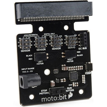 SparkFun moto:bit - micro:bit Carrier Board QwiicSPARKFUN
¥9,398税込¥10,338
1個
33日以内出荷
DescriptionThe SparkFun moto:bit is a fully loaded "carrier" board for the micro:bit that, when combined with the micro:bit, provides you with a fully functional robotics platform. The moto:bit offers a simple, beginner-friendly robotics controller capable of operating a basic robotics chassis. Onboard each moto:bit are multiple I/O pins, as well as a vertical Qwiic connector, capable of hooking up servos, sensors and other circuits. At the flip of the switch you can get your micro:bit moving!The moto:bit connects to the micro:bit via an updated SMD, edge connector at the top of the board, making setup easy. This creates a handy way to swap out micro:bits for programming, while still providing reliable connections to all of the different pins on the micro:bit. We have also included a basic barrel jack on the moto:bit that is capable of providing power to anything you connect to the carrier board.The micro:bit is a pocket-sized computer that lets you get creative with digital technology. Between the micro:bit and our shield-like bit boards you can do almost anything while coding, customizing and controlling your micro:bit from almost anywhere! You can use your micro:bit for all sorts of unique creations, from robots to musical instruments and more. At half the size of a credit card, this versatile board has vast potential!Note:The SparkFun moto:bit doesNOTinclude a micro:bit board. The micro:bit will need to be purchased separately.Get started with the moto:bit GuideFeaturesMore reliable Edge connector for easy use with the micro:bitFull H-Bridge for control of two motorsControl servo motorsVertical Qwiic ConnectorI2C port for extending functionalityPower and battery management onboard for the micro:bit
アズワン品番67-0422-89
 CO2 Humidity and Temperature Sensor - SCD30SPARKFUN
¥23,980税込¥26,378
1個
33日以内出荷
DescriptionThe SCD30 from Sensirion is a high quality Nondispersive Infrared(NDIR)based CO2 sensor capable of detecting 400 to 10000ppm with an accuracy of ±(30ppm+3%). In order to improve accuracy the SCD30 has temperature and humidity sensing built-in, as well as commands to set the current altitude. For additional accuracy the SCD30 also accepts ambient pressure readings!We've written an Arduino library to make reading the CO2, humidity, and temperature very easy. It can be downloaded through the Arduino Library manager:search for 'SparkFun SCD30' or it can be found in theDocumentstab above.The SCD30 Humidity and Temperature Sensor can also be automatically detected, scanned, configured, and logged using the OpenLog Artemis datalogger system. No programming, soldering, or setup required!Note:The SCD30 has an automatic self-calibration routine. Sensirion recommends 7 days of continuous readings with at least 1 hour a day of 'fresh air' for self-calibration to complete.FeaturesPower supply voltage:3.3V - 5.5VNDIR CO2 sensor technologyIntegrated temperature and humidity sensorBest performance-to-price ratioDual-channel detection for superior stabilitySmall form factor:35 mm×23 mm×7 mmMeasurement range:400 ppm - 10.000 ppmAccuracy:±(30 ppm + 3%)Current consumption:19 mA @ 1 meas. per 2 s.Energy consumption:120 mJ @ 1 measurementFully calibrated and linearizedDigital interface UART or I2C
アズワン品番67-0430-35
 SparkFun Qwiic Alphanumeric Display - WhiteSPARKFUN
¥2,998税込¥3,298
1個
33日以内出荷
DescriptionWe are quite familiar with seven-segment displays. We see them on our alarm clocks, ovens, and microwaves. By adding more segments to each digit you can display more than just numbers! Introducing the brand new SparkFun Qwiic Alphanumeric Display. These white fourteen-segment digits allow you display all sorts of numbers, characters, and symbols. With Qwiic, simply plug it in and go. No soldering, no figuring out which is SDA or SCL, and no voltage regulation or translation required!The SparkFun Alphanumeric Display Arduino library makes printing strings to the display as easy as calling the print()function. With this library, you'll be able to send I2C commands to the VK16K33 LED driver chip to light up segments(including the decimal point or colon)and even scroll your string across the display. You can download the library through the Arduino library manager by searching 'SparkFun Alphanumeric Display' or you can get the GitHub repo as a .zip file and install the library from there.The VK16K33 also supports I2C address configuration. Simply close a combination of the address jumpers on the back and you can communicate with up to four displays on the same bus. Our slim board design also features detachable stand off holes, vertical Qwiic connectors, and internal mounting holes.The SparkFun Qwiic Connect System is an ecosystem of I2C sensors, actuators, shields and cables that make prototyping faster and less prone to error. All Qwiic-enabled boards use a common 1mm pitch, 4-pin JST connector. This reduces the amount of required PCB space, and polarized connections mean you can't hook it up wrong.Get Started with the Qwiic Alphanumeric Display Hookup GuideFeaturesWhite displayOperating Voltage:3.3VIntegrated RC oscillatorMaximum display segment numbers:128 patterns13×3 matrix key scan circuit16-step dimming circuitI2C Addresses:0x70(0x71, 0x72, 0x73)2x Qwiic connectors2x Wall Mounting Points
アズワン品番67-0421-87
 Garmin LIDAR-Lite v4 LED - Distance Measurement SensorSPARKFUN
¥21,980税込¥24,178
1個
33日以内出荷
DescriptionThe LIDAR-Lite v4 LED sensor is the next step in the LIDAR-Lite line. A small, lightweight, low-power optical ranging sensor. It's the first to incorporate ANT profile wireless networking technology into an optical sensor. Its built-in nRF52840 processor means that developers can create custom applications, or be operated as a stand-alone device right out of the box by using the preloaded stock application.Like the LIDAR-Lite v3 and LIDAR-Lite v3HP sensors; it can also be directly connected to an external micro-controller running a custom user application. As such, it provides a highly adaptable option for OEM and maker applications in robotics, Internet of Things, and unmanned vehicles ― or any application where an ultrasonic sensor might otherwise be used. It's perfect as the basic building block for applications where wireless capabilities, small size, light weight, low power consumption and high performance are important factors in a short-range, 10-meter, optical distance measuring sensor.The LIDAR-Lite v4 requires an external 5VDC power source and soldering is required. This Time-of-Flight ranging module uses a LED and optics for ranging. It does not use a laser; therefore, it is inherently eye-safe under normal usage.FeaturesResolution:1 cmMeasurement repeatability:As measured indoors to a 90% reflective target1 cm is equivalent to 1 standard deviationUsing "high accuracy" mode, with averaging:+/- 1 cm to 2 meters+/- 2 cm to 4 meters+/- 5 cm to 10 metersRange:5 cm to 10 meters(as measured from back of unit)Update rate:I2C = >200 Hz typicalANT(R)= up to 200 Hz to a 90% target indoors at 2m in normal operating modeInterface:I2C or ANT; user configurable for SPI using the Nordic SDKPower(operating voltage):4.75 - 5.25 VDCCurrent consumption:2mA idle, 85mA during acquisitionOperating temperature:-20 to 60° CLED wavelength:940 nmBeam divergence:4.77°Optical aperture:14.9 mmUnit size(HxWxD):2.1"×0.8"×0.9"(52.2×21.2×24.0 mm)Weight:14.6 g(0.5 oz)
アズワン品番67-0427-09