カテゴリ
- 学童・教育用品(113)
- 制御機器(5)
- 測定用品(3)
- 空調・電設資材(2)
- 安全保護具(1)
- パソコン/周辺機器(1)
絞り込み
ブランド
- SPARKFUN
- ESET(26)
- キヤノンITソリューションズ(1)
- RS PRO(356)
- 長谷川工業(302)
- BMW(168)
- ホンダ(83)
- シュナイダーエレクトリック(73)
- Mitutoyo(ミツトヨ)(68)
- KEMET(51)
- DUCATI(49)
- KTM(30)
- SKC(環境測定)(30)
- 三菱ふそう(29)
- piaggio(ピアッジオグループ)(29)
- UnitGarage (ユニットガレージ)(23)
- DRAG SPECIALTIES(ドラッグスペシャリティーズ)(22)
- SKF(日本エスケイエフ)(16)
- エステー(15)
- ブランドをもっと見る
エコロジープロダクト
 RoHS10物質対応(1)
「eset」の検索結果
 MPLAB PICkit 4 In-Circuit DebuggerSPARKFUN
¥45,980税込¥50,578
1個
当日出荷
DescriptionThis is the PICkit 4, the official programmer from Microchip. The PICkit 4 allows debugging and programming of PIC(R), dsPIC(R), AVR, SAM and CEC flash microcontrollers and MPUs using the powerful graphical user interface of the MPLAB X Integrated Development Environment(IDE). The MPLAB PICkit 4 is connected to a PC using a high-speed 2.0 USB interface and can be connected to the target via an 8-pin Single In-Line(SIL)connector. The connector uses two device I/O pins and the reset line to implement in-circuit debugging and In-Circuit Serial Programming(TM)(ICSP(TM)). An additional micro SD card slot and the ability to be self-powered from the target means you can take your code with you and program on the go. Comes with a USB to micro-B USB cable.FeaturesPowered by a high-speed USB 2.0, no external power requiredReal-time executionMPLAB X IDE compatible(free copy included)Built-in over-voltage/short circuit monitorFirmware upgradeable from PC/web downloadFully enclosedTarget voltage of 1.20V to 5.5VCan supply up to 50mA of power to the targetMinimal current consumption at <100μA from targetDiagnostic LEDs(power, busy, error)Read/write program and data memory of microcontrollerErase of program memory space with verificationFreeze-peripherals at breakpoint8-pin single in-line header supports advanced interfaces such as 4-wire JTAG and Serial Wire Debug with streaming Data GatewayBackward compatible for demo boards, headers and target systems using 2-wire JTAG and ICSP
アズワン品番67-0425-08
 Raspberry Pi Zero CaseSPARKFUN
¥2,298税込¥2,528
1個
当日出荷
DescriptionThe Raspberry Pi Zero Case has been designed to fit both the Pi Zero and the Pi Zero W. These official cases consist of several parts and protect the Raspberry Pi Zero from things like rogue wires that might short it out while still allowing full access to the board. Simply snap the RPi into the bottom half of the enclosure, then snap on a desired top. No tools required!Each case has a standard base featuring a cut-out to allow access to the GPIO, and a choice of three lids:a standard lid, a GPIO lid(allowing access to the GPIO pins from above)and a camera lid(which, when used with the short camera cable supplied, allows the Raspberry Pi camera to be fitted neatly inside it). Additionally, each case includes a 4cm long CSI cable and four rubber feet.Note:This case doesNOTinclude a Raspberry Pi or Camera Module.
アズワン品番67-0425-31

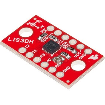 SparkFun Triple Axis Accelerometer Breakout - LIS3DHSPARKFUN
¥2,198税込¥2,418
1個
5日以内出荷
DescriptionThe LIS3DH Breakout is a smart, low-power, three-axis, capacitive micro-machined accelerometer with 12 bits of resolution that you can use to add translation detection to your project. It would be classified as a 3DoF, or 3 Degrees of Free
アズワン品番67-0426-60
 Resistor Network - 330 Ohm 6-pin bussedSPARKFUN
¥289税込¥318
1個
5日以内出荷
仕様●抵抗値:330Ω●ピン数:6ピンアズワン品番67-0453-16
 ArduinoMega 2560 R3SPARKFUN
¥18,980税込¥20,878
1個
33日以内出荷
DescriptionArduino is an open-source physical computing platform based on a simple i/o board and a development environment that implements the Processing/Wiring language. Arduino can be used to develop stand-alone interactive objects or can be connected to software on your computer(e.g. Flash, Processing, MaxMSP). The open-source IDE can be downloaded for free(currently for Mac OS X, Windows, and Linux).The Arduino Mega is a microcontroller board based on the ATmega2560. It has 54 digital input/output pins(of which 14 can be used as PWM outputs), 16 analog inputs, 4 UARTs(hardware serial ports), a 16 MHz crystal oscillator, a USB connection, a power jack, an ICSP header, and a reset button. It contains everything needed to support the microcontroller; simply connect it to a computer with a USB cable or power it with a AC-to-DC adapter or battery to get started.Never fear for accidental electrical discharge, either since since the Mega also includes a plastic base plate to protect it!The Mega 2560 R3 also adds SDA and SCL pins next to the AREF.In addition, there are two new pins placed near the RESET pin. One is the IOREF that allow the shields to adapt to the voltage provided from the board.The other is a not connected and is reserved for future purposes.The Mega 2560 R3 works with all existing shields but can adapt to new shields which use these additional pins.Not sure which Arduino or Arduino-compatible board is right for you? Check out our Arduino Buying Guide!FeaturesATmega2560 microcontrollerInput voltage - 7-12V54 Digital I/O Pins(14 PWM outputs)16 Analog Inputs256k Flash Memory16Mhz Clock Speed
アズワン品番67-0349-13
 SparkFun FTDI Starter Kit - 3.3VSPARKFUN
¥5,998税込¥6,598
1個
33日以内出荷
DescriptionThe SparkFun 3.3V FTDI Starter Kit gives you just what you need to get started with FTDI FT232RL USB to serial IC. The pinout of the included board matches the FTDI cable standard to work with official Arduino and cloned 3.3V Arduino boards. It can also be used for general serial applications. The major difference with this board is that it brings out the DTR pin as opposed to the RTS pin of the FTDI cable. The DTR pin allows an Arduino target to auto-reset when a new Sketch is downloaded. This is a really nice feature to have and allows a sketch to be downloaded without having to hit the reset button. This board will auto reset any Arduino board that has the reset pin brought out to a 6-pin connector.The SparkFun FTDI Basic Breakout was designed to decrease the cost of Arduino development and increase ease of use(the auto-reset feature rocks!). Our Arduino Pro and LilyPad boards use this type of connector.The included cable is a USB 2.0 type B to Mini-B 5-pin black cable.
アズワン品番67-0424-75
 Schmitt Trigger - CD40106BSPARKFUN
¥759税込¥835
1個
33日以内出荷
DescriptionThe CD40106BE consists of six Schmitt-trigger circuits. Each circuit functions as an inverter with Schmitt-trigger action on the input. The trigger switches at different points for positive- and negative-going signals. The difference between the positive-going voltage(VP)and the negative-going voltage(VN)is defined as hysteresis voltage(VH).FeaturesSchmitt trigger action with no external componentsHysteresis voltage typ. at 0.9V at VDD = 5V, 2.3V at VDD = 10V, and 3.5V at VDD = 15VNoise immunity greater than 50%No limit on input rise and fall timesStandardised, symmetrical output characteristics100% tested for quiescent current at 20sVMaximum input current of 1μA at 18 V over full package temperature range; 100nA at 18V and 25℃Low VDD to VSS current during slow input ramp
アズワン品番67-0420-89
 Crystal 32kHzSPARKFUN
¥579税込¥637
1個
33日以内出荷
DescriptionStandard 'Watch' or Real-Time-Clock crystal. 32.768kHz means it is precisely half of a 16-bit counter. Start counting at 0x8000(or 32768). When the counter rolls over from 65535 to 0, then you know that exactly one second has passed. Reset the interrupt, reset the counter, and start counting again! Rated at 12.5pF load capacitance, 35K ohm max(18K ohm typical)series resistance, and +/- 20ppm stability. Small cylinder package.
アズワン品番67-0429-94
 Mini Pushbutton SwitchSPARKFUN
¥179税込¥197
1個
33日以内出荷
We use these little buttons on everything! These Miniature Single Pole Single Throw switches have a good click to them and are breadboard friendly. Perfect as a tactile reset switch. These buttons are rated up to 50mA.
アズワン品番67-0452-50
 SparkFun Beefy 3 - FTDI Basic BreakoutSPARKFUN
¥5,798税込¥6,378
1個
33日以内出荷
DescriptionThis is SparkFun Beefy 3 FTDI Basic Breakout for the FTDI FT231X USB to serial IC. The pinout of this board matches the FTDI cable to work with official Arduino and cloned 3.3V Arduino boards. It can also be used for general serial applications. Built upon the same foundation as our 3.3V SparkFun FTDI Basic Breakout, the Beefy 3 is equipped with an AP2112K voltage regulator making this FTDI basic breakout board capable of handling a current load of up to 600 mA! With the addition of a more "Beefy" voltage regulator your will now be able to power a 3.3V project directly from the FTDI. The pinout of this board matches the FTDI cable to work with official Arduino and cloned 3.3V Arduino boards.This board brings out the DTR pin as opposed to the RTS pin of the FTDI cable. The DTR pin allows an Arduino target to auto-reset when a new Sketch is downloaded. This is a really nice feature to have and allows a sketch to be downloaded without having to hit the reset button. This board will auto reset any Arduino board that has the reset pin brought out to a 6-pin connector. The pins labeled BLK and GRN correspond to the colored wires on the FTDI cable. The black wire on the FTDI cable is GND, green is DTR. Use these BLK and GRN pins to align the FTDI basic board with your Arduino target.There are pros and cons to the FTDI Cable vs the FTDI Basic. This board has TX and RX LEDs that allow you to actually see serial traffic on the LEDs to verify if the board is working, however this board now requires a Micro-B USB cable. The FTDI Cable is well protected against the elements, but is large and cannot be embedded into a project as easily. The FTDI Basic uses DTR to cause a hardware reset where the FTDI cable uses the RTS signal.This board was designed to decrease the cost of Arduino development and increase ease of use(the auto-reset feature rocks!). Our Arduino Pro and LilyPad boards use this type of connector.
アズワン品番67-0430-06
 SparkFun FT231X BreakoutSPARKFUN
¥4,598税込¥5,058
1個
33日以内出荷
DescriptionIntroducing the SparkFun FT231X Breakout board, complete with the full UART hardware handshake feature! The pin-out of this board matches the FTDI cable to work with official Arduino and cloned Arduino boards. It can also be used for general serial applications.This board still brings out the DTR pin as opposed to the RTS pin of the FTDI cable. The DTR pin allows an Arduino target to auto-reset when a new Sketch is downloaded. This is a really nice feature to have and allows a sketch to be downloaded without having to hit the reset button. This board will auto-reset any Arduino board that has the reset pin brought out to a 6-pin connector.The coolest thing about the FT231X Breakout is that we have broken out ALL the pins for your use, making this board all the more hackable! It also uses a common microUSB jack.One of the features of this board is a jumper on the back, which allows the VCC output to be configured to either 3.3V or 5V. This board ships default to 5V, but you can cut the default trace and add a solder jumper if you need to switch to 3.3V. It should be noted that the max input of the FT231X is only 3.3V, but it can operate down to 1.8V with external pull-ups and is also 5V tolerant.
アズワン品番67-0419-85
 FTDI to USB-C Cable - 5V VCC-3.3V I/OSPARKFUN
¥7,798税込¥8,578
1個
欠品中
DescriptionUSB C is quickly becoming more and more prominent in the maker community because, let's be honest, who likes trying three times to insert USB into a port? This FTDI cable is a USB C to Serial converter which allows for a simple way to connect TTL interface devices to USB. Each 26AWG cable is one meter in length with the USB C side protected by a 2in enclosure.The FTDI cable is designed around an RS232, which is housed in a USB C connector. The other side of the cable is terminated with a 0.1" pitch, 6-pin connector with the following pinout:RTS(Green), RX(Yellow), TX(Orange), VCC 5V(Red), CTS(Brown), GND(Black). This FTDI to USB C Cable is also capable of handling high voltages up to 300V max.There are pros and cons to the FTDI Cable vs the FTDI Basic. The FTDI Basic has great LED indicators, but requires a Mini-B cable. The FTDI Cable is well protected against the elements, but is large and cannot be embedded into a project as easily. The FTDI Basic uses DTR to cause a hardware reset where the FTDI cable uses the RTS signal.
アズワン品番67-0420-42
 SparkFun MicroMod Qwiic Carrier Board - DoubleSPARKFUN
¥4,298税込¥4,728
1個
33日以内出荷
DescriptionThe MicroMod Qwiic Carrier Board can be used to rapidly prototype with other Qwiic devices. The MicroMod M.2 socket provides users the freedom to experiment with any processor board in the MicroMod ecosystem. This board also features two Qwiic connectors and eight 4-40 screw inserts to connect and mount Qwiic devices.This version of the SparkFun MicroMod Qwiic Carrier Board features two ports for our standard 1in. by 1in. Qwiic breakouts. However, you aren't beholden to attaching just a duo of Qwiic breakouts since you are able to stack the boards on top of each other, allowing you to hook up a full circuit of Qwiic sensors and accessories to fully utilize your next project!MicroMod is a modular interface ecosystem that connects a microcontroller "processor board" to various "carrier board" peripherals. Utilizing the M.2 standard, the MicroMod standard is designed to easily swap out processors on the fly. Pair a specialized carrier board for the project you need with your choice of compatible processor!Get Started With the MicroMod Qwiic Carrier Board GuideFeaturesM.2 MicroMod(Processor Board)ConnectorUSB-C Connector3.3V 1A Voltage RegulatorQwiic ConnectorsBoot/Reset ButtonsCharge CircuitEight 4-40 Inserts
アズワン品番67-0423-51
 SparkFun MicroMod Qwiic Carrier Board - SingleSPARKFUN
¥3,500税込¥3,850
1個
33日以内出荷
DescriptionThe MicroMod Qwiic Carrier Board can be used to rapidly prototype with other Qwiic devices. The MicroMod M.2 socket provides users the freedom to experiment with any processor board in the MicroMod ecosystem. This board also features two Qwiic connectors and four 4-40 screw inserts to connect and mount Qwiic devices.This version of the SparkFun MicroMod Qwiic Carrier Board features a single port for our standard 1in. by 1in. Qwiic Breakouts. However, you aren't beholden to attaching just one Qwiic breakout since you are able to stack the boards on top of each other, allowing you to hook up a full circuit of Qwiic sensors and accessories to fully utilize your next project!MicroMod is a modular interface ecosystem that connects a microcontroller "processor board" to various "carrier board" peripherals. Utilizing the M.2 standard, the MicroMod standard is designed to easily swap out processors on the fly. Pair a specialized carrier board for the project you need with your choice of compatible processor!Get Started With the MicroMod Qwiic Carrier Board GuideFeaturesM.2 MicroMod(Processor Board)ConnectorUSB-C Connector3.3V 1A Voltage RegulatorQwiic ConnectorsBoot/Reset ButtonsCharge CircuitFour 4-40 Inserts
アズワン品番67-0423-50
 SparkFun FM Tuner Evaluation Board - Si4703SPARKFUN
¥7,298税込¥8,028
1個
33日以内出荷
DescriptionThis is an evaluation board for the Silicon Laboratories Si4703 FM tuner chip. Beyond enabling you to tune in to FM radio stations, the Si4703 is also capable of detecting and processing both Radio Data Service(RDS)and Radio Broadcast Data Service(RBDS)information. The Si4703 even does a very good job of filtering and carrier detection. It also enables data such as the station ID and song name to be displayed to the user.Using this board, you will be able to pick up multiple stations just as well as with a standard FM radio. The board breaks out all major pins and makes it easy to incorporate this great chip into your next radio project. The power bus, the 3.3V and GND pins are broken out For communication. The breakout provides access to SDIO and SCLK for I2C communication while RST can be used for easy resetting. The SEN pin enables the user to change the mode of functionality of the IC. The last two pins broken out are GPIO1 and GPIO2 which can be used as general input/output pins, but also can be used for things like the RDS ready, seeking or tuning functions.Keep in mind, by plugging headphones into the 3.5mm audio jack, you effectively use the cable in your headphones as an antenna! Therefore, this board does not require an external antenna if using headphones or a 3.5mm audio cable longer than 3 feet.
アズワン品番67-0429-34
 SparkFun Breadboard Power Supply 5V/3.3VSPARKFUN
¥3,998税込¥4,398
1個
33日以内出荷
Here is a very simple breadboard power supply kit that takes power from a DC wall wart and outputs a selectable 5V or 3.3V regulated voltage. The .1" headers are mounted on the bottom of the PCB for simple insertion into a breadboard. Pins labeled VCC and GND plug directly into the power lines. The lone pair of pins have no electrical connection but help support the PCB.There are two pins available within the barrel jack footprint. Any stripped +/- DC supply can be connected instead of the barrel connector. Board has both an On/Off switch and a voltage select switch(3.3V/5V).Comes as a bag of parts kit and is easily assembled if you can follow the silkscreen indicators and have beginning experience with a soldering iron. You will need to read the resistor bands or use a multimeter to determine the resistor sizes.Dimensions:1.25x1.25"Kit Includes:DC Barrel Connector(2.1mm center positive)TO-220 Voltage Regulator(LM317 1.5A max current)1N4004 Reverse Protection Diode100uF 25V Capacitor10uF 25V Capacitor0.1uF 50V CapacitorRed Power LED - High Brightness2×SPDT Slide Switch4×0.1" Header Pins2×330 Resistor 1/6W390 Resistor 1/6W240 Resistor 1/6WBare PCB with Silkscreen IndicatorsPTC resettable fuse
仕様●項目1:組込み(組立てキット)●項目2:電源●項目4:リニア電源●項目8:ブレッドボード用電源アズワン品番67-0454-01
 I/O Expander - MCP23008SPARKFUN
¥639税込¥703
1個
33日以内出荷
DescriptionAdd another eight pins to your microcontroller using a MCP23008 port expander. The MCP23008 uses two I2C pins which can be shared with other I2C devices, and in exchange gives you eight general purpose pins. You can set each of eight pins to be input, output, or input with a pullup. There's even the ability to get an interrupt via an external pin when any of the inputs change so you don't have to keep polling the chip.Use this chip from 2.7-5.5V(good for any 3.3V or 5V setup), and you can sink/source up to 20mA from any of the I/O pins so this will work for LEDs and such. Team it up with a high-power MOSFET if you need more juice. DIP package means it will plug into any breadboard or perfboard.You can set the I2C address by tying the ADDR0-2 pins to power or ground, for up to eight unique addresses. That means eight chips can share a single I2C bus - that's 64 I/O pins!Features8-bit remote bidirectional I/O portHigh-speed I2C interface(MCP23008)Hardware address pinsConfigurable interrupt output pinConfigurable interrupt sourcePolarity Inversion register for input port data polarity config.External reset inputLow standby current:1 μA(max.)・ Operating voltage:1.8V to 5.5V @ -40℃ to +85℃ I2C @ 100 kHz SPI @ 5 MHz2.7V to 5.5V @ -40℃ to +85℃ I2C @ 400 kHz SPI @ 10 MHz4.5V to 5.5V @ -40℃ to +125℃ I2C @ 1.7 kHz SPI @ 10 MHz
アズワン品番67-0421-32
 SparkFun MicroMod Data Logging Carrier BoardSPARKFUN
¥7,098税込¥7,808
1個
33日以内出荷
DescriptionThe SparkFun MicroMod Data Logging Board offers a highly customizable, low-power data logging platform using the MicroMod system allowing you to choose your own Processor to pair with the Carrier Board. The Data Logging Carrier Board breaks out connections for I2C via a Qwiic connector or standard 0.1"-spaced PTH pins along with SPI and serial UART connections for logging data from peripheral devices using those communication protocols.The Data Logging Carrier Board allows you to control power to both the Qwiic connector on the board and a dedicated 3.3V power rail for non-Qwiic peripherals so you can pick and choose when to power the peripherals you are monitoring the data from. It also features a charging circuit for single-cell Lithium-ion batteries along with a separate RTC battery-backup circuit to maintain power to a real-time clock circuit on your Processor Board.MicroMod is a modular interface ecosystem that connects a microcontroller "processor board" to various "carrier board" peripherals. Utilizing the M.2 standard, the MicroMod standard is designed to easily swap out processors on the fly. Pair a specialized carrier board for the project you need with your choice of compatible processor!Get Started with the MicroMod Data Logging Carrier Board GuideFeaturesM.2 MicroMod ConnectormicroSD socketUSB-C Connector3.3V 1A Voltage RegulatorQwiic ConnectorBoot/Reset ButtonsRTC Backup Battery Charge CircuitIndependent 3.3V regulators for Qwiic bus and peripheral add-onsControlled by digital pins on Processor Board to enable low power sleep modesPhillips #0 M2.5x3mm screw included
アズワン品番67-0423-16
 SparkFun MicroMod ATP Carrier BoardSPARKFUN
¥6,298税込¥6,928
1個
33日以内出荷
DescriptionAccess all the pins(i.e. ATP)of the MicroMod Processor Boards with the SparkFun MicroMod ATP Carrier Board! This board breaks out the MicroMod Processor Board's pins on the M.2 connector to 0.1" spaced female headers and PTH pads on the edge of the board. This Carrier Board is great if you're interested in testing out different MicroMod Processor Boards for your application.A modern USB-C connector makes programming easy. In addition to the pins broken out, two separate Qwiic-enabled I2C ports allow you to easily daisy chain Qwiic-enabled devices. We've exposed the SWD pins for more advanced users who prefer to use the power and speed of professional tools. A USB-A connector is provided for Processor Boards that have USB Host support. A backup battery is provided for processor boards with RTC. If you need a "lot" of GPIO with a simple-to-program, ready for market module, the ATP is the fix you need. We've even added a convenient jumper to measure the current consumption for low power testing.MicroMod is a modular interface ecosystem that connects a microcontroller "processor board" to various "carrier board" peripherals. Utilizing the M.2 standard, the MicroMod standard is designed to easily swap out processors on the fly. Pair a specialized carrier board for the project you need with your choice of compatible processor!Get Started with the MicroMod ATP Carrier Board GuideFeaturesM.2 ConnectorOperating Voltage Range~3.3V to 6.0V(via VIN to AP7361C 3.3V Voltage Regulator)3.3V(via 3V3)Ports [1]1x USB type C1x USB type A Host2x Qwiic Enabled I2C1x CAN1x I2S2x SPI2x UARTs2x Dedicated Analog Pins2x Dedicated PWM Pins2x Dedicated Digital Pins12x General Purpose Input Output Pins1x SWD 2x5 header1mAh battery backup for RTCButtonsResetBootLEDsPower3.3VPhillips #0 M2.5x3mm screw included[1] Note:Depending on the design of the Processor Board, not all the pins may be accessible.
アズワン品番67-0423-18
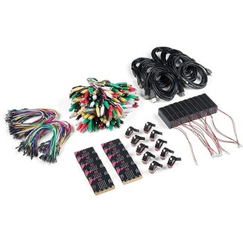 SparkFun Educator Lab Pack for micro:bit v2SPARKFUN
¥109,800税込¥120,780
1個
33日以内出荷
DescriptionThe micro:bit v2 Educator's Lab Pack includes 10 micro:bit v2 boards and everything you need to get you started with the new learning platform. The Lab Pack has everything you need, including micro:bits, cables, battery packs and a few parts to experiment with. This package provides an easy way to introduce your students to the micro:bit without any difficulty or parts hunting.SparkFun packages everything educators need to get started with the micro:bit in a variety of classroom settings and learning environments. The hardware boards, cables and extra parts come pre-packaged. Examples and curriculum materials are available from SparkFun and micro:bit, as well as from other educators involved in this growing maker education movement.Lab Packs are your classroom entry point. By combining our kits, popular boards and other educational tools with support materials(to be updated), SparkFun brings all the power of the open source community to the classroom. We've also updated the battery pack to be closer to what is in other micro:bit kits. It now requires 2xAAA batteries.The micro:bit is a pocket-sized computer that lets you get creative with digital technology. Between the micro:bit and our shield-like bit boards you can do almost anything while coding, customizing and controlling your micro:bit from almost anywhere! You can use your micro:bit for all sorts of unique creations, from robots to musical instruments and more. At half the size of a credit card, this versatile board has vast potential!FeaturesMicro:bit 2.0:64 MHz Arm Cortex-M4 with FPU512KB Flash128KB RAM5x5 Red LED ArrayTwo Programmable Buttons, one touch sensitive logoMEMS microphone and LED indicatorOnboard Light, Compass, Accelerometer, Temp Sensors and Speaker2.4 Ghz Micro:bit Radio/BLE 5.0 Smart Antenna25-pin Edge Connector4 dedicated GPIO, PWM, i2c, SPI, and ext. powerThree Digital/Analog Input/Output RingsTwo Power Rings --- 3V and GNDDedcated I2C bus for peripheralsMicroUSB Connector(5V)JST-PH Battery Connector(NotJST-XH)(3V)Power/reset Button with Status LED200 mA available for accessoriesProgram with C++, MakeCode, Python, Scratch
アズワン品番67-0424-92
 Alchitry Cu FPGA Development Board Lattice iCE40 HXSPARKFUN
¥15,980税込¥17,578
1個
33日以内出荷
DescriptionIf you are not needing a lot of power to start your FPGA adventure, or are looking for a more economical option, the Alchitry Cu FPGA Development Board might be the perfect option for you! The Alchitry Cu is a "lighter" FPGA version than the Alchitry Au but still offers something completely unique. FPGAs, or Field-Programmable Gate Arrays, are an advanced development board type for engineers and hobbyists alike to experience the next step in programming with electronics. The Cu truly exemplifies the trend of more affordable and increasingly powerful FPGA boards arriving each year. This board is a fantastic starting point into the world of FPGAs and the heart of your next project. Finally, now that this board is built by SparkFun, we added a Qwiic connector for easy I2C integration!The Alchitry Cu uses the Lattice iCE40 HX FPGA with 7680 logic cells and is supported by the open source tool chain Project IceStorm. The Cu possesses 79 IO pins with eight general purpose LEDs; a 100MHz on-board clock that can be manipulated internally by the FPGA; a USB-C connector to configure and power the board; and a USB to serial interface for data transfer.By adding stackable expansion boards similar to shields or HATs called "Elements," the Alchitry Cu is able to expand its own hardware capabilities by adding prototyping spaces, buttons, LEDs, and more!The SparkFun Qwiic Connect System is an ecosystem of I2C sensors, actuators, shields and cables that make prototyping faster and less prone to error. All Qwiic-enabled boards use a common 1mm pitch, 4-pin JST connector. This reduces the amount of required PCB space, and polarized connections mean you can't hook it up wrong.Get Started with our Learning FPGA TutorialsFeaturesLattice iCE40-HX8K FPGA - 7680 logic elements79 IO pins(3.3V logic level)USB-C to configure and power the boardEight general purpose LEDsOne button(typically used as a reset)100MHz on-board clock(can be multiplied internally by the FPGA)Powered with 5V through USB-C port, 0.1" holes, or headersUSB to serial interface for data transfer(up to 12Mbaud)Qwiic ConnectorDimensions of 65mm×45mmExamplesFirst FPGA Project - Getting Fancy with PWMExternal IO and Metastability
アズワン品番67-0423-08
 Standard PCB Drill Set 10 PiecesSPARKFUN
¥9,698税込¥10,668
1個
33日以内出荷
DescriptionThis is standard PCB Drill Set from Carbide 3D that supplies you with more options for drilling into copper clad on your Shapeoko or Nomad CNC machines. Each set includes three 0.5mm, five 0.7mm, and two 0.9mm PCB drills each with a 0.125"
アズワン品番67-0428-39
 SparkFun Thing Plus - RP2040SPARKFUN
¥6,698税込¥7,368
1個
33日以内出荷
DescriptionThe SparkFun Thing Plus - RP2040 is a low-cost, high performance board with flexible digital interfaces featuring the Raspberry Pi Foundation's RP2040 microcontroller. Besides the Thing Plus orFeatherfootprint(with 18 GPIO pins), the board also includes an SD card slot, 16MB(128Mbit)flash memory, a JST single cell battery connector(with a charging circuit and fuel gauge sensor), an addressable WS2812 RGB LED, JTAG PTH pins, four(4-40 screw)mounting holes, and our signature Qwiic connector.The RP2040 contains two ARM Cortex-M0+ processors(up to 133MHz)and features:264kB of embedded SRAM in six banks6 dedicated IO for SPI Flash(supporting XIP)30 multifunction GPIO:Dedicated hardware for commonly used peripheralsProgrammable IO for extended peripheral supportFour 12-bit ADC channels with internal temperature sensor(up to 0.5 MSa/s)USB 1.1 Host/Device functionalityThe RP2040 is supported with both C/C++ and MicroPython cross-platform development environments, including easy access to runtime debugging. It has UF2 boot and floating-point routines baked into the chip. While the chip has a large amount of internal RAM, the board includes an additional 16MB of external QSPI flash memory to store program code.The SparkFun Qwiic Connect System is an ecosystem of I2C sensors, actuators, shields and cables that make prototyping faster and less prone to error. All Qwiic-enabled boards use a common 1mm pitch, 4-pin JST connector. This reduces the amount of required PCB space, and polarized connections mean you can't hook it up wrong.Get Started With the Thing Plus RP2040 Hookup GuideFeaturesSparkFun Thing Plus - RP2040 FeaturesRaspberry Pi Foundation's RP2040 microcontroller16MB QSPI Flash MemoryJTAG PTH PinsThing Plus(or Feather)Form-Factor:18[1]x Multifunctional GPIO Pins[2]Four available 12-bit ADC channels with internal temperature sensor(500kSa/s)Up to eight 2-channel PWMUp to two UARTsUp to two I2C busesUp to two SPI busesUSB-C Connector:USB 1.1 Host/Device functionality2-pin JST Connector for a LiPo Battery(not included)500mA charging circuitQwiic ConnectorButtons:BootResetLEDs:PWR- Red 3.3V power indicatorCHG- Yellow battery charging indicator25- Blue status/test LED(GPIO 25)WS2812- Addressable RGB LED(GPIO 08)Four Mounting Holes:4-40 screw compatibleDimensions:2.3"×0.9"RP2040 General FeaturesDual Cortex M0+ processors, up to 133 MHz264 kB of embedded SRAM in 6 banks6 dedicated IO for QSPI flash, supporting execute in place(XIP)30 programmable IO for extended peripheral supportSWD interfaceTimer with 4 alarmsReal time counter(RTC)USB 1.1 Host/Device functionalitySupported programming languagesMicroPythonC/C++1.Note:GPIO 08is not included in this count, as it passes through the WS2812 addressable RGB LED first.GPIO 07andGPIO 23are counted as a single GPIO because they are tied together.2.Note:The GPIO pins are programmable so you can reconfigure the pins! Check out the RP2040 datasheet for more information on the GPIO functionality.
アズワン品番67-0423-56
 ESP32 Thing Stackable Header SetSPARKFUN
¥779税込¥857
1個
欠品中
DescriptionThese headers are made to work with the SparkFun ESP32 Thing to connect to ESP32 Shield boards. Each set of headers makes your ESP32 Thing easily stackable with the Power Control, Environmental, or Motion Shields as well as other applications. This set includes two 1x20 headers, enough to connect your ESP32 to anything you want!
アズワン品番67-0425-34
 SparkFun Level Translator Breakout - PCA9306SPARKFUN
¥1,498税込¥1,648
1個
33日以内出荷
DescriptionThere are a couple must-have boards that every engineer and hobbyist should have on their desk, and this PCA9306 dual, bidirectional voltage-level translator breakout is one of them! Because different parts sometimes use different voltage
アズワン品番67-0420-05
 SparkFun Environmental Sensor Breakout - BME680 QwiicSPARKFUN
¥8,498税込¥9,348
1個
欠品中
DescriptionThe SparkFun BME680 Environmental Sensor is a breakout that combines a gas sensor with temperature, humidity and barometric pressure sensing for a complete environmental sensor in a single package. The gas sensor on the BME680 can detect a
アズワン品番67-0427-22
 SparkFun MicroMod Asset Tracker Carrier BoardSPARKFUN
¥43,980税込¥48,378
1個
33日以内出荷
DescriptionNote - Please read before purchasing!:The MicroMod Asset Tracker uses the "00B" product version of the SARA-R5 module(specifically the SARA-R510M8S-00B-00). LTE NB-IoT Radio Access Technology, and the LTE FDD bands:66, 71, 85 are not suppor
アズワン品番67-0423-27
 SparkFun AST-CAN485 Dev BoardSPARKFUN
¥19,980税込¥21,978
1個
欠品中
DescriptionThe SparkFun AST-CAN485 Dev Board is a miniature Arduino in the compact form factor of the Pro Mini. In addition to all the usual features that a mini Arduino has, it possesses an onboard CAN(Control Area Network)and RS485 ports, enabling q
アズワン品番67-0422-53
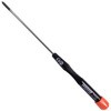
 Xcelite 8-in-1 Screwdriver SetSPARKFUN
¥8,998税込¥9,898
1個
33日以内出荷
DescriptionThe Xcelite 8-in-1 Screwdriver Set provides eight high-quality bits in a single ergonomic tool. Each bit is easily accessible with a spring-loaded magnetic housing that holds the seven included bits you aren't currently using. Though the screwdriver set includes eight unique bits, the end of the shaft features a 0.25" hex driver that can fit most of your existing 1/4" bits. With a strong magnetic hold and no-roll handle design, this is one of the best all-in-one tools we have used!The shaft of this multiple-tip driver is made from a chrome-molybdenum vanadium steel that makes for great durability and longevity.
アズワン品番67-0428-23
 Feather Stackable Header KitSPARKFUN
¥759税込¥835
1個
欠品中
DescriptionThese stackable headers are made to work with the SparkFun ESP32 Thing Plus to connect to shield with a Feather footprint. This set includes one 12-pin and one 16-pin header; the pins are spaced by 0.1".Each set of headers allows you to
アズワン品番67-0425-62
 Artech Digital Multimeter - A5020SPARKFUN
¥12,380税込¥13,618
1個
欠品中
DescriptionThe digital multimeter(DMM)is an essential tool in every electronic enthusiasts arsenal. This Smart Digital Multimeter, however, is not your average multimeter, it features a continuity sound at less than about 40±10Ω, current/voltage sense
アズワン品番67-0428-87
 Artech Digital Multimeter - A5030SPARKFUN
¥13,980税込¥15,378
1個
欠品中
DescriptionThe digital multimeter(DMM)is an essential tool in every electronic enthusiasts arsenal. This Smart Digital Multimeter, however, is not your average multimeter, it features a continuity sound at less than about 40±10Ω, current/voltage
アズワン品番67-0428-88
 Rotary Potentiometer - 100k Ohm, Logarithmic Panel MountSPARKFUN
¥949税込¥1,044
1個
欠品中
DescriptionAn adjustable potentiometer can open up many interesting user interfaces. With this rotary potentiometer just turn the dial and the resistance changes. This potentiometer from Bourns has a 1/4" metal knurled shaft diameter, PC pin terminal
アズワン品番67-0421-10
 LED RGB Strip - Addressable, Sealed, 1m APA104SPARKFUN
¥9,998税込¥10,998
1個
欠品中
DescriptionGone are the days that you have to worry about silicone weather proofing splitting and breaking on you! These are sealed addressable 1 meter long 5V RGB LED strips that come packed with 60 APA104s per meter. Each of these strips are enclosed by a flexible silicon jacket with an IP65 waterproof rating to protect your precious APA104 LEDs. You will be able to control each RGB LED individually giving you the ability to create cool lighting effects for your car, fish tank, or perhaps under cabinet lighting in your kitchen! These LED strips are compatible with similar WS2812 and SK6812 addressable LED's.Note:These come in 1m segments on a reel. They are preterminated with 0.1" spaced 3-pin connectors as well as a 2 wire power connector, as shown in the pictures.FeaturesFlexible LED strip with external control for each LED pixelHigh brightness, full-color and fully addressable(cascade, chasing and scanning)Maximum length of 5 metersExample uses include architectural, landscape, and decorative lighting
アズワン品番67-0421-40
 Slide Potentiometer Knob - Small and MediumSPARKFUN
¥399税込¥439
1個
33日以内出荷
DescriptionThis is a simple knob that connects to the small and medium sized linear slide potentiometers. Each knob uses friction to secure itself to fit onto the slide pot. Once attached, this small knob provides you with an easier to use potentiometer for your project!
アズワン品番67-0421-19
 心拍センサーSPARKFUN
¥9,898税込¥10,888
1個
33日以内出荷
DescriptionHeart rate data can be really useful whether you're designing an exercise routine, studying your activity or anxiety levels or just want your shirt to blink with your heart beat. The problem is that heart rate can be difficult to measure. L
アズワン品番67-0437-01
 Raspberry Pi PicoSPARKFUN
¥1,798税込¥1,978
1個
33日以内出荷
DescriptionThe Raspberry Pi Pico is a low-cost, high-performance microcontroller board with flexible digital interfaces. It feature the RP2040 which marks Raspberry Pi's first microcontroller designed in-house. Pico provides minimal(yet flexible)exter
アズワン品番67-0423-57

 Amphenol FCI Clincher Connector 2 Position, MaleSPARKFUN
¥1,098税込¥1,208
1個
欠品中
DescriptionThese Clincher connectors from Amphenol FCI can be used to terminate Flat Flexible Cables(FFCs)to an easy-to-use standard header. Simply insert the end of the cable into the connector and press it closed. The teeth inside the connector will
アズワン品番67-0351-04