カテゴリ
- 学童・教育用品(136)
- 制御機器(12)
絞り込み
ブランド
- SPARKFUN
- FUKUTOKU(福徳産業)(629)
- オカムラ(岡村製作所)(378)
- SMC(85)
- 三菱ふそう(84)
- ホンダ(83)
- BMW(31)
- Hutchinson(30)
- FMF(エフエムエフ)(25)
- Geometric Future(24)
- ルートート(16)
- brembo(14)
- ハウステック(14)
- MV AGUSTA(13)
- GPR Exhaust (ジーピーアールエキゾースト)(13)
- SIEMENS(12)
- BAGSTER (バグスター)(11)
- スイコー(10)
- 東芝(10)
- ブランドをもっと見る
「fut」の検索結果
 Raspberry Pi Zero CaseSPARKFUN
¥2,298税込¥2,528
1個
当日出荷
DescriptionThe Raspberry Pi Zero Case has been designed to fit both the Pi Zero and the Pi Zero W. These official cases consist of several parts and protect the Raspberry Pi Zero from things like rogue wires that might short it out while still allowing full access to the board. Simply snap the RPi into the bottom half of the enclosure, then snap on a desired top. No tools required!Each case has a standard base featuring a cut-out to allow access to the GPIO, and a choice of three lids:a standard lid, a GPIO lid(allowing access to the GPIO pins from above)and a camera lid(which, when used with the short camera cable supplied, allows the Raspberry Pi camera to be fitted neatly inside it). Additionally, each case includes a 4cm long CSI cable and four rubber feet.Note:This case doesNOTinclude a Raspberry Pi or Camera Module.
アズワン品番67-0425-31
 SparkFun Audio Jack BreakoutSPARKFUN
¥429税込¥472
1個
欠品中
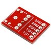
Audio Jack Breakoutは、3.5mmオーディオジャックを接続するための基板です。5本のピンを引き出してあるので、ここにピンヘッダをはんだ付けすればブレッドボードやプリント基板に接続することができます。
アズワン品番63-3035-60


 SparkFun LED Driver Breakout - LP55231SPARKFUN
¥3,500税込¥3,850
1個
7日以内出荷
DescriptionThe SparkFun LP55231 LED Driver Breakout is a self-contained solution for developing and deploying the nine-channel I2C LED controller. Remarkably simple, the breakout is equipped primarily with just the LP55231 LED controller IC, plus thr
アズワン品番67-0419-94

 SparkFun Triple Axis Accelerometer Breakout - LIS3DHSPARKFUN
¥2,198税込¥2,418
1個
7日以内出荷
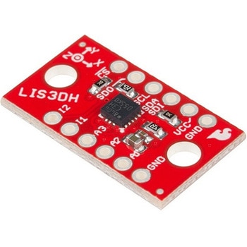
DescriptionThe LIS3DH Breakout is a smart, low-power, three-axis, capacitive micro-machined accelerometer with 12 bits of resolution that you can use to add translation detection to your project. It would be classified as a 3DoF, or 3 Degrees of Free
アズワン品番67-0426-60
 SparkFun Triple Axis Accelerometer Breakout - ADXL362SPARKFUN
¥6,998税込¥7,698
1個
7日以内出荷
仕様●シリーズ名:(汎用品)●種別:モジュール●主機能:センサー●シールドコネクタ:一般モジュール(基板)●主要チップ:ADXL362アズワン品番67-0455-39
 Thermocouple Connector - PCC-SMP-KSPARKFUN
¥3,798税込¥4,178
1個
9日以内出荷
DescriptionThis Thermocouple Connector is perfect for bridging the gap between Type-K thermocouples with standard connectors with a PCB. This little connector is actually the exact part we recommend using with our SparkFun Thermocouple Breakout! Each
アズワン品番67-0425-14
 ArduinoMega 2560 R3SPARKFUN
¥18,980税込¥20,878
1個
33日以内出荷
DescriptionArduino is an open-source physical computing platform based on a simple i/o board and a development environment that implements the Processing/Wiring language. Arduino can be used to develop stand-alone interactive objects or can be connected to software on your computer(e.g. Flash, Processing, MaxMSP). The open-source IDE can be downloaded for free(currently for Mac OS X, Windows, and Linux).The Arduino Mega is a microcontroller board based on the ATmega2560. It has 54 digital input/output pins(of which 14 can be used as PWM outputs), 16 analog inputs, 4 UARTs(hardware serial ports), a 16 MHz crystal oscillator, a USB connection, a power jack, an ICSP header, and a reset button. It contains everything needed to support the microcontroller; simply connect it to a computer with a USB cable or power it with a AC-to-DC adapter or battery to get started.Never fear for accidental electrical discharge, either since since the Mega also includes a plastic base plate to protect it!The Mega 2560 R3 also adds SDA and SCL pins next to the AREF.In addition, there are two new pins placed near the RESET pin. One is the IOREF that allow the shields to adapt to the voltage provided from the board.The other is a not connected and is reserved for future purposes.The Mega 2560 R3 works with all existing shields but can adapt to new shields which use these additional pins.Not sure which Arduino or Arduino-compatible board is right for you? Check out our Arduino Buying Guide!FeaturesATmega2560 microcontrollerInput voltage - 7-12V54 Digital I/O Pins(14 PWM outputs)16 Analog Inputs256k Flash Memory16Mhz Clock Speed
アズワン品番67-0349-13
 SparkFun GPS Breakout - NEO-M9N, SMA QwiicSPARKFUN
¥22,980税込¥25,278
1個
33日以内出荷
DescriptionThe SparkFun NEO-M9N GPS Breakout is a high quality GPS board with equally impressive configuration options including SMA. The NEO-M9N module is a 92-channel u-blox M9 engine GNSS receiver, meaning it can receive signals from the GPS, GLONASS, Galileo, and BeiDou constellations with ~1.5 meter accuracy. This breakout supports concurrent reception of four GNSS. This maximizes position accuracy in challenging conditions increasing, precision and decreases lock time; and thanks to the onboard rechargeable battery, you'll have backup power enabling the GPS to get a hot lock within seconds! Additionally, this u-blox receiver supports I2C(u-blox calls this Display Data Channel)which makes it perfect for the Qwiic compatibility so we don't have to use up our precious UART ports. Utilizing our handy Qwiic system, no soldering is required to connect it to the rest of your system. However, we still have broken out 0.1"-spaced pins in case you prefer to use a breadboard.The NEO-M9N module detects jamming and spoofing events and can report them to the host, so that the system can react to such events. A SAW(Surface Acoustic Wave)filter combined with an LNA(Low Noise Amplifier)in the RF path is integrated into the NEO-M9N module which allows normal operation even under strong RF interferences.U-blox based GPS products are configurable using the popular, but dense, windows program called u-center. Plenty of different functions can be configured on the NEO-M9N:baud rates, update rates, geofencing, spoofing detection, external interrupts, SBAS/D-GPS, etc. All of this can be done within the SparkFun Arduino Library!The SparkFun NEO-M9N GPS Breakout is also equipped with an on-board rechargeable battery that provides power to the RTC on the NEO-M9N. This reduces the time-to-first fix from a cold start(~24s)to a hot start(~2s). The battery will maintain RTC and GNSS orbit data without being connected to power for plenty of time.This product requires an antenna:Be sure to check out the related products/hookup accessories and pick a suitable SMA antenna for your project.The SparkFun Qwiic Connect System is an ecosystem of I2C sensors, actuators, shields and cables that make prototyping faster and less prone to error. All Qwiic-enabled boards use a common 1mm pitch, 4-pin JST connector. This reduces the amount of required PCB space, and polarized connections mean you can't hook it up wrong.The NEO-M9N GPS Breakout can also be automatically detected, scanned, configured, and logged using the OpenLog Artemis datalogger system. No programming, soldering, or setup required!Get Started With the SparkFun NEO-M9N GPS GuideFeaturesIntegrated SMA connector for use with antenna of your choice92-Channel GNSS Receiver1.5m Horizontal Accuracy25Hz Max Update Rate(four concurrent GNSS)Time-To-First-Fix:Cold:24sHot:2sMax Altitude:80,000mMax G:≦4Max Velocity:500m/sVelocity Accuracy:0.05m/sHeading Accuracy:0.3 degreesTime Pulse Accuracy:30ns3.3V VCC and I/OCurrent Consumption:~31mA Tracking GPS+GLONASSSoftware ConfigurableGeofencingOdometerSpoofing DetectionExternal InterruptPin ControlLow Power ModeMany others!Supports NMEA, UBX, and RTCM protocols over UART or I2C interfaces
アズワン品番67-0423-87

 Schmitt Trigger - CD40106BSPARKFUN
¥759税込¥835
1個
33日以内出荷
DescriptionThe CD40106BE consists of six Schmitt-trigger circuits. Each circuit functions as an inverter with Schmitt-trigger action on the input. The trigger switches at different points for positive- and negative-going signals. The difference between the positive-going voltage(VP)and the negative-going voltage(VN)is defined as hysteresis voltage(VH).FeaturesSchmitt trigger action with no external componentsHysteresis voltage typ. at 0.9V at VDD = 5V, 2.3V at VDD = 10V, and 3.5V at VDD = 15VNoise immunity greater than 50%No limit on input rise and fall timesStandardised, symmetrical output characteristics100% tested for quiescent current at 20sVMaximum input current of 1μA at 18 V over full package temperature range; 100nA at 18V and 25℃Low VDD to VSS current during slow input ramp
アズワン品番67-0420-89
 Raspberry Pi 7インチLCDタッチスクリーンSPARKFUN
¥35,980税込¥39,578
1セット
33日以内出荷
DescriptionThis 7" Raspberry Pi Touchscreen LCD provides you with the ability to create a standalone device that can be utilized as a custom tablet or an all-in-one interactive interface for a future project using your Raspberry Pi 3. Each LCD features a full color 800×480 capacitive touch display that connects to the Pi via an included adapter board which handles all of your power and signal conversion needs. An updated version of Raspbian OS on the A+, B+ and Pi2B is required for the display to work(the display does not work with the current version of Raspbian available on the Model A or B).What makes this LCD great is the fact that it only requires two connections to be hooked up to the Pi; power from the Pi's GPIO port and a ribbon cable that connects to the DSI port present on all Raspberry Pi's. Touchscreen drivers with support for 10-finger touch and an on-screen keyboard allow you to use your Raspberry Pi without an external keyboard or mouse.With this Raspberry Pi LCD you can create your own 'Internet of Things'(IoT)devices including a visual display by simply connecting your Pi, developing a easy Python script to interact with the display, and you'll be ready to create your own home automation devices with touch screen capability.Note:The latest version of Raspbian OS is required for this Raspberry Pi LCD to operate correctly.Features7" Touchscreen Display.Screen Dimensions:194mm×110mm×20mm(including standoffs)Viewable screen size:155mm×86mm70 degree viewing angleScreen Resolution 800×480 pixels @ 60fps24-bit color10 finger capacitive touch.Connects to the Raspberry Pi board using a ribbon cable connected to the DSI port.Adapter board is used to power the display and convert the parallel signals from the display to the serial(DSI)port on the Raspberry Pi.
アズワン品番67-0457-43
 SparkFun Auto pHAT for Raspberry PiSPARKFUN
¥12,980税込¥14,278
1個
33日以内出荷
DescriptionThe SparkFun Auto pHAT for Raspberry Pi is an all in one robotics package that focuses on quickly adding robot functionality and support to your Raspberry Pi or other single-board computer. The Auto pHAT can drive two small DC motors with o
アズワン品番67-0426-35


 SparkFun SAMD21 Dev BreakoutSPARKFUN
¥9,798税込¥10,778
1個
33日以内出荷
DescriptionIf you're ready to step your Arduino game up from older 8-bit/16MHz microcontrollers, the SparkFun SAMD21 Dev Breakout is a great landing spot. The SparkFun SAMD21 Dev Breakout is an Arduino-sized breakout for the Atmel ATSAMD21G18, a 32-bi
アズワン品番67-0422-19
 SparkFun RJ11 BreakoutSPARKFUN
¥829税込¥912
1個
33日以内出荷
DescriptionThis is the SparkFun RJ11 Breakout, two simple breakout boards for the common 6-pin RJ11 connector. These little boards can easily have one of our RJ11 6-Pin Connectors to work with common telephone cables. Each board features standard B/R/Y/G(Black/Red/Yellow/Green)labels on the top of the board to match a standard telephone wire. Additionally, each board has pin numbers on the back side that match with the pins on the connector.Each breakout consists of two boards -- one for each end of the connections -- as well as mounting holes to help you secure your project in place.
アズワン品番67-0420-01
 SparkFun Qwiic Button - Green LEDSPARKFUN
¥1,698税込¥1,868
1個
33日以内出荷
DescriptionButtons are an easy and tactile way to interface with your project, but why would you want to deal with debouncing, polling, and wiring up pull-up resistors? The Qwiic Button with built-in green LED simplifies all of those nasty worries away into an easy to use I2C device! Utilizing our Qwiic Connect System, using the button is as simple as connecting cable and loading up some pre-written code!If you need multiple buttons for your project, fear not! Each button has configurable I2C address, so you can daisy-chain multiple buttons over Qwiic and still address each one individually. We've got an example in our Arduino library that provides super-easy way to configure your Qwiic Button to whatever I2C address you desire. You can download the library through the Arduino library manager by searching 'SparkFun Qwiic Button' or you can get the GitHub repo as .zip file and install the library from there.In addition to handling blinking and debouncing, the Qwiic Button has configurable interrupts that can be configured to activate upon button press or click. We've also taken the liberty of implementing FIFO queue onboard the Qwiic Button where it keeps an internal record of when the button was pressed. This means that code on your microcontroller need not waste valuable processing time checking the status of the button but instead can run small function whenever the button is pressed or clicked! For more information on interrupts check out our guide here!The SparkFun Qwiic Connect System is an ecosystem of I2C sensors, actuators, shields and cables that make prototyping faster and less prone to error. All Qwiic-enabled boards use common 1mm pitch, 4-pin JST connector. This reduces the amount of required PCB space, and polarized connections mean you can't hook it up wrong.Get Started with the SparkFun Qwiic Button GuideFeatures12mm Green LED Button rated for 50mABuilt in LED can be configured for your desired level of blinkiness!Each button has configurable I2C addressConfigurable interrupts check out our guide here!FIFO queueDon't like the color green? Check out the SparkFun Qwiic Button Breakout and add another colored button!Red LED Tactile ButtonBlue LED Tactile ButtonGreen LED Tactile ButtonWhite LED Tactile Button
アズワン品番67-0420-14
 SparkFun 16 Output I/O Expander Breakout - SX1509SPARKFUN
¥2,198税込¥2,418
1個
33日以内出荷
DescriptionAre you low on I/O? No problem! The SX1509 Breakout is 16-channel GPIO expander with an I2C interface that means with just two wires, your microcontroller can interface with 16 fully configurable digital input/output pins. But the SX1509 can do so much more than just simple digital pin control. It can produce PWM signals, so you can dim LEDs. It can be set to blink or even breathe pins at varying rates. This breakout is similar to multiplexer or "mux," in that it allows you to get more IO from less pins. And, with built-in keypad engine, it can interface with up to 64 buttons set up in an 8x8 matrix.Two headers at the top and bottom of the breakout board function as the input and control headers to the board. This is where you can supply power to the SX1509, and where your I2C signals SDA and SCL will terminate. GPIO and power buses are broken out in every-which direction, and configurable jumpers cover most of the rest of the board.Since the I/O banks can operate between 1.2V and 3.6V(5.5V tolerant)independent of both the core and each other, this device can also work as level-shifter. The SX1509 breakout makes it easy to prototype so you can add more I/O onto your Arduino or I/O limited controller. We've even spun up an Arduino Library to get you started!FeaturesEnable Direct Level Shifting Between I/O Banks and Host Controller5.5V Tolerant I/Os, Up to 15mA Output Sink on All I/OsIntegrated LED Driver with Intensity ControlOn-Chip Keypad Scanning Engine Supports Up to 8x8 Matrix(64 Keys)16 Channels of True Bi-directional Style I/O400kHz I2C Compatible Slave Interface
アズワン品番67-0419-88

 SparkFun USB UART Serial Breakout - CY7C65213SPARKFUN
¥5,498税込¥6,048
1個
33日以内出荷
DescriptionThe CY7C65213 USB to UART serial breakout is designed to provide users with a means to access all available I/O pins on the IC, and to provide a 6-pin UART header that is compatible with other SparkFun breakout boards. This breakout has a m
アズワン品番67-0419-92
 SparkFun FT231X BreakoutSPARKFUN
¥4,598税込¥5,058
1個
33日以内出荷
DescriptionIntroducing the SparkFun FT231X Breakout board, complete with the full UART hardware handshake feature! The pin-out of this board matches the FTDI cable to work with official Arduino and cloned Arduino boards. It can also be used for general serial applications.This board still brings out the DTR pin as opposed to the RTS pin of the FTDI cable. The DTR pin allows an Arduino target to auto-reset when a new Sketch is downloaded. This is a really nice feature to have and allows a sketch to be downloaded without having to hit the reset button. This board will auto-reset any Arduino board that has the reset pin brought out to a 6-pin connector.The coolest thing about the FT231X Breakout is that we have broken out ALL the pins for your use, making this board all the more hackable! It also uses a common microUSB jack.One of the features of this board is a jumper on the back, which allows the VCC output to be configured to either 3.3V or 5V. This board ships default to 5V, but you can cut the default trace and add a solder jumper if you need to switch to 3.3V. It should be noted that the max input of the FT231X is only 3.3V, but it can operate down to 1.8V with external pull-ups and is also 5V tolerant.
アズワン品番67-0419-85
 SparkFun RFM69 Breakout 434MHzSPARKFUN
¥4,398税込¥4,838
1個
33日以内出荷
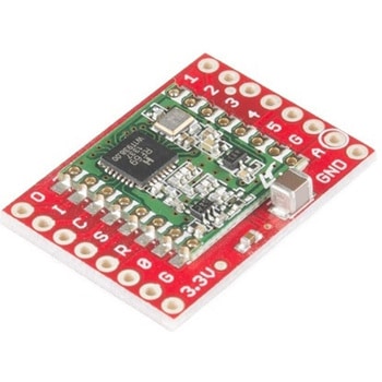
DescriptionThis is the SparkFun RFM69 Breakout, a small piece of tech that breaks out all the pins available on the RFM69HCW module as well as making the transceiver easy to use. The RFM69HCW is an inexpensive and versatile radio module that operates in the unlicensed ISM(Industry, Science and Medicine)radio band. It's perfect for building inexpensive short-range wireless networks of sensors and actuators for home automation, citizen science and more.This RFM69HCW operates on the 434MHz frequency and is capable of transmitting at up to 100mW and up to 300kbps, but you can change both of those values to fit your application. For example, you can maximize range by increasing the transmit power and reducing the data rate, or you can reduce both for short-range sensor networks that sip battery power. At full power and with simple wire antennas, we can get messages from one side of a large office building to the other through numerous internal walls. In open air you can reach 500 meters or more. With more complex antennas and modulation schemes, similar parts have successfully transmitted from space to the ground(by very smart amateur radio enthusiasts; your mileage may vary)!The RFM69HCW uses an SPI(Serial Peripheral Interface)to communicate with a host microcontroller, and several good Arduino libraries are available. It supports up to 256 networks of 255 nodes per network, features AES encryption to keep your data private, and transmits data packets up to 66 bytes long.SparkFun sells two versions of the RFM69HCW:a 915MHz version and this 434MHz version. Although the ISM band is license-free, the band itself is different in different areas. Very roughly, 915MHz is for use in the Americas, and the 434MHz version is for use in Europe, Asia and Africa. Check your local regulations for other areas.Get Started with the RFM69HCW Hookup GuideFeaturesTransmit power:-18dBm(0.016mW)to +20dBm(100mW)in 1dBm stepsReceive sensitivity:down to -120dBm at 1.2kbpsModulation types:FSK GFSK MSK GMSK OOKBit rates(FSK):1.2kbps to 300kbpsVoltage range:1.8V to 3.6VCurrent consumption:0.1uA sleep, 1.25mA standby, 16mA receive, 130mA transmit(max)Encryption:AES 128-bit(optional)Packet buffer(FIFO):66 bytes0.8"×1.1"
アズワン品番67-0429-33
 SparkFun GPS Breakout - XA1110 QwiicSPARKFUN
¥11,980税込¥13,178
1個
33日以内出荷
DescriptionThe SparkFun XA1110 GPS Breakout is a small I2C-supported module built for easy hookup, thanks to our Qwiic Connect System. Equipped with the XA1110 GPS module from GTOP, this board utilizes the MediaTek MT3333 chipset, loaded with speciali
アズワン品番67-0423-71
 SparkFun Cryptographic Co-Processor Breakout - ATECC508A QwiicSPARKFUN
¥2,698税込¥2,968
1個
欠品中
DescriptionThe SparkFun ATECC508A Cryptographic Co-Processor Breakout allows you to easily add strong authentication security to your IoT node, edge device, or embedded system. It includes two Qwiic ports for plug and play functionality. Utilizing ou
アズワン品番67-0422-83
 SparkFun HMC6343 BreakoutSPARKFUN
¥95,980税込¥105,578
1個
33日以内出荷
仕様●項目1:組込み(完成機能)●項目2:センサー●項目3:方位計●項目5:HMC6343アズワン品番67-0455-50
 SparkFun GPS Breakout - ZOE-M8Q QwiicSPARKFUN
¥14,980税込¥16,478
1個
33日以内出荷
DescriptionThe SparkFun ZOE-M8Q GPS Breakout is a high accuracy, miniaturized, GPS board that is perfect for applications that don't possess a lot of space. The on-board ZOE-M8Q is a 72-channel GNSS receiver, meaning it can receive signals from the GPS, GLONASS, BeiDou, and Galileo constellations. This increases precision and decreases lock time and thanks to the onboard rechargable battery you'll have backup power enabling the GPS to get a hot lock within seconds! Additionally, this u-blox receiver supports I2C(u-blox calls this Display Data Channel)which made it perfect for the Qwiic compatibility so we don't have to use up our precious UART ports. Utilizing our handy Qwiic system, no soldering is required to connect it to the rest of your system. However, we still have broken out 0.1"-spaced pins in case you prefer to use a breadboard.U-blox based GPS products are configurable using the popular, but dense, windows program called u-center. Plenty of different functions can be configured on the ZOE-M8Q:baud rates, update rates, geofencing, spoofing detection, external interrupts, SBAS/D-GPS, etc. All of this can be done within the SparkFun Arduino Library. We've also made sure to configure the UART pin grouping on the breakout to an industry standard to insure that it easily connects to a Serial Basic.The SparkFun ZOE-M8Q GPS Breakout is also equipped with an on-board rechargeable battery that provides power to the RTC on the ZOE-M8Q. This reduces the time-to-first fix from a cold start(~30s)to a hot start(~1s). The battery will maintain RTC and GNSS orbit data without being connected to power for up to five hours. Since the ZOE-M8Q is a tiny GPS receiver and to minimize its footprint, we've added a U.FL connector to allow the use of both large standard ceramic antennas as well as very small chip scale antennas.Note:The I2C address of the ZOE-M8Q is 0x42 and is software configurable. A multiplexer/Mux is required to communicate to multiple ZOE-M8Q sensors on a single bus. If you need to use more than one ZOE-M8Q sensor consider using the Qwiic Mux Breakout.The SparkFun Qwiic Connect System is an ecosystem of I2C sensors, actuators, shields and cables that make prototyping faster and less prone to error. All Qwiic-enabled boards use a common 1mm pitch, 4-pin JST connector. This reduces the amount of required PCB space, and polarized connections mean you can't hook it up wrong.The ZOE-M8Q GPS Breakout can also be automatically detected, scanned, configured, and logged using the OpenLog Artemis datalogger system. No programming, soldering, or setup required!Get Started With the SparkFun ZOE-M8Q Hookup GuideFeatures72-Channel GNSS Receiver2.5m Horizontal Accuracy18Hz Max Update RateTime-To-First-Fix:Cold:26sHot:1sMax Altitude:50,000mMax G:≦4Max Velocity:500m/sVelocity Accuracy:0.05m/sHeading Accuracy:0.3 degreesTime Pulse Accuracy:30ns3.3V VCC and I/OCurrent Consumption:~29mA Tracking GPS+GLONASSSoftware ConfigurableGeofencingOdometerSpoofing DetectionExternal InterruptPin ControlLow Power ModeMany others!Supports NMEA, UBX, and RTCM protocols over UART or I2C interfaces
アズワン品番67-0423-76
 SparkFun RFM69 Breakout 915MHzSPARKFUN
¥4,498税込¥4,948
1個
33日以内出荷
DescriptionThis is the SparkFun RFM69 Breakout, a small piece of tech that breaks out all the pins available on the RFM69HCW module as well as making the transceiver easy to use. The RFM69HCW is an inexpensive and versatile radio module that operates
アズワン品番67-0429-32
 SparkFun PIR Breakout - 170uA EKMC4607112KSPARKFUN
¥5,498税込¥6,048
1個
33日以内出荷
DescriptionPassive Infrared(PIR)sensors are great for detecting motion in a small area around the sensor. The 170μA SparkFun EKMC4607112K PIR Breakout is a simple board equipped with an EKM-series PIR sensor from Panasonic(R). The EKM-series PIR sensors are optimized for small movements to offer motion-sensing options for continuously powered applications.PIR sensors do not return specific distance data but instead monitor for IR light coming from objects in their field of view and will activate their signal when motion is detected in their sensing area, making them perfect for applications such as turning devices on automatically when motion is detected. Applications include home and building automation for energy saving, automated on/off lighting control, security, appliances, and IoT.Panasonic's low-profile PIR motion sensors(10.9mm versus standard 14.4mm height offer space savings for constrained designs)consist of a lens to create various detection zones, an optical filter to block non-infrared light, pyroelectric sensing elements, electromagnetic shielding to all circuitry, and an impedance converter to get an electrical signal. This PIR sensor offers digital output across 32 zones at 5m detection distance with 90°×90° detection area.Note:The sensitivity of passive infrared sensors is influenced by environmental conditions, so a performance evaluation test under representative conditions is recommended.Get Started with the SparkFun PIR Breakout GuideFeaturesOperating Voltage:2.3-4.0V170 μAstandby current consumptionLens diameter - 10.4mmLens Height - 10.9mm5m detection distance90°×90°(±45°)detection area
アズワン品番67-0427-43
 SparkFun I2C DAC Breakout - MCP4725SPARKFUN
¥2,098税込¥2,308
1個
33日以内出荷
仕様●項目1:組込み(完成機能)●項目2:AD、DA変換●項目4:DA変換●項目5:MCP4725アズワン品番67-0452-42
 SparkFun GPS Breakout - Chip Antenna, SAM-M8Q QwiicSPARKFUN
¥12,980税込¥14,278
1個
33日以内出荷
DescriptionThe SparkFun SAM-M8Q GPS Breakout is a high quality GPS board with equally impressive configuration options. The SAM-M8Q is a 72-channel GNSS receiver, meaning it can receive signals from the GPS, GLONASS, and Galileo constellations. This i
アズワン品番67-0423-77

 SparkFun GPS Breakout - NEO-M9N, Chip Antenna QwiicSPARKFUN
¥22,980税込¥25,278
1個
33日以内出荷
DescriptionThe SparkFun NEO-M9N GPS Breakout with on-board chip antenna is a high quality GPS board with equally impressive configuration options. The NEO-M9N module is a 92-channel u-blox M9 engine GNSS receiver, meaning it can receive signals from t
アズワン品番67-0423-81
 SparkFun TFT LCD Breakout - 1.8" 128x160SPARKFUN
¥9,998税込¥10,998
1個
33日以内出荷
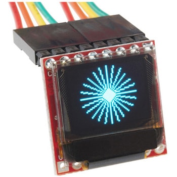
DescriptionThe SparkFun TFT LCD Breakout is a versatile, colorful, and easy way to experiment with graphics or create a user interface for your project. With a 4-wire SPI interface and microSD card holder, you can use this breakout to easily add visual display/interface capabilities to a project as well as providing all the storage you might need for multimedia files.To get started with this breakout, you will need an Arduino compatible microcontroller of your choice - we recommend something with extra RAM like the SparkFun Thing Plus. The breakout can be powered with either 5V or 3.3V. The microSD card holder is connected to the same SPI bus as the display which keeps the required pin count low and exists to relieve the burden from your microcontroller's poor memory due to having to store hundreds of images of cats, or really whatever you want to keep there. We have also gone ahead and tricked out the SparkFun HyperDisplay library with a driver made especially for this breakout!Out of the box, the SparkFun TFT LCD Breakout will come with a large backing PCB that makes it easy to securely mount the display in a project. If you need a more flexible solution you can remove the display module, snap off half the backing board, and then re-insert the display module. When this is done you'll be left with the bare minimum frame around the display to more seamLessly integrate with your project.Get Started With the SparkFun TFT LCD Breakout GuideFeatures128×160 RGB pixelsUp to 18 bit configurable color depth2x PWM controllabele LED backlightmicroSD Card SlotV-Score for Minimal Footprint Setup
アズワン品番67-0424-97
 SparkFun Qwiic Keypad - 12 ButtonSPARKFUN
¥4,198税込¥4,618
1個
33日以内出荷
DescriptionKeypads are very handy input devices, but who wants to tie up seven GPIO pins, wire up handful of pull-up resistors, and write firmware that wastes valuable processing time scanning the keys for inputs? The SparkFun Qwiic Keypad comes fully assembled and makes the development process for adding 12 button keypad easy. No voltage translation or figuring out which I2C pin is SDA or SCL, just plug and go! Utilizing our handy Qwiic system, no soldering is required to connect it to the rest of your system. However, we still have broken out 0.1"-spaced pins in case you prefer to use breadboard.Each of the keypad's 12 buttons has been labeled 1, 2, 3, 4, 5, 6, 7, 8, 9, 0, *, and and has been formatted to into the same layout as telephone keypad with each keypress resistance ranging between 10 and 150 Ohms. The Qwiic Keypad reads and stores the last 15 button presses in First-In, First-Out(FIFO)stack, so you don't need to constantly poll the keypad from your microcontroller. This information, then, is accessible through the Qwiic interface. The SparkFun Qwiic Keypad even has software configurable I2C address so you can have multiple I2C devices on the same bus.NOTE:The I2C address of the Qwiic Keypad is 0x4B and is jumper selectable to 0x4A(software-configurable to any address). multiplexer/Mux is required to communicate to multiple Qwiic Keypad sensors on single bus. If you need to use more than one Qwiic Keypad sensor consider using the Qwiic Mux Breakout.The SparkFun Qwiic connect system is an ecosystem of I2C sensors, actuators, shields and cables that make prototyping faster and less prone to error. All Qwiic-enabled boards use common 1mm pitch, 4-pin JST connector. This reduces the amount of required PCB space, and polarized connections mean you can't hook it up wrong.Get Started with the SparkFun Qwiic Keypad Hookup GuideFeaturesSoftware Selectable Slave AddressLow Power ATtiny85 controllerButton Presses w/ Time StampDefault I2C Address:0x4B2x Qwiic Connector
アズワン品番67-0421-41
 SparkFun Opto-isolator BreakoutSPARKFUN
¥1,998税込¥2,198
1個
33日以内出荷
仕様●項目1:組込み(完成機能)●項目2:インターフェース●項目4:アイソレータ(光)アズワン品番67-0452-28