カテゴリ
- 学童・教育用品(68)
- 制御機器(1)
- 空調・電設資材(1)
絞り込み
ブランド
- SPARKFUN
- ホンダ(233)
- RS PRO(120)
- 三菱ふそう(99)
- BMW(60)
- piaggio(ピアッジオグループ)(34)
- KTM(32)
- Triumph(30)
- メディアカバーマーケット(29)
- 長谷川工業(27)
- HASCO(24)
- GPR Exhaust (ジーピーアールエキゾースト)(24)
- FUNAHASHI(20)
- AMPHENOL(18)
- VISHAY(16)
- SKF(日本エスケイエフ)(13)
- KOA(11)
- DUCATI(11)
- AOHI(アオハイ)(11)
- ブランドをもっと見る
「has 12」の検索結果
 SparkFun Qwiic Keypad - 12 ButtonSPARKFUN
¥4,198税込¥4,618
1個
33日以内出荷
DescriptionKeypads are very handy input devices, but who wants to tie up seven GPIO pins, wire up handful of pull-up resistors, and write firmware that wastes valuable processing time scanning the keys for inputs? The SparkFun Qwiic Keypad comes fully assembled and makes the development process for adding 12 button keypad easy. No voltage translation or figuring out which I2C pin is SDA or SCL, just plug and go! Utilizing our handy Qwiic system, no soldering is required to connect it to the rest of your system. However, we still have broken out 0.1"-spaced pins in case you prefer to use breadboard.Each of the keypad's 12 buttons has been labeled 1, 2, 3, 4, 5, 6, 7, 8, 9, 0, *, and and has been formatted to into the same layout as telephone keypad with each keypress resistance ranging between 10 and 150 Ohms. The Qwiic Keypad reads and stores the last 15 button presses in First-In, First-Out(FIFO)stack, so you don't need to constantly poll the keypad from your microcontroller. This information, then, is accessible through the Qwiic interface. The SparkFun Qwiic Keypad even has software configurable I2C address so you can have multiple I2C devices on the same bus.NOTE:The I2C address of the Qwiic Keypad is 0x4B and is jumper selectable to 0x4A(software-configurable to any address). multiplexer/Mux is required to communicate to multiple Qwiic Keypad sensors on single bus. If you need to use more than one Qwiic Keypad sensor consider using the Qwiic Mux Breakout.The SparkFun Qwiic connect system is an ecosystem of I2C sensors, actuators, shields and cables that make prototyping faster and less prone to error. All Qwiic-enabled boards use common 1mm pitch, 4-pin JST connector. This reduces the amount of required PCB space, and polarized connections mean you can't hook it up wrong.Get Started with the SparkFun Qwiic Keypad Hookup GuideFeaturesSoftware Selectable Slave AddressLow Power ATtiny85 controllerButton Presses w/ Time StampDefault I2C Address:0x4B2x Qwiic Connector
アズワン品番67-0421-41
 SparkFun PCB Ruler - 12 InchSPARKFUN
¥3,198税込¥3,518
1個
欠品中
DescriptionOne ruler to rule them all. This is a basic 12 inch ruler, but made from a PCB. We have included a lots of useful information on each side of the ruler that you might use on a daily basis including Wire Gauge holes, transistor diagrams, common fractions, Roman numerals, and metric to imperial conversions. Most importantly, the ruler provides you with a straight line and centimeter markings one side and inch markings on the other side.You'll also find a small protractor in the middle for all your angle measurement needs. While we figured you have a fairly good idea how to use a ruler we do have a tutorial to explain all the information you'll see!Get Started with the How to use a Ruler GuideFeatures12 inch PCB ruler with markings down to 0.05" or 1/32"30.48 cm PCB ruler with markings down to 0.1mmElectrical Equations such as Ohm's Law and Parallel ResistorsKeyboard Alt CodesColor WavelengthsProtractorMetric Prefix Summary ChartMetric conversionsMorse CodeTransistor DiagramsRoman NumeralsFraction SummaryWire Guage ChartTap and Drill ChartSize:12"x 1.5"
アズワン品番67-0428-67
 QWIIC 12BIT 4CHANNEL ADS1015SPARKFUN
¥5,498税込¥6,048
1個
欠品中
DescriptionA lot of the time you just need to add more analog inputs to solve a problem. It happens. The SparkFun Qwiic 12 Bit ADC can provide four channels of I2C controlled ADC input to your Qwiic enabled project. These channels can be used as single-ended inputs, or in pairs for differential inputs. What makes this even more powerful is that it has a programmable gain amplifier that lets you "zoom in" on a very small change in analog voltage(but will still effect your input range and resolution). Utilizing our handy Qwiic system, no soldering is required to connect it to the rest of your system. However, we still have broken out 0.1"-spaced pins in case you prefer to use a breadboard.The ADS1015 uses its own internal voltage reference for measurements, but a ground and 3.3V reference are also available on the pin outs for users. This ADC board includes screw pin terminals on the four channels of input, allowing for solderless connection to voltage sources in your setup. It also has an address jumper that lets you choose one of four unique addresses(0x48, 0x49, 0x4A, 0x4B). With this, you can connect up to four of these on the same I2C bus and have sixteen channels of ADC. The maximum resolution of the converter is 12-bits in differential mode and 11-bits for single-ended inputs. Step sizes range from 125μV per count to 3mV per count depending on the full-scale range(FSR)setting.We have included an onboard 10K trimpot connected to channel A3. This is handy for initial setup testing and can be used as a simple variable input to your project. But don't worry, we added an isolation jumper so you can use channel A3 however you'd like.Note:The I2C address of the ADS1015 is 0x48 and is jumper selectable to 0x49, 0x4A, 0x4B. A multiplexer/Mux is required to communicate to multiple ADS1015 sensors on a single bus. If you need to use more than one ADS1015 sensor consider using the Qwiic Mux Breakout.The SparkFun Qwiic connect system is an ecosystem of I2C sensors, actuators, shields and cables that make prototyping faster and less prone to error. All Qwiic-enabled boards use a common 1mm pitch, 4-pin JST connector. This reduces the amount of required PCB space, and polarized connections mean you can't hook it up wrong.Get Started with the SparkFun Qwiic 12-Bit ADC Hookup GuideFeaturesADS1015Operating Voltage(VDD):2.0V-5.5V(Note:When powering with a Qwiic cable, the input range is only 3.3v)Operating Temperature:-40℃ to 125℃Operation Modes:Single-Shot, Continuous-Conversion(Default), and Duty CyclingAnalog Inputs:Measurement Type:Single-Ended(Default)Input Voltage Range:GND to VDDFull Scale Range(FSR):±.256V to ±6.114V(Default:2.048V)Resolution:12-bit(Differential)or 11-bit(Single-Ended)LSB size:0.125mV - 3mV(Default:1 mV)Sample Rate:128 Hz to 3.3 kHz(Default:1600SPS)Current Consumption(Typical):150μA-200μAI2C Address:0x48(Default), 0x49, 0x4A, or 0x4BScrew pin terminals for solderless connection to voltage sourcesFour unique I2C addresses:0x480x490x4A0x4B2x Qwiic connection portsOnboard 10K trimpot
アズワン品番67-0360-13
 Actuonix PQ12-100-6-R Micro-ActuatorSPARKFUN
¥47,980税込¥52,778
1個
欠品中
DescriptionThe PQ12 series of micro linear actuators are ideal for applications requiring precise positioning and compact size. Weighing in at just 22 grams, the PQ12 is incredibly light as well as compact. The affordably-priced PQ12 is the most powerful actuator of it's size. This is why it has become a popular choice for OEM manufacturers as well as Arduino and RC hobbyists. Some industries where the PQ12 are in use include:prosthetics, robotics, medical, simulation.The PQ12-R series of linear servos operate as a direct replacement for standard rotary servos. They use the same standard 3 wire connector, ground power and control. Regardless of how you drive your servos, be it with an RC receiver, an Arduino board, or a VEX micro-controller, the PQ12-R servo will function in place of a regular servo, but with the added benefit of providing linear motion. The PQ12-R is available in a 20mm stroke coupled with gear ratio options of 30:1, 63:1 and 100:1 cover a large variety of applications.The PQ12-100-6-R has:a 100:1 gear ratio for maximum lifting force; 6VDC operating voltage; and a servo(PWM)interface. This powerful little actuator can lift 50N(~5kg)!The datasheet doesn't mention a minimum operating voltage, but we've tested this actuator at 5VDC and it seems to work just fine. The maximum force and movement speed are reduced of course.FeaturesGearing Option:100:1Peak Power Point:40N @ 6mm/sPeak Efficiency Point:20N @ 8mm/sMax Speed(no load):10mm/sMax Force(lifted):50NMax Side Load:10NBack Drive Force:35NStroke:20 mmInput Voltage:6 VDCStall Current:550mA @ 6VMass:22gOperating Temperature -10℃ to +50℃Positional Repeatability:±0.1mmMechanical Backlash:0.25 mmAudible Noise:55dB @ 45cmIngress Protection:IP-54Maximum Duty Cycle:20%PWM(Servo)signal:Fully retracted:2.0ms @ 50HzFully extended:1.0ms @ 50Hz
アズワン品番67-0426-44
 Screw - Phillip Head M3×12mm, 3 packSPARKFUN
¥229税込¥252
1個
33日以内出荷
DescriptionThese are Philips-head M3 screws. They are 12mm long and come in packs of three. This is the screw size that the MiP robotic Platform and its add-on boards uses. Check below for the associated hardware.
アズワン品番67-0425-12
 Zrn Coated Flat Cutter - 0.0625in. Diameter, #112-Z 2 PackSPARKFUN
¥14,980税込¥16,478
1個
33日以内出荷
DescriptionThis flat mill is perfect for roughing or machining flat or primsatic parts. The cutter is coated with Ziconium Nitride,(ZrN).ZrN is a specialty coating that makes it exceptional for temperature sensitive materials. The coating has e
アズワン品番67-0428-62
 One-Wire Ambient Temperature Sensor - MAX31820SPARKFUN
¥1,598税込¥1,758
1個
33日以内出荷
DescriptionThe MAX31820 ambient temperature sensor provides 9-bit to 12-bit Celsius temperature measurements with ±0.5℃ accuracy over a +10℃ to +45℃ temperature range. Over its entire -55℃ to +125℃ operating range, the device has ±2.0℃ accuracy.The device communicates over a one-wire bus that, by definition, requires only one data line(and ground)for communication with a central microprocessor. In addition, the device can derive power directly from the data line, eliminating the need for an external power supply. Requiring so few pins enables the device to be placed in a 3-pin TO-92 package. The form factor of this package allows the device to be placed above the board and thus measure the ambient temperature of a system, as opposed to the board temperature that a surface-mount package would measure.Each MAX31820 has a unique 64-bit serial code, which allows multiple MAX31820 devices to function on the same one-wire bus. Therefore, it is simple to use one microprocessor to control many devices distributed over a large area.FeaturesUnique one-wire interface requires only one port pin for communicationEach device has a unique 64-bit serial code stored in onboard ROMMultidrop capability simplifies distributed temperature-sensing applicationsRequires no external componentsCan be powered from data line; 3.0V to 3.7V power-supply rangeMeasures temperatures from -55℃ to +125℃±0.5℃ accuracy from +10℃ to +45℃Thermometer resolution is user-selectable from 9 bits to 12 bitsConverts temperature to 12-bit digital word in 750ms(Max)User-definable nonvolatile(NV)alarm settingsAlarm search command identifies and addresses devices whose temperature is outside programmed limits(Temperature Alarm Condition)Available in 3-pin TO-92 packageTO-92 package allows measurement of ambient temperatureSoftware compatible with the DS1822 and DS18B20
アズワン品番67-0426-62
 Crystal 32kHzSPARKFUN
¥579税込¥637
1個
33日以内出荷
DescriptionStandard 'Watch' or Real-Time-Clock crystal. 32.768kHz means it is precisely half of a 16-bit counter. Start counting at 0x8000(or 32768). When the counter rolls over from 65535 to 0, then you know that exactly one second has passed. Reset the interrupt, reset the counter, and start counting again! Rated at 12.5pF load capacitance, 35K ohm max(18K ohm typical)series resistance, and +/- 20ppm stability. Small cylinder package.
アズワン品番67-0429-94
 SparkFun Qwiic Button - Green LEDSPARKFUN
¥1,698税込¥1,868
1個
33日以内出荷
DescriptionButtons are an easy and tactile way to interface with your project, but why would you want to deal with debouncing, polling, and wiring up pull-up resistors? The Qwiic Button with built-in green LED simplifies all of those nasty worries away into an easy to use I2C device! Utilizing our Qwiic Connect System, using the button is as simple as connecting cable and loading up some pre-written code!If you need multiple buttons for your project, fear not! Each button has configurable I2C address, so you can daisy-chain multiple buttons over Qwiic and still address each one individually. We've got an example in our Arduino library that provides super-easy way to configure your Qwiic Button to whatever I2C address you desire. You can download the library through the Arduino library manager by searching 'SparkFun Qwiic Button' or you can get the GitHub repo as .zip file and install the library from there.In addition to handling blinking and debouncing, the Qwiic Button has configurable interrupts that can be configured to activate upon button press or click. We've also taken the liberty of implementing FIFO queue onboard the Qwiic Button where it keeps an internal record of when the button was pressed. This means that code on your microcontroller need not waste valuable processing time checking the status of the button but instead can run small function whenever the button is pressed or clicked! For more information on interrupts check out our guide here!The SparkFun Qwiic Connect System is an ecosystem of I2C sensors, actuators, shields and cables that make prototyping faster and less prone to error. All Qwiic-enabled boards use common 1mm pitch, 4-pin JST connector. This reduces the amount of required PCB space, and polarized connections mean you can't hook it up wrong.Get Started with the SparkFun Qwiic Button GuideFeatures12mm Green LED Button rated for 50mABuilt in LED can be configured for your desired level of blinkiness!Each button has configurable I2C addressConfigurable interrupts check out our guide here!FIFO queueDon't like the color green? Check out the SparkFun Qwiic Button Breakout and add another colored button!Red LED Tactile ButtonBlue LED Tactile ButtonGreen LED Tactile ButtonWhite LED Tactile Button
アズワン品番67-0420-14
 SparkFun Atmospheric Sensor Breakout - BME280SPARKFUN
¥7,498税込¥8,248
1個
33日以内出荷
DescriptionThe SparkFun BME280 Atmospheric Sensor Breakout is the easy way to measure barometric pressure, humidity, and temperature readings all without taking up too much space. Basically, anything you need to know about atmospheric conditions you can find out from this tiny breakout. The BME280 Breakout has been design to be used in indoor/outdoor navigation, weather forecasting, home automation, and even personal health and wellness monitoring.The on-board BME280 sensor measures atmospheric pressure from 30kPa to 110kPa as well as relative humidity and temperature. The breakout provides a 3.3V SPI interface, a 5V tolerant I2C interface(with pull-up resistors to 3.3V), takes measurements at less than 1mA and idles less than 5μA. The BME280 Breakout board has 10 pins, but no more than six are used at a single time. The left side of the board provide power, ground, and I2C pins. The remaining pins which provide SPI functionality and have another power and ground, are broken out on the other side.Note:The breakout does NOT have headers installed and will need to purchased and soldered on yourself. Check theRecommended Productssection below for the type of headers we use in the Hookup Guide!FeaturesOperation Voltage:3.3VI2C SPI Communications InterfaceTemp Range:-40C to 85CHumidity Range:0 - 100% RH, =-3% from 20-80%Pressure Range:30,000Pa to 110,000Pa, relative accuracy of 12Pa, absolute accuracy of 100PaAltitude Range:0 to 30,000 ft(9.2 km), relative accuracy of 3.3 ft(1 m)at sea level, 6.6(2 m)at 30,000 ft.Incredibly Small
アズワン品番67-0426-57
 CO2 Humidity and Temperature Sensor - SCD30SPARKFUN
¥23,980税込¥26,378
1個
33日以内出荷
DescriptionThe SCD30 from Sensirion is a high quality Nondispersive Infrared(NDIR)based CO2 sensor capable of detecting 400 to 10000ppm with an accuracy of ±(30ppm+3%). In order to improve accuracy the SCD30 has temperature and humidity sensing built-in, as well as commands to set the current altitude. For additional accuracy the SCD30 also accepts ambient pressure readings!We've written an Arduino library to make reading the CO2, humidity, and temperature very easy. It can be downloaded through the Arduino Library manager:search for 'SparkFun SCD30' or it can be found in theDocumentstab above.The SCD30 Humidity and Temperature Sensor can also be automatically detected, scanned, configured, and logged using the OpenLog Artemis datalogger system. No programming, soldering, or setup required!Note:The SCD30 has an automatic self-calibration routine. Sensirion recommends 7 days of continuous readings with at least 1 hour a day of 'fresh air' for self-calibration to complete.FeaturesPower supply voltage:3.3V - 5.5VNDIR CO2 sensor technologyIntegrated temperature and humidity sensorBest performance-to-price ratioDual-channel detection for superior stabilitySmall form factor:35 mm×23 mm×7 mmMeasurement range:400 ppm - 10.000 ppmAccuracy:±(30 ppm + 3%)Current consumption:19 mA @ 1 meas. per 2 s.Energy consumption:120 mJ @ 1 measurementFully calibrated and linearizedDigital interface UART or I2C
アズワン品番67-0430-35
 TFMini Plus - Micro LiDAR ModuleSPARKFUN
¥28,980税込¥31,878
1個
欠品中
DescriptionThe TFMini Plus is a ToF(Time of Flight)LiDAR sensor capable of measuring the distance to an object as close as 10 centimeters(+/- 5cm up to 6m)and as far as 12 meters(+/-1% starting at 6m)! As with all LiDAR sensors, your effective detection distance will vary depending on lighting conditions and the reflectivity of your target object, but what makes this sensor special is its size. Measuring only 35x18.5x21mm, the TFMini Plus allows you to integrate LiDAR into applications traditionally reserved for smaller sensors.Setting itself apart from the original TFmini, the TFmini Plus has been designed with an IP65 enclosure meaning its "Dust tight water resistant", and also passed the vibration test of drone level, which will greatly expand its application range. The TFMini Plus is easy to power at only 5V and easy to talk to using the UART communication protocol.Important:This product does not use laser light for ranging. Instead it contains an LED and optics. Many such systems are being marketed under the name "LiDAR," although it may be more appropriate to think of this device as a "Time-of-Flight Infrared Rangefinder". It differs significantly from traditional IR rangefinders in that it uses ToF to determine range and not triangulation ― as is performed by the Sharp GP-series devices.FeaturesOperating Range - 0.1m~12m1Accuracy - ±5cm@(0.1-6m), ±1%@(6m-12m)Distance resolution - 5mmFrame rate - 1-1000Hz(adjustable)Ambient light immunity - 70kluxOperating temperature - -20℃~60℃Enclosure rating - IP65Light source - LEDCentral wavelength - 850nmFOV - 3.6°Supply voltage - 5V±0.5VAverage current - ≦110mAPower consumption - 550mWPeak current - 500mACommunication level - LVTTL(3.3V)Material of enclosure - ABS+PCStorage temperature - -20℃~75℃Weight - 11gWire length - 30cm
アズワン品番67-0426-94
 Bourns Absolute Encoder EAW0J-B24-AE0128LSPARKFUN
¥3,500税込¥3,850
1個
33日以内出荷
DescriptionThe Bourns Absolute Encoder is a digital control knob that provides 128 unique results evenly spaced around a full circle. It is designed as a control panel knob but can be adapted for other uses. This can be a good alternative to using a potentiometer and analog pin, as this allows for full-turn and multi-turn operation.It differs from the more common incremental rotary encoder which has only two or four values in a rotation and is designed to measure full rotations and direction. This measuresanglesand absolute position is maintained between power cycles.Features128 rotary positions360 degree continuous rotationRotational life - 50,000 revolutions(min)Max RPM - up to 120Absolute digital output will retain its last position between power cycles or in the event of a power failureThreaded M9x0.75 in. bushing3/4 in. rotating encoder shaftRear mount terminals
アズワン品番67-0421-27
 SparkFun Educator Lab Pack for micro:bit v2SPARKFUN
¥109,800税込¥120,780
1個
33日以内出荷
DescriptionThe micro:bit v2 Educator's Lab Pack includes 10 micro:bit v2 boards and everything you need to get you started with the new learning platform. The Lab Pack has everything you need, including micro:bits, cables, battery packs and a few parts to experiment with. This package provides an easy way to introduce your students to the micro:bit without any difficulty or parts hunting.SparkFun packages everything educators need to get started with the micro:bit in a variety of classroom settings and learning environments. The hardware boards, cables and extra parts come pre-packaged. Examples and curriculum materials are available from SparkFun and micro:bit, as well as from other educators involved in this growing maker education movement.Lab Packs are your classroom entry point. By combining our kits, popular boards and other educational tools with support materials(to be updated), SparkFun brings all the power of the open source community to the classroom. We've also updated the battery pack to be closer to what is in other micro:bit kits. It now requires 2xAAA batteries.The micro:bit is a pocket-sized computer that lets you get creative with digital technology. Between the micro:bit and our shield-like bit boards you can do almost anything while coding, customizing and controlling your micro:bit from almost anywhere! You can use your micro:bit for all sorts of unique creations, from robots to musical instruments and more. At half the size of a credit card, this versatile board has vast potential!FeaturesMicro:bit 2.0:64 MHz Arm Cortex-M4 with FPU512KB Flash128KB RAM5x5 Red LED ArrayTwo Programmable Buttons, one touch sensitive logoMEMS microphone and LED indicatorOnboard Light, Compass, Accelerometer, Temp Sensors and Speaker2.4 Ghz Micro:bit Radio/BLE 5.0 Smart Antenna25-pin Edge Connector4 dedicated GPIO, PWM, i2c, SPI, and ext. powerThree Digital/Analog Input/Output RingsTwo Power Rings --- 3V and GNDDedcated I2C bus for peripheralsMicroUSB Connector(5V)JST-PH Battery Connector(NotJST-XH)(3V)Power/reset Button with Status LED200 mA available for accessoriesProgram with C++, MakeCode, Python, Scratch
アズワン品番67-0424-92
 SparkFun Beefy 3 - FTDI Basic BreakoutSPARKFUN
¥5,798税込¥6,378
1個
33日以内出荷
DescriptionThis is SparkFun Beefy 3 FTDI Basic Breakout for the FTDI FT231X USB to serial IC. The pinout of this board matches the FTDI cable to work with official Arduino and cloned 3.3V Arduino boards. It can also be used for general serial applications. Built upon the same foundation as our 3.3V SparkFun FTDI Basic Breakout, the Beefy 3 is equipped with an AP2112K voltage regulator making this FTDI basic breakout board capable of handling a current load of up to 600 mA! With the addition of a more "Beefy" voltage regulator your will now be able to power a 3.3V project directly from the FTDI. The pinout of this board matches the FTDI cable to work with official Arduino and cloned 3.3V Arduino boards.This board brings out the DTR pin as opposed to the RTS pin of the FTDI cable. The DTR pin allows an Arduino target to auto-reset when a new Sketch is downloaded. This is a really nice feature to have and allows a sketch to be downloaded without having to hit the reset button. This board will auto reset any Arduino board that has the reset pin brought out to a 6-pin connector. The pins labeled BLK and GRN correspond to the colored wires on the FTDI cable. The black wire on the FTDI cable is GND, green is DTR. Use these BLK and GRN pins to align the FTDI basic board with your Arduino target.There are pros and cons to the FTDI Cable vs the FTDI Basic. This board has TX and RX LEDs that allow you to actually see serial traffic on the LEDs to verify if the board is working, however this board now requires a Micro-B USB cable. The FTDI Cable is well protected against the elements, but is large and cannot be embedded into a project as easily. The FTDI Basic uses DTR to cause a hardware reset where the FTDI cable uses the RTS signal.This board was designed to decrease the cost of Arduino development and increase ease of use(the auto-reset feature rocks!). Our Arduino Pro and LilyPad boards use this type of connector.
アズワン品番67-0430-06
 SparkFun Thing Plus - RP2040SPARKFUN
¥6,698税込¥7,368
1個
33日以内出荷
DescriptionThe SparkFun Thing Plus - RP2040 is a low-cost, high performance board with flexible digital interfaces featuring the Raspberry Pi Foundation's RP2040 microcontroller. Besides the Thing Plus orFeatherfootprint(with 18 GPIO pins), the board also includes an SD card slot, 16MB(128Mbit)flash memory, a JST single cell battery connector(with a charging circuit and fuel gauge sensor), an addressable WS2812 RGB LED, JTAG PTH pins, four(4-40 screw)mounting holes, and our signature Qwiic connector.The RP2040 contains two ARM Cortex-M0+ processors(up to 133MHz)and features:264kB of embedded SRAM in six banks6 dedicated IO for SPI Flash(supporting XIP)30 multifunction GPIO:Dedicated hardware for commonly used peripheralsProgrammable IO for extended peripheral supportFour 12-bit ADC channels with internal temperature sensor(up to 0.5 MSa/s)USB 1.1 Host/Device functionalityThe RP2040 is supported with both C/C++ and MicroPython cross-platform development environments, including easy access to runtime debugging. It has UF2 boot and floating-point routines baked into the chip. While the chip has a large amount of internal RAM, the board includes an additional 16MB of external QSPI flash memory to store program code.The SparkFun Qwiic Connect System is an ecosystem of I2C sensors, actuators, shields and cables that make prototyping faster and less prone to error. All Qwiic-enabled boards use a common 1mm pitch, 4-pin JST connector. This reduces the amount of required PCB space, and polarized connections mean you can't hook it up wrong.Get Started With the Thing Plus RP2040 Hookup GuideFeaturesSparkFun Thing Plus - RP2040 FeaturesRaspberry Pi Foundation's RP2040 microcontroller16MB QSPI Flash MemoryJTAG PTH PinsThing Plus(or Feather)Form-Factor:18[1]x Multifunctional GPIO Pins[2]Four available 12-bit ADC channels with internal temperature sensor(500kSa/s)Up to eight 2-channel PWMUp to two UARTsUp to two I2C busesUp to two SPI busesUSB-C Connector:USB 1.1 Host/Device functionality2-pin JST Connector for a LiPo Battery(not included)500mA charging circuitQwiic ConnectorButtons:BootResetLEDs:PWR- Red 3.3V power indicatorCHG- Yellow battery charging indicator25- Blue status/test LED(GPIO 25)WS2812- Addressable RGB LED(GPIO 08)Four Mounting Holes:4-40 screw compatibleDimensions:2.3"×0.9"RP2040 General FeaturesDual Cortex M0+ processors, up to 133 MHz264 kB of embedded SRAM in 6 banks6 dedicated IO for QSPI flash, supporting execute in place(XIP)30 programmable IO for extended peripheral supportSWD interfaceTimer with 4 alarmsReal time counter(RTC)USB 1.1 Host/Device functionalitySupported programming languagesMicroPythonC/C++1.Note:GPIO 08is not included in this count, as it passes through the WS2812 addressable RGB LED first.GPIO 07andGPIO 23are counted as a single GPIO because they are tied together.2.Note:The GPIO pins are programmable so you can reconfigure the pins! Check out the RP2040 datasheet for more information on the GPIO functionality.
アズワン品番67-0423-56
 ArduinoMega 2560 R3SPARKFUN
¥18,980税込¥20,878
1個
33日以内出荷
DescriptionArduino is an open-source physical computing platform based on a simple i/o board and a development environment that implements the Processing/Wiring language. Arduino can be used to develop stand-alone interactive objects or can be connected to software on your computer(e.g. Flash, Processing, MaxMSP). The open-source IDE can be downloaded for free(currently for Mac OS X, Windows, and Linux).The Arduino Mega is a microcontroller board based on the ATmega2560. It has 54 digital input/output pins(of which 14 can be used as PWM outputs), 16 analog inputs, 4 UARTs(hardware serial ports), a 16 MHz crystal oscillator, a USB connection, a power jack, an ICSP header, and a reset button. It contains everything needed to support the microcontroller; simply connect it to a computer with a USB cable or power it with a AC-to-DC adapter or battery to get started.Never fear for accidental electrical discharge, either since since the Mega also includes a plastic base plate to protect it!The Mega 2560 R3 also adds SDA and SCL pins next to the AREF.In addition, there are two new pins placed near the RESET pin. One is the IOREF that allow the shields to adapt to the voltage provided from the board.The other is a not connected and is reserved for future purposes.The Mega 2560 R3 works with all existing shields but can adapt to new shields which use these additional pins.Not sure which Arduino or Arduino-compatible board is right for you? Check out our Arduino Buying Guide!FeaturesATmega2560 microcontrollerInput voltage - 7-12V54 Digital I/O Pins(14 PWM outputs)16 Analog Inputs256k Flash Memory16Mhz Clock Speed
アズワン品番67-0349-13
 SparkFun Digital Temperature Sensor - TMP102 QwiicSPARKFUN
¥2,298税込¥2,528
1個
33日以内出荷
DescriptionWe all like to know the temperature, right? Well, with the SparkFun TMP102 Digital Temperature Sensor, we've made it just about as easy as it gets. Based on the original Digital Temperature Sensor Breakout TMP102, we've added Qwiic connectors to bring this board into our plug-and-play Qwiic Ecosystem and added an address jumper instead of breaking out the address pin. However, we still have broken out 0.1"-spaced pins in case you prefer to use breadboard.The TMP102 itself is an easy-to-use digital temperature sensor from Texas Instruments. While some temperature sensors use an analog voltage to represent the temperature, the TMP102 uses the I2C bus of the Arduino to communicate the temperature.The TMP102 is capable of reading temperatures to resolution of 0.0625℃, and is accurate up to 0.5℃. The breakout has built-in 4.7kΩ pull-up resistors for I2C communications and runs from 1.4V to 3.6V. I2C communication uses an open drain signaling, so there is no need to use level shifting.The SparkFun Qwiic Connect System is an ecosystem of I2C sensors, actuators, shields and cables that make prototyping faster and less prone to error. All Qwiic-enabled boards use common 1mm pitch, 4-pin JST connector. This reduces the amount of required PCB space, and polarized connections mean you can't hook it up wrong.Get Started with the Qwiic TMP102 Digital Temperature Sensor GuideFeaturesUses the I2C interfaceI2C Address:0x48 by default(Three additional addresses available, as well)12-bit, 0.0625℃ resolutionTypical temperature accuracy of ±0.5℃3.3V sensorSupports up to four TMP102 sensors on the I2C bus at time2x Qwiic Connectors
アズワン品番67-0427-17
 LIDAR-Lite v3HPSPARKFUN
¥39,980税込¥43,978
1個
33日以内出荷
DescriptionLIDAR has never looked so good! This is the LIDAR-Lite v3HP, a compact, high-performance optical distance measurement sensor from Garmin(TM). The LIDAR-Lite v3HP istheideal optical ranging solution for drone, robot, or unmanned vehicle applications. Each sensor is housed in a durable, IPX7-rated housing and includes all the core features and user configurability of the popular LIDAR-Lite v3.The v3HP is very similar in function to that of the v3 but it can now sample faster at rates greater than 1kHz(where as the v3 is only capable of up to 500Hz). Another improvement is that this v3HP model is more power efficient with current consumption rates 40mA less than the v3(that's 65mA as opposed to 105mA while idle, and 85mA instead of 130mA while acquiring).Each LIDAR-Lite v3HP has a range of 1m to 40m and features an edge-emitting, 905nm(1.3 watts), single-stripe laser transmitter, 8m Radian beam divergence, and an optical aperture of 12.5mm. This version of the LIDAR-Lite still operates at 5VDC(6V max)with a peak power of 1.3W and still possesses an accuracy of +/- 2.5cm at >2m. On top of everything else, the LIDAR-Lite is user-configurable, allowing adjustment between accuracy, operating range and measurement time and can be interfaced via I2C or PWM with the attached 200mm cable.Note:CLASS 1 LASER PRODUCT CLASSIFIED EN/IEC 60825-1 2014. This product is in conformity with performance standards for laser products under 21 CFR 1040, except with respect to those characteristics authorized by Variance Number FDA-2016-V-2943 effective September 27, 2016.Get Started with the LIDAR-Lite v3HP GuideFeaturesResolution:1 cmTypical accuracy:+/- 2.5cm at distances greater than 2 meters(Refer to operating manual for complete operating specifications)Range:1m to 40mUpdate rate:Greater than 1kHzInterface:I2C or PWMPower(operating voltage):4.75-5VDC; 6V MaxCurrent consumption:65ma idle; 85ma during acquisitionOperating temperature:-20℃ to 60℃Laser wave length/Peak power:905nm/1.3WBeam divergence:8m RadianOptical aperture:12.5mmWater rating:IPX7Unit dimensions:24.5mm×53.5mm×33.5mm(1.0in×2.1in×1.3in)Weight:34g(1.2oz)
アズワン品番67-0426-76
 Leopard Imaging Camera - 136 Degree FOVSPARKFUN
¥11,980税込¥13,178
1個
33日以内出荷
DescriptionThe Leopard Imaging Camera is a 136° FOV(field of view)wide angle camera module that is great for machine vision applications, and designed specifically to be compatible with the NVIDIA Jetson Nano Developer Kit. This camera incorporates a Sony IMX219 8.08MP color sensor, a fixed focus(M8)lens, and utilizes CSI-2 MIPI 2-lane data output interface.This is the same camera that we include in the SparkFun Jetbot v2.1 Kit.Note:SparkFun has not established the compatibility of this camera with Raspberry Pi. We are currently working with the manufacturer, but due to firmware restrictions Leopard cameras do not work with any Raspberry Pi's at this time.FeaturesField of view(FOV):136°Module size:150mm(L)x 25mm(W)Sensor type:Sony IMX219 8.08MP color sensorActive pixels:3280(H)x 2464(V)Image size:Diagonal 4.60mm(Type 1/4.0)F/No:2.0(H136)Focal length:1.58mm(H136)TV distortion:<-15%(H136)Focusing range:30cm - InfinityLens type:Fixed Focus(M8 lens)Pixel size:1.12um×1.12umData output interface:CSI-2 MIPI 2-laneIR Cutter Filter:Yes
アズワン品番67-0422-99
 Teensy Arduino Shield AdapterSPARKFUN
¥4,798税込¥5,278
1個
33日以内出荷
DescriptionThe Teensy is an amazing and compact development platform in breadboard friendly form factor, but what if you could incorporate it into the Arduino architecture? The Teensy Arduino Shield Adapter allows you to attach your Teensy and utilize your favorite Arduino shields without the requirement of breadboard or any complicated wiring. Needless to say, the Teensy Arduino Shield Adapter is useful tool for upgrading all of your existing Arduino projects to more powerful controller!As we stated before, the Teensy Arduino Shield Adapter provides basic Arduino compatibility with your run-of-the-mill shield but there are few other fun features that we've added on, as well. These features include Real Time Clock(RTC)battery, JST battery connector, 4-12V barrel jack connector, an ICSP header, and more. Because this board is simply an adapter, there is no special programming required to start working with the adapter. You will, however, need to program the Teensy for any Arduino shield you'd like to work with.While the adapter design can fit the Teensy LC footprint, it has been designed to fully utilize the features of the Teensy 3.1. Not all of the features available on the adapter are compatible with the LC so please be sure to check the Hookup Guide in theDocumentssection below to ensure functionality for your project. Please keep in mind that this adapter may be incompatible with some 5V Arduino shields. Please check our hookup guide for more information.Note:The Teensy Arduino Shield Adapter comes as kit and will need to be soldered together.Note:Due to the requirements of shipping the batteries in this kit, orders may take longer to process and therefore do not qualify for same-day shipping. Additionally, these batteries can not be shipped via Ground or Economy methods to Alaska or Hawaii. Sorry for any inconvenience this may cause.FeaturesArduino R3 InterfaceReal Time Clock BatteryJST Battery ConnectorBarrel JackI2C JumpersICSP HeaderDAC Pin Header
アズワン品番67-0424-36
 MI:pro Protector Case for micro:bit V2SPARKFUN
¥2,398税込¥2,638
1個
33日以内出荷
DescriptionThis MI:pro Protector Case for the BBC micro:bit has been designed to work with both the original micro:bit V1 and the micro:bit V2. These cases feature a four-layer construction style with ability to mount a 2xAAA battery pack to the back of the case while still providing access to all buttons and ports on the micro:bit. Though these cases do protect the micro:bit astoundingly well, the biggest benefit of using the MI:pro is to not accidentally short out the pads on the back of the micro:bit.Construction is simple, requiring only a small flathead screwdriver(at most), and involves layering each plate on top of one another around the micro:bit and screwing it into place. Luckily, the MI:pro Protector case enables easy access to the edge pins at the bottom of the micro:bit, allowing it to still be plugged into an edge connector found on many of our carrier boards. The only board that cannot be used in conjunction with the MI:pro case is the SparkFun gamer:bit due to its edge connector being located in the center of the board.Note:The MI:pro Protector case only includes the parts found in the Includes Tab. This case doesNOTinclude a micro:bit, power source or mounting screws. These items will need to be purchased separately.FeaturesDimensions:Length:65mm.Width:37mm.Depth(without screws):12mm.Depth(with screws):18.5mm.Provides excellent protection to the BBC micro:bit whilst allowing access to the bottom pins.Full access to the A and B buttons on the BBC micro:bit.Attach a battery cage to the rear of the case with the supplied sticky fixer.Full access to pins and connections including the micro USB connector.Clear case material shows the on-board LEDs in perfect clarity.The case is compatible with versions 1 and 2 of the micro:bit.When used in conjunction with a battery holder, micro:bit projects can be fully mobile.
アズワン品番67-0426-13
 SparkFun High Precision Temperature Sensor - TMP117 QwiicSPARKFUN
¥4,898税込¥5,388
1個
33日以内出荷
DescriptionThe SparkFun Qwiic TMP117 breakout is a high precision temperature sensor equipped with an I2C interface. It outputs temperature readings with high precision of ±0.1℃ across the temperature range of -20℃ to +50℃s with no calibration and a maximum range from -55℃ to 150℃. The SparkFun High Precision Temperature Sensor also has a very low power consumption rate which minimizes the impact of self-heating on measurement accuracy. Utilizing our handy Qwiic system, no soldering is required to connect it to the rest of your system. However, we still have broken out 0.1"-spaced pins in case you prefer to use a breadboard.The SparkFun High Precision Temperature Sensor also includes programmable temperature limits, and digital offset for system correction. While the TMP102 is capable of reading temperatures to a resolution of 0.0625℃ and is accurate up to 0.5℃, the on-board TMP117 is not only more precise but has a 16-bit resolution of 0.0078℃!To make this breakout even easier to use, we've written an Arduino library to help you get started "Qwiic-ly." Check the Documents tab above for more information.The SparkFun Qwiic Connect System is an ecosystem of I2C sensors, actuators, shields and cables that make prototyping faster and less prone to error. All Qwiic-enabled boards use a common 1mm pitch, 4-pin JST connector. This reduces the amount of required PCB space, and polarized connections mean you can't hook it up wrong.The TMP117 High Precision Temperature Sensor can also be automatically detected, scanned, configured, and logged using the OpenLog Artemis datalogger system. No programming, soldering, or setup required!Need a custom board? This component can be found in SparkFun's A La Carte board builder. You can have a custom design fabricated with this component - and your choice of hundreds of other sensors, actuators and wireless devices - delivered to you in just a few weeks.Get Started with the SparkFun High Precision TMP117 Hookup GuideFeaturesUses I2C interface(Qwiic-enabled)Four selectable addresses0x48(default), 0x49, 0x4A, 0x4B16-bit resolution, 0.0078℃High accuracy, digital temperature sensor±0.1℃(max)from ?20℃ to 50℃±0.15℃(max)from ?40℃ to 70℃±0.2℃(max)from ?40℃ to 100℃±0.25℃(max)from ?55℃ to 125℃±0.3℃(max)from ?55℃ to 150℃Operating temperature range-55℃ to +150℃Operating voltage range1.8V to 5.5VTypically 3.3V if using the Qwiic cableLow power consumption3.5μA(1-Hz conversion cycle)150nA(shutdown current)Programmable operating modesContinuous, one-shot, and shutdownProgrammable temperature alert limitsSelectable averaging for reduced noiseDigital offset for system correctionNIST traceabilityDocumentsSchematicEagle FilesBoard DimensionsHookup GuideDatasheet(TMP117)Arduino LibraryGitHub Hardware Repo
アズワン品番67-0427-10
 SparkFun Qwiic micro:bit BreakoutSPARKFUN
¥1,898税込¥2,088
1個
33日以内出荷
DescriptionThe SparkFun Qwiic micro:bit Breakout is a board that connects to the BBC micro:bit and expands the capabilities of the development platform by providing access to more pins and allowing for connections to the I2C and SPI buses. This breakout board for the micro:bit's edge connector allows intermediate and advanced users to connect the micro:bit to breadboards and other Qwiic sensors, motors, LEDs and more.The micro:bit on its own has three digital/analog input/output rings available for you to use initially with alligator clips. With the micro:bit Breakout we have broken out all 21 GPIO, power and ground-to-pin outs in a 0.1" formation and with two individual Qwiic Connectors. With this breakout you will be able to unlock the full potential of your micro:bit!Note:No micro:bit or headers are included with this breakout; they will need to be purchased separately. If you would like a micro:bit breakout with headers already soldered on, be sure to check out this board's sibling.The SparkFun Qwiic Connect System is an ecosystem of I2C sensors, actuators, shields and cables that make prototyping faster and less prone to error. All Qwiic-enabled boards use a common 1mm pitch, 4-pin JST connector. This reduces the amount of required PCB space, and polarized connections mean you can't hook it up wrong.Get Started with the Qwiic micro:bit Breakout Guide
アズワン品番67-0420-12
 XBee 3 Pro Module - U.FL AntennaSPARKFUN
¥12,980税込¥14,278
1個
33日以内出荷
DescriptionAfter years of popularity with the XBee Series 1 and XBee Series 2 Pro Modules, we now have the XBee Series 3 Pro which brings the best of both worlds. XBee 3 not only handles 802.15.4, and ZigBee, but also BLE protocols and you can now talk to the modules over UART or SPI as well. With a 300ft indoor range, or 2mile outdoor/line-of-sight range, you can set up a mesh network to talk to or communicate with various devices around your house, work, or other area.This module has the familiar XBee package while sporting a U.FL connector to add an antenna. You also get a built in microcontroller so you can also configure and program the modules using MicroPython as well as Digi's XCTU software. With a HCS08 CPU running at up to 50.33MHz, 15x digital I/O pins, and 4x 10-bit ADC pins these modules can even hold their own as a microcontroller.Note:While these are backwards compatible in many ways with the XBee 1s and 2s, they are not completely compatible. Please see documentation for differences if you plan on adding these to an existing project.FeaturesRF 250Kbps, Serial 1Mbps300ft(indoor)to 2 mile(outdoor)rangeTransmit power +19dBM @ 135mAReceiver Sensitivity -103dBm @ 15mA4x 10-bit ADC inputs15x Digital I/O pinsHCS08 CPU at up to 50.33MHz128/256 bit AES Encryption2.1V to 3.6V operating voltage1.7 μA power-down currentBuilt in RS-485 supportAT command or API frame supportFCC Certified
アズワン品番67-0429-52
 XBee 3 Pro Module - RP-SMA AntennaSPARKFUN
¥11,980税込¥13,178
1個
33日以内出荷
DescriptionAfter years of popularity with the XBee Series 1 and XBee Series 2 Pro Modules, we now have the XBee Series 3 Pro which brings the best of both worlds. XBee 3 not only handles 802.15.4, and ZigBee, but also BLE protocols and you can now talk to the modules over UART or SPI as well. With a 300ft indoor range, or 2mile outdoor/line-of-sight range, you can set up a mesh network to talk to or communicate with various devices around your house, work, or other area.This module has the familiar XBee package while sporting a connector to add an RP-SMA antenna. You also get a built in microcontroller so you can also configure and program the modules using MicroPython as well as Digi's XCTU software. With a HCS08 CPU running at up to 50.33MHz, 15x digital I/O pins, and 4x 10-bit ADC pins these modules can even hold their own as a microcontroller.Note:While these are backwards compatible in many ways with the XBee 1s and 2s, they are not completely compatible. Please see documentation for differences if you plan on adding these to an existing project.FeaturesRF 250Kbps, Serial 1Mbps300ft(indoor)to 2mile(outdoor)rangeTransmit power +19dBM @ 135mAReceiver Sensitivity -103dBm @ 15mA4x 10-bit ADC inputs15x Digital I/O pinsHCS08 CPU at up to 50.33MHz128/256 bit AES Encryption2.1V to 3.6V operating voltage1.7 μA power-down currentBuilt in RS-485 supportAT command or API frame supportFCC Certified
アズワン品番67-0429-54
 ATX Right Angle Connector - PTH 4-pinSPARKFUN
¥209税込¥230
1個
33日以内出荷
DescriptionThis 4-pin, ATX, right angle connector mates up to the standard 4-pin computer peripheral port often found on ATX power supplies. This connector will also serve as a replacement to that found in the SparkFun ATX Power Connector Breakout Kit.FeaturesWorks with 12V 5V devices.
アズワン品番67-0425-74
 SparkFun BabyBuck Regulator Breakout - 3.3V AP63203SPARKFUN
¥1,398税込¥1,538
1個
33日以内出荷
DescriptionWho doesn't occasionally need power regulation? We certainly do, so we've designed the SparkFun BabyBuck Regulator Breakout to help us with just such a task. Featuring the AP63203 from Diodes Inc, this breakout board takes advantage of a 2A synchronous buck converter that has a wide input voltage range of 3.8V to 32V and fully integrated 125mΩ high-side power MOSFET/68mΩ lowside power MOSFET to provide high-efficiency step-down DC/DC conversion. All of this snuggled up in a low-profile, TSOT26 package that's integrated into a 0.4in by 0.5in board.Unlike it's sibling, the BabyBuck sacrifices power option flexibility for space. Don't worry, though, because you can still use the plated through holes for input and output power. With some simple right-angle headers, you'll be up and running in no time.Frequency Spread Spectrum(FSS)reduces EMI and a proprietary gate driver scheme resists switching node ringing without sacrificing MOSFET turn-on and turn-off times, which further erases high-frequency radiated EMI noise.Get Started with the SparkFun Buck Regulator Hookup GuideFeaturesLow-Profile FootprintVIN 3.8V to 32VVOUT 3.3VUp to 2A Continuous Output Current0.8V ± 1% Reference Voltage22μA Ultralow Quiescent CurrentSwitching Frequency - 1.1MHzSupports Pulse Frequency Modulation(PFM)Up to 80% Efficiency at 1mA Light LoadUp to 88% Efficiency at 5mA Light LoadFixed Output Voltage - 3.3VProprietary Gate Driver Design for Best EMI ReductionFrequency Spread Spectrum(FSS)to Reduce EMIPrecision Enable Threshold to Adjust UVLOProtection CircuitryOvervoltage ProtectionCycle-by-Cycle Peak Current LimitThermal Shutdown
アズワン品番67-0421-86
 TFMini-S - Micro LiDAR ModuleSPARKFUN
¥23,980税込¥26,378
1個
欠品中
DescriptionThe TFMini-S Micro LiDAR Module is a ToF(Time of Flight)LiDAR sensor capable of measuring the distance to an object as close as 10 centimeters(+/- 6cm up to 6m)and as far as 12 meters(+/-1% starting at 6m)! As with all LiDAR sensors, your effective detection distance will vary depending on lighting conditions and the reflectivity of your target object, but what makes this sensor special is its size. Measuring only 42x15x16mm, the TFMini-S allows you to integrate LiDAR into applications traditionally reserved for smaller sensors.TFMini-S is a single-point ranging LiDAR based on TFmini upgrade. The blind zone is shortened to 10cm, the outdoor performance and accuracy of different reflectivity are improved, it can achieve stable, accuracy, sensitive and high frequency range detection.Important:This product does not use laser light for ranging. Instead it contains an LED and optics. Many such systems are being marketed under the name "LiDAR," although it may be more appropriate to think of this device as a "Time-of-Flight Infrared Rangefinder". It differs significantly from traditional IR rangefinders in that it uses ToF to determine range and not triangulation ― as is performed by the Sharp GP-series devices.FeaturesOperating Range:0.1m~12m@90%Reflectivity0.1~7m@10% Reflectivity0.1m~12m@90%Reflectivity(70Klux)0.1~7m@10% Reflectivity(70Klux)Accuracy:±6cm@(0.1-6m)±1%@(6m-12m)Distance Resolution:1cmFrame Rate:100HzAmbient light immunity:70KluxOperating Temperature:0℃~60℃Light source:VCSELCentral wavelength:850nmPhotobiological safety:Class1(EN60825)FOV:2°2Supply voltage:5V±0.1VAverage current:≦140mAPower consumption:≦0.7WPeak current:200mACommunication level:LVTTL(3.3V)Communication interface:UART / I2CDimension:42mmx15mmx16mm(LxWxH)Housing:PC/ABSStorage temperature:-20℃~75℃Weight:5g±0.3gCable length:10cm
アズワン品番67-0427-33
 SparkFun 2D Barcode Scanner BreakoutSPARKFUN
¥20,980税込¥23,078
1個
欠品中
DescriptionThe SparkFun 2D Barcode Scanner Breakout is a nifty little breakout board featuring the DE2120 barcode scanner module from DYScan. The DE2120 reads 20 different barcode symbologies(both 1D and 2D)using a camera coupled with on-board image processing to identify and decode everything from UPC codes to QR codes. The module also features two LEDs:one for illumination and one to project the red line that you're used to seeing from laser-based scanners.This breakout board makes it easy to explore all of the capabilities of the DE2120 without dealing with finicky flat flex cables. The scanner's USB interface is exposed via the on-board USB-C connector. A buzzer and status LED are connected to the module through appropriate drive circuits and a push button tactile switch is provided on the "trigger" pin. When you're ready to incorporate the module into your embedded project, you can leverage the 5 pin header for direct access to the TTL serial pins, power pins, and trigger input.The module can be configured either by using the serial interface or by scanning command barcodes found in the Settings Manual.All keyboard, HID, and serial can be transmitted over the single USB-C connector. The DE2120 has the unique ability to enumerate all three protocols including a CDC serial driver so the device appears as a standard COM port.Get Started with the 2D Barcode Scanner Breakout Hookup GuideFeaturesUSB-C Connector for USB HID Interface and Virtual COM portReads 20 different symbologies1D SymbologiesUPC-AUPC-EEAN-8EAN-13Code 128GS1-128Code 39Code 93Code 11Interleaved 2-of-5Matrix 2-of-5Industrial 2-of-5CodabarMSIGS1 DataBarDatalogic 2-of-52D SymbologiesQR CodeData MatrixPDF 417Micro PDF 417Aztec Code
アズワン品番67-0430-36
 Shapeoko 4 XL - Hybrid Table, with RouterSPARKFUN
¥799,800税込¥879,780
1個
33日以内出荷
DescriptionPlease note, these machines are built to order have an estimated lead time of 4 business days before shippingThis is the Shapeoko 4 XL, nearly double the cutting area of the Shapeoko 4 Standard! The Shapeoko is a 3-axis CNC Machine kit that allows you to create your 2D and 3D designs out of non-ferrous metals, hardwoods, and plastics. The Shapeoko 4 XL is designed to be affordable enough for any shop and powerful enough to do real work. Don't let the size intimidate you! This is an entry-level CNC machine designed for hobbyists, artists, and fabricators!Each Shapeoko 4 XL has a cutting area of 838.2mm(X)x 444.5 mm(Y)x 101.6mm(Z)(33"×17.5"×4")and an overall footprint of 1270mm(X)x 609.6mm(Y)x 482.6mm(Z)(50"×24"×19"). The power cable included in this kit is designed for the United States National Plug Standard. Don't forget you can put whatever you want on the adapter ring(as long as it fits), whether that's a laser, 3D print extrusion head, or a marker. Get creative!Upgrades from the Shapeoko 3 include:New, more rigid v-wheel design15mm beltsInductive homing switchesNew electronicsIntegrated t-slot Hybrid Table(OPTIONAL)Fully-supported Y extrusionsLeadscrew-driven Z-axisNew, more rigid 65mm router mountSweepy 65mm V2 dust bootNote:This item is non-returnable. If this item arrives damaged or is not functioning properly, please do not hesitate to contact us to see if further actions may be taken.Not Compatible with the Shapeoko 4:Expansion PacksT-Track Clamp KitsZ-PlusProximity Switch KitMaintenance KitShapeoko 3 Bit SetterHDZ 4.0FeaturesFootprint:1270mm×609.6mm×482.6mm(50"×24"×19")Cutting Area:838.2mm×444.5mm×101.6mm(33"×17.5"×4")Weight 137lbs.Operating System:Mac(OSX 10.14 or higher)or PC(Windows 8.1 or 10, Intel or AMD)
アズワン品番67-0428-90
 SparkFun Thing Plus - XBee3 Micro U.FLSPARKFUN
¥16,980税込¥18,678
1個
33日以内出荷
DescriptionThe XBee3 Thing Plus is an ultra capable and easy way for getting into wireless device development. The combination of XBee and Qwiic in a space conscious design represents a much needed update to our XBee offering. With 20 I/O pins and Lithium Polymer Ion battery management, the XBee3 Thing Plus has all the basics for quickly prototyping or developing a connected device such as a remote sensor. The Qwiic connector and JST connector for the battery make for a solder-less option when working with the board which shortens setup time.The new XBee3 Micro Module provides the classic all-but plug and play 802.15.4 2.4GHz wireless connection(Zigbee 3.0 Protocol)that makes it so desirable, but with a new addition of being programmable with MicroPython(32KB of memory available for it). RF data rates up to 250 Kbps and 200ft indoor ranges and up to 4000ft line-of-sight outdoor range. Communicating with/Configuring the module happens via an AT Command set or the Digi API, X-CTU, both locally or over-the-air. There's even a mobile version of X-CTU now; Digi XBee(R)Mobile.This variation features a U.FL antenna connector for longer range communications. Check out the related products for compatible antennas.Get Started With the SparkFun XBee3 Thing Plus GuideFeaturesXBee3 Micro ModuleSilicon Labs EFR32MG SoC250Kbps RF, 1Mbps Serial data ratesIndoor/Urban range up to 200 ft(60 m)Outdoor/RF Line of Sight range up to 4000 ft(1200 m)+8 dBm transmit power-103 dBm receiver sensitivityUART, I2C, SPI Interfaces(SPI currently not available at this time, but broken out on the board)ISM 2.4GHz Frequency Band(802.15.4)1MB of memory, 128KB RAM(32KB available for MicroPython)20 GPIO PinsConfigurable via X-CTU or AT Command set via both USB and Wirelessly(second XBee 3 device required for wireless configuration unless you're using the mobile app)Qwiic CompatibleOn-board charging circuit and connector for 3.3v Lithium Polymer Ion Batteries(see related products for compatible batteries)2.6VDC - 3.6VDC supply voltageU.FL Antenna Connector
アズワン品番67-0429-55
 SparkFun Thing Plus - XBee3 Micro Chip AntennaSPARKFUN
¥17,980税込¥19,778
1個
33日以内出荷
DescriptionThe XBee3 Thing Plus is an ultra-capable and easy way for getting into wireless device development. The combination of XBee and Qwiic in a space-conscious design represents a much-needed update to our XBee offering. With 20 I/O pins and Lithium-Polymer Ion battery management, the XBee3 Thing Plus has all the basics for quickly prototyping or developing a connected device such as a remote sensor. The Qwiic connector and JST connector for the battery make for a solder-less option when working with the board which shortens setup time.The new XBee3 Micro Module provides the classic, near plug and play 802.15.4 2.4GHz wireless connection(Zigbee 3.0 Protocol)that makes it so desirable, but with a new addition of being programmable with MicroPython(32KB of memory available for it). RF data rates up to 250Kbps and 200 ft indoor ranges and up to 4000 ft line-of-sight outdoor range. Communicating with/Configuring the module happens via an AT Command set or the Digi API, X-CTU, both locally or over-the-air. There's even a mobile version of X-CTU now; Digi XBee(R)Mobile.Note:This variation uses a chip antenna and is not compatible with external antennas.Get Started With the SparkFun XBee3 Thing Plus GuideFeaturesXBee3 Micro ModuleSilicon Labs EFR32MG SoC250Kbps RF, 1Mbps Serial data ratesIndoor/Urban range up to 200 ft(60 m)Outdoor/RF Line of Sight range up to 4000 ft(1200 m)+8 dBm transmit power-103 dBm receiver sensitivityUART, I2C, SPI Interfaces(SPI currently not available at this time, but broken out on the board)ISM 2.4GHz Frequency Band(802.15.4)1MB of memory, 128KB RAM(32KB available for MicroPython)20 GPIO PinsConfigurable via X-CTU or AT Command set via both USB and Wirelessly(second XBee 3 device required for wireless configuration unless you're using the mobile app)Qwiic CompatibleOn-board charging circuit and connector for 3.3v Lithium Polymer Ion Batteries(see related products for compatible batteries)2.6VDC - 3.6VDC supply voltageOn-board Chip Antenna
アズワン品番67-0429-57
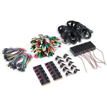
 Large Jumper Wire Kit - 700pcsSPARKFUN
¥12,980税込¥14,278
1個
欠品中
DescriptionYou asked for more wires, so you are going to get more wires! This is a large kit of jumper wires - cut, stripped, and pre-bent for your prototyping pleasure. Included with this kit are 14 various lengths of 22AWG wire - 2, 5, 7, 10, 12, 15, 17, 20, 22, 25, 50, 75, 100, and 125mm - 50 pieces of each.On top of getting five times more jumper wires that the smaller version, this large kit also comes with a durable carrying case with adjustable dividers in case you want to use it for something other than hooking up a project!
アズワン品番67-0425-54
 Arducam 5MP Plus OV5642 Mini Camera ModuleSPARKFUN
¥23,980税込¥26,378
1個
欠品中
DescriptionThe Arducam 5MP Plus OV5642 Mini provides an easy to use camera solution for those working with low-cost microcontrollers such as those used with Arduino and the RP2040 from Raspberry Pi. It's a general purpose 5MP camera module that's SPI enabled reducing the complexity of controlling the camera. It's a step up in performance from it's predecessor, the Arducam-M-5MP. The most impressive aspect being that it's possible to control more than one of these from the same microcontroller. It features a M12 mount or CS-Mount lens holder with the ability to change lenses. Best of all, there's code libraries for Arduino, STM32, Chipkit, Raspberry Pi, and BeagleBone Black.The Arducam 5MP Plus OV5642 Mini supports JPEG compression mode, single and multiple shoot mode, short movie recording, one-time capture multiple read operation, burst read operation, and low power mode.FeaturesPower supply 3.3V~5VActive array size:2592×1944SPI speed:Max 8MHzShutter:rolling shutterFrame buffer:8MBytePixel Size:1.4μm×1.4μmDefault M12 Lens:55°Resolution support:5MP, 1080p, 720p, VGA, QVGAFormat support:RAW, YUV, RGB, JPEGSize:34×24 mmWeight:20gTemperature Range:-10℃~+55℃Lens Specification:sensor size:1/4″; EFL:4.9mm; F/N:2.2; BFL:1.2mm; HFOV:60 degree(SKU:U6067)
アズワン品番67-0423-65
 SparkFun Air Velocity Sensor Breakout - FS3000-1005 QwiicSPARKFUN
¥17,980税込¥19,778
1個
33日以内出荷
DescriptionNeed to keep track of the airflow in your data center or around your servers? How about making sure your HVAC and air control systems are functioning at full capacity? Well, the new SparkFun FS3000-1005 Air Velocity Sensor Breakout can help you with all that and more! It's super easy and super quick(Qwiic!)to hook up.This breakout board is focused around Renesas' FS3000-1005, a surface-mount air velocity module with a range of 0-7.2m/s(0-16.2mph). It utilizes a MEMS thermopile-based sensor, features a digital output with 12-bit resolution and comprises a "solid" thermal isolation technology and silicon carbide coating to protect it from abrasive wear and water condensation.We've written an Arduino library to help you get started quickly. You can download the library through the Arduino library manager by searching 'SparkFun Air Velocity' or you can get the GitHub repo as a .zip file and install the library from there.The SparkFun Qwiic Connect System is an ecosystem of I2C sensors, actuators, shields and cables that make prototyping faster and less prone to error. All Qwiic-enabled boards use a common 1mm pitch, 4-pin JST connector. This reduces the amount of required PCB space, and polarized connections mean you can't hook it up wrong.Get Started with the Qwiic Air Velocity Sensor BreakoutFeaturesI2C address:0x28Air flow speed:0 - 7.23 m/sec(0 - 16.17mph)Accuracy:5 % of full scale flow range12-bit resolutionInput Voltage:2.7-3.3VAverage current draw:10mA
アズワン品番67-0427-58
 Alchitry Ft Element BoardSPARKFUN
¥10,980税込¥12,078
1個
33日以内出荷
DescriptionMeet the Alchitry Ft Element Board! Alchitry Elements are expansion boards similar to Arduino shields or Raspberry Pi HATs that work with your Au and Au+ FPGA Development Boards. The Ft Element is equipped with four 50-pin board to board connectors on the underside and top of the board that snap to the Alchitry Au and Au(+)boards. It also adds a USB 3.0 200MB/s high speed interface to your Alchitry board stack via the USB-C connector.Please note that this board is only functional with the higher end Au Au+ FPGA Dev boards that feature the Xilinx Artix 7.Get Started with our Learning FPGA TutorialsFeaturesUSB-C connector w/ 200MB/s data rate to board to board connectorsFor use with projects that require data transfer rates greater than standard on board USB to serial 12Mbaud
アズワン品番67-0423-43
 SparkFun 6 Degrees of Freedom Breakout - LSM6DSO QwiicSPARKFUN
¥5,198税込¥5,718
1個
欠品中
DescriptionThe SparkFun LSM6DSO 6 Degrees of Freedom Breakout is an accelerometer and gyroscope sensor with a giant 9kB FIFO buffer and embedded processing interrupt functions. Due to the capabilities and low cost of the LSM6DSO we've created this small breakout board just for you! Each LSM6DSO breakout has been designed to be super-flexible and can be configured specifically for many applications. With the LSM6DSO breakout you will be able to detect shocks, tilt, motion, taps, count steps, and even read the temperature!The LSM6DSO from STMicroelectronics is capable of reading accelerometer and gyroscope data up to 6.66kHz for more accurate movement sensing. As stated before this breakout also has the ability to buffer up to 9kB of data between reads, host other sensors, and drive interrupt pins all thanks to the LSM6DSO's built-in FIFO.Utilizing our handy Qwiic system, no soldering is required to connect it to the rest of your system. However, we still have broken out 0.1"-spaced pins in case you prefer to use a breadboard. Each pin has been broken out on the LSM6DSO, with one side of the board featuring power, I2C, and SPI functionality while the other side sporting pins that control auxiliary functionality and interrupt outputs. Please keep in mind that the LSM6DSO is a 3.3V device so supplying voltages greater than ~3.6V can permanently damage the IC. A logic level shifter is required for any development platform operating at 5V.The SparkFun Qwiic Connect System is an ecosystem of I2C sensors, actuators, shields and cables that make prototyping faster and less prone to error. All Qwiic-enabled boards use a common 1mm pitch, 4-pin JST connector. This reduces the amount of required PCB space, and polarized connections mean you can't hook it up wrong.Get Started With the SparkFun LSM6DSO Qwiic 6DoF GuideFeatures2x Qwiic connectorsI2C Address0x6B(default), 0x6AAccelerometer measurement range±2/±4/±8/±16 g full scaleGyro measurement range±125/±250/±500/±1000/±2000 dps full scaleEmbedded temperature sensor16-bit resolutionOperating voltage range1.71V to 3.6VTypically3.3Vif using the Qwiic cablePower consumption @ 1.8V0.55 mA in combo high-performance mode0.265 mA in combo low-power mode"Always on" experience with low power consumption for both accelerometer and gyroscopeI2C/SPI serial interface with main processor data synchronization featureSmart FIFO up to 9 kbyte based on features setOperating temperature range-40℃ to +85℃
アズワン品番67-0427-54
 SparkFun Cryptographic Co-Processor Breakout - ATECC608A QwiicSPARKFUN
¥1,498税込¥1,648
1個
33日以内出荷
DescriptionProduct Restrictions:To access certain features of the ATECC608A, users will need to contact Microchip and sign an NDA contract to obtain the complete datasheet. Due to the required NDA - technical support, an Arduino library, and hookup guide are not provided for users on this product.The SparkFun ATECC608A Cryptographic Co-processor Breakout allows you to add strong security to your IoT node, edge device, or embedded system. This includesasymmetricauthentication,symmetricAES-128 encryption/decryption, and much more. As stated above, the ATECC608A has limited Arduino support and the complete datasheet is under NDA with Microchip.This breakout board includes two Qwiic ports for plug and play functionality. Utilizing our handy Qwiic system, no soldering is required to connect it to the rest of your system. However, we still have broken out 0.1"-spaced pins in case you prefer to use a breadboard. The ATECC608A chip is capable of many cryptographic processes, including, but not limited to:Creating and securely storing unique asymmetric key pairs based on Elliptic Curve Cryptography(FIPS186-3).AES-128:Encrypt/Decrypt, Galois Field Multiply for GCMCreating and verifying 64-byte digital signatures(from 32-bytes of message data).Creating a shared secret key on a public channel via Elliptic Curve Diffie-Hellman Algorithm.SHA-256 HMAC Hash including off-chip context save/restoreInternal high quality FIPS random number generator.Embedded in the chip is a 10Kb EEPROM array that can be used for storing keys, certificates, data, consumption logging, and security configurations. Access to the sections of memory can then be restricted and the configuration locked to prevent changes. Each ATECC608A Breakout ships with a guaranteed unique 72-bit serial number and includes several security features to prevent physical attacks on the device itself, or logical attacks on the data transmitted between the device.A summary datasheet for the ATECC608A is available here. The full datasheet is under NDA with Microchip. You will need to contact them for access to the entire datasheet. Meanwhile, the ArduinoATECCX08 Library currently only supports the ATECC608A with SAMD21 Arduino boards.We do have much more support for the ATECC508A version of this chip. Please check out our ATECC508A Hookup Guide and Arduino Library(which includes six examples). This will get you familiar with the basics of elliptic curve cryptography and signing/verifying data with the ATECC508A version of the chip.Note:The I2C address of the ATECC608A is 0x60 and is software-configurable to any address. A multiplexer/Mux is required to communicate to multiple ATECC608A sensors at the default address when on a single bus. If you need to use more than one ATECC608A sensor at the default address, consider using the Qwiic Mux Breakout.Note:The ATECC608A can be only configured once before it isPERMANENTLYlocked. It is advisable that users purchase multiple boards in order to use other configurations and explore the advanced functions of the ATECC608A.Additionally, this boardIScapable of encrypting and decrypting data. However, to access these additional features, you will need to contact Microchip and sign an NDA contract to obtain the complete datasheet.It is recommended that an SparkFun RedBoard Turbo - SAMD21 Development Board is used with this product due to the buffer size required on the I2C bus.The SparkFun Qwiic Connect System is an ecosystem of I2C sensors, actuators, shields and cables that make prototyping faster and less prone to error. All Qwiic-enabled boards use a common 1mm pitch, 4-pin JST connector. This reduces the amount of required PCB space, and polarized connections mean you can't hook it up wrong.FeaturesOperating Voltage:2.0V-5.5V(Default on Qwiic System:3.3V)Active Current Draw(for ATECC608A):16 mASleep Current(for ATECC608A):<150 nAGuaranteed Unique 72-bit Serial Number10 Kb EEPROM Memory for Keys, Certificates, and DataStorage for up to 16 Keys256-bit Key LengthInternal High-Quality FIPS Random Number Generator(RNG)Configurable I2C Address(7-bit):0x60(Default)
アズワン品番67-0423-59
 SparkFun Configurable OpAmp Board - TSH82SPARKFUN
¥2,298税込¥2,528
1個
欠品中
DescriptionThe SparkFun TSH82 Configurable OpAmp Board was designed to give you the best combination of performance and flexibility that we could achieve by giving you two gain stages, each one independently accessible on the header pins. Each stage is natively configured as an inverting amplifier that can also be strung together to expand the capabilities of the TSH82 from STMicroelectronics. With the use of the jumpers on the back of the board, you can configure each stage for non-inverting operation, differential input, and DC input coupling.Electrically speaking, both stages on this board are identical. The default configuration is inverting with a gain of -4.7 with a bandwidth of almost 10MHz. Input signals are AC coupled, possess an input impedance of 10K with a low frequency cutoff of 15.9Hz. Outputs are also DC coupled, so don't forget to add a capacitor to the output if you're running a single-ended supply and need to strip out the DC component. The board will also operate with a single-ended DC power supply of 4.5V to 12V, or a bipolar supply from +/-2.25V to +/-6V.On the back of the board you'll find 10 solder jumpers that can be used to change the board's performance, but nothing there needs to be changed to use it in it's default state.Get Started With the Configurable OpAmp Board Guide
アズワン品番67-0420-03