カテゴリ
- 学童・教育用品(9)
絞り込み
ブランド
- SPARKFUN
- I ・O DATA(アイ・オー・データ)(511)
- SMC(1,000)
- MOXA(12)
- MICROCHIP(9)
- メディアカバーマーケット(5)
- ASUS(エイスース)(4)
- アズワン(3)
- unitech(3)
- シュナイダーエレクトリック(3)
- アイメックス(2)
- SICK(2)
- エレコム(1)
- omron(オムロン)(1)
- 島津製作所(1)
- リオン(1)
- ワゴジャパン(1)
- ユニテック(1)
- テクシオ・テクノロジー(GW INSTEK)(1)
- ブランドをもっと見る
「i-o data」の検索結果
特価
 I/O Expander - MCP23008SPARKFUN
¥639税込¥703
1個
33日以内出荷
DescriptionAdd another eight pins to your microcontroller using a MCP23008 port expander. The MCP23008 uses two I2C pins which can be shared with other I2C devices, and in exchange gives you eight general purpose pins. You can set each of eight pins to be input, output, or input with a pullup. There's even the ability to get an interrupt via an external pin when any of the inputs change so you don't have to keep polling the chip.Use this chip from 2.7-5.5V(good for any 3.3V or 5V setup), and you can sink/source up to 20mA from any of the I/O pins so this will work for LEDs and such. Team it up with a high-power MOSFET if you need more juice. DIP package means it will plug into any breadboard or perfboard.You can set the I2C address by tying the ADDR0-2 pins to power or ground, for up to eight unique addresses. That means eight chips can share a single I2C bus - that's 64 I/O pins!Features8-bit remote bidirectional I/O portHigh-speed I2C interface(MCP23008)Hardware address pinsConfigurable interrupt output pinConfigurable interrupt sourcePolarity Inversion register for input port data polarity config.External reset inputLow standby current:1 μA(max.)・ Operating voltage:1.8V to 5.5V @ -40℃ to +85℃ I2C @ 100 kHz SPI @ 5 MHz2.7V to 5.5V @ -40℃ to +85℃ I2C @ 400 kHz SPI @ 10 MHz4.5V to 5.5V @ -40℃ to +125℃ I2C @ 1.7 kHz SPI @ 10 MHz
アズワン品番67-0421-32
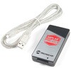
 MPLAB PICkit 4 In-Circuit DebuggerSPARKFUN
¥45,980税込¥50,578
1個
当日出荷
DescriptionThis is the PICkit 4, the official programmer from Microchip. The PICkit 4 allows debugging and programming of PIC(R), dsPIC(R), AVR, SAM and CEC flash microcontrollers and MPUs using the powerful graphical user interface of the MPLAB X Integrated Development Environment(IDE). The MPLAB PICkit 4 is connected to a PC using a high-speed 2.0 USB interface and can be connected to the target via an 8-pin Single In-Line(SIL)connector. The connector uses two device I/O pins and the reset line to implement in-circuit debugging and In-Circuit Serial Programming(TM)(ICSP(TM)). An additional micro SD card slot and the ability to be self-powered from the target means you can take your code with you and program on the go. Comes with a USB to micro-B USB cable.FeaturesPowered by a high-speed USB 2.0, no external power requiredReal-time executionMPLAB X IDE compatible(free copy included)Built-in over-voltage/short circuit monitorFirmware upgradeable from PC/web downloadFully enclosedTarget voltage of 1.20V to 5.5VCan supply up to 50mA of power to the targetMinimal current consumption at <100μA from targetDiagnostic LEDs(power, busy, error)Read/write program and data memory of microcontrollerErase of program memory space with verificationFreeze-peripherals at breakpoint8-pin single in-line header supports advanced interfaces such as 4-wire JTAG and Serial Wire Debug with streaming Data GatewayBackward compatible for demo boards, headers and target systems using 2-wire JTAG and ICSP
アズワン品番67-0425-08
 SparkFun Thing Plus - XBee3 Micro U.FLSPARKFUN
¥16,980税込¥18,678
1個
33日以内出荷
DescriptionThe XBee3 Thing Plus is an ultra capable and easy way for getting into wireless device development. The combination of XBee and Qwiic in a space conscious design represents a much needed update to our XBee offering. With 20 I/O pins and Lithium Polymer Ion battery management, the XBee3 Thing Plus has all the basics for quickly prototyping or developing a connected device such as a remote sensor. The Qwiic connector and JST connector for the battery make for a solder-less option when working with the board which shortens setup time.The new XBee3 Micro Module provides the classic all-but plug and play 802.15.4 2.4GHz wireless connection(Zigbee 3.0 Protocol)that makes it so desirable, but with a new addition of being programmable with MicroPython(32KB of memory available for it). RF data rates up to 250 Kbps and 200ft indoor ranges and up to 4000ft line-of-sight outdoor range. Communicating with/Configuring the module happens via an AT Command set or the Digi API, X-CTU, both locally or over-the-air. There's even a mobile version of X-CTU now; Digi XBee(R)Mobile.This variation features a U.FL antenna connector for longer range communications. Check out the related products for compatible antennas.Get Started With the SparkFun XBee3 Thing Plus GuideFeaturesXBee3 Micro ModuleSilicon Labs EFR32MG SoC250Kbps RF, 1Mbps Serial data ratesIndoor/Urban range up to 200 ft(60 m)Outdoor/RF Line of Sight range up to 4000 ft(1200 m)+8 dBm transmit power-103 dBm receiver sensitivityUART, I2C, SPI Interfaces(SPI currently not available at this time, but broken out on the board)ISM 2.4GHz Frequency Band(802.15.4)1MB of memory, 128KB RAM(32KB available for MicroPython)20 GPIO PinsConfigurable via X-CTU or AT Command set via both USB and Wirelessly(second XBee 3 device required for wireless configuration unless you're using the mobile app)Qwiic CompatibleOn-board charging circuit and connector for 3.3v Lithium Polymer Ion Batteries(see related products for compatible batteries)2.6VDC - 3.6VDC supply voltageU.FL Antenna Connector
アズワン品番67-0429-55
 SparkFun Thing Plus - XBee3 Micro Chip AntennaSPARKFUN
¥17,980税込¥19,778
1個
33日以内出荷
DescriptionThe XBee3 Thing Plus is an ultra-capable and easy way for getting into wireless device development. The combination of XBee and Qwiic in a space-conscious design represents a much-needed update to our XBee offering. With 20 I/O pins and Lithium-Polymer Ion battery management, the XBee3 Thing Plus has all the basics for quickly prototyping or developing a connected device such as a remote sensor. The Qwiic connector and JST connector for the battery make for a solder-less option when working with the board which shortens setup time.The new XBee3 Micro Module provides the classic, near plug and play 802.15.4 2.4GHz wireless connection(Zigbee 3.0 Protocol)that makes it so desirable, but with a new addition of being programmable with MicroPython(32KB of memory available for it). RF data rates up to 250Kbps and 200 ft indoor ranges and up to 4000 ft line-of-sight outdoor range. Communicating with/Configuring the module happens via an AT Command set or the Digi API, X-CTU, both locally or over-the-air. There's even a mobile version of X-CTU now; Digi XBee(R)Mobile.Note:This variation uses a chip antenna and is not compatible with external antennas.Get Started With the SparkFun XBee3 Thing Plus GuideFeaturesXBee3 Micro ModuleSilicon Labs EFR32MG SoC250Kbps RF, 1Mbps Serial data ratesIndoor/Urban range up to 200 ft(60 m)Outdoor/RF Line of Sight range up to 4000 ft(1200 m)+8 dBm transmit power-103 dBm receiver sensitivityUART, I2C, SPI Interfaces(SPI currently not available at this time, but broken out on the board)ISM 2.4GHz Frequency Band(802.15.4)1MB of memory, 128KB RAM(32KB available for MicroPython)20 GPIO PinsConfigurable via X-CTU or AT Command set via both USB and Wirelessly(second XBee 3 device required for wireless configuration unless you're using the mobile app)Qwiic CompatibleOn-board charging circuit and connector for 3.3v Lithium Polymer Ion Batteries(see related products for compatible batteries)2.6VDC - 3.6VDC supply voltageOn-board Chip Antenna
アズワン品番67-0429-57
 Himax CMOS Imaging Camera - HM01B0SPARKFUN
¥3,698税込¥4,068
1個
33日以内出荷
DescriptionThe HM01B0 from Himax Imaging is an ultra low power CMOS Monochrome Image Sensor that enables the integration of an "Always On" camera for computer vision applications such as gestures, intelligent ambient light and proximity sensing, tracking and object identification. The sensor allows the sensor to consume very low power of <2mW at QVGA 30FPS. This low power consumption and vision applications camera comes with a ribbon cable that mates to the camera connector populated on the following products:MicroMod Machine Learning Carrier BoardArtemis Development KitEdge Development Board - Apollo3 BlueThe HM01B0 contains 320×320 pixel resolution and supports a 320×240 window mode which can be readout at a maximum frame rate of 60FPS, and a 2×2 monochrome binning mode with a maximum frame rate of 120FPS. The video data is transferred over a configurable 1bit, 4bit or 8bit interface with support for frame and line synchronization. The sensor integrates black level calibration circuit, automatic exposure and gain control loop, self-oscillator and motion detection circuit with interrupt output to reduce host computation and commands to the sensor to optimize the system power consumption.FeaturesImage SensorUltra Low Power Image Sensor(ULPIS)designed for Always On vision devices and applicationsHigh sensitivity 3.6μ BrightSenseTM pixel technology320×320 active pixel resolution with support for QVGA window, vertical flip and horizontal mirror readoutProgrammable black level calibration target, frame size, frame rate, exposure, analog gain(up to 8x)and digital gain(up to 4x)Automatic exposure and gain control loop with support for 50 / 60Hz flicker avoidanceFlexible 1bit, 4bit and 8bit video data interface with video frame and line syncMotion Detection circuit with programmable ROI and detection threshold with digital output to serve as an interruptOn-chip self oscillatorI2C 2-wire serial interface for register accessHigh CRA for low profile module designSensor ParametersActive Pixel Array 320×320Pixel Size 3.6 μm×3.6 μmFull Image Area 1152 μm×1152 μmDiagonal(Optical Format)1.63 mm(1/11″)Scan Mode:ProgressiveShutter Type:Electronic Rolling ShutterFrame Rate MAX 51 fps @ 320×320, 60 fps @ 320×240(QVGA)CRA(maximum)30℃Sensor SpecificationsSupply Voltage:Analog - 2.8 V, Digital - 1.5V(Internal LDO:1.5V - 2.8V), I/O - 1.5 - 2.8VInput Reference Clock:3 - 50 MHzSerial Interface(I2C):2-wire, 400 KHz max.Video Data Interface:1b, 4b, 8b with frame / line SYNCOutput Clock Rate MAX:50 MHz for 1bit, 12.5 MHz for 4bit, 6.25 MHz for 8bitEst. Power Consumption(include IO with 5pF load):QVGA 60FPS(Typical)<4 mWQVGA 30FPS(Typical)<2 mW
アズワン品番67-0427-08
 ArduinoMega 2560 R3SPARKFUN
¥18,980税込¥20,878
1個
33日以内出荷
DescriptionArduino is an open-source physical computing platform based on a simple i/o board and a development environment that implements the Processing/Wiring language. Arduino can be used to develop stand-alone interactive objects or can be connected to software on your computer(e.g. Flash, Processing, MaxMSP). The open-source IDE can be downloaded for free(currently for Mac OS X, Windows, and Linux).The Arduino Mega is a microcontroller board based on the ATmega2560. It has 54 digital input/output pins(of which 14 can be used as PWM outputs), 16 analog inputs, 4 UARTs(hardware serial ports), a 16 MHz crystal oscillator, a USB connection, a power jack, an ICSP header, and a reset button. It contains everything needed to support the microcontroller; simply connect it to a computer with a USB cable or power it with a AC-to-DC adapter or battery to get started.Never fear for accidental electrical discharge, either since since the Mega also includes a plastic base plate to protect it!The Mega 2560 R3 also adds SDA and SCL pins next to the AREF.In addition, there are two new pins placed near the RESET pin. One is the IOREF that allow the shields to adapt to the voltage provided from the board.The other is a not connected and is reserved for future purposes.The Mega 2560 R3 works with all existing shields but can adapt to new shields which use these additional pins.Not sure which Arduino or Arduino-compatible board is right for you? Check out our Arduino Buying Guide!FeaturesATmega2560 microcontrollerInput voltage - 7-12V54 Digital I/O Pins(14 PWM outputs)16 Analog Inputs256k Flash Memory16Mhz Clock Speed
アズワン品番67-0349-13
 SparkFun GPS Breakout - NEO-M9N, SMA QwiicSPARKFUN
¥22,980税込¥25,278
1個
33日以内出荷
DescriptionThe SparkFun NEO-M9N GPS Breakout is a high quality GPS board with equally impressive configuration options including SMA. The NEO-M9N module is a 92-channel u-blox M9 engine GNSS receiver, meaning it can receive signals from the GPS, GLONASS, Galileo, and BeiDou constellations with ~1.5 meter accuracy. This breakout supports concurrent reception of four GNSS. This maximizes position accuracy in challenging conditions increasing, precision and decreases lock time; and thanks to the onboard rechargeable battery, you'll have backup power enabling the GPS to get a hot lock within seconds! Additionally, this u-blox receiver supports I2C(u-blox calls this Display Data Channel)which makes it perfect for the Qwiic compatibility so we don't have to use up our precious UART ports. Utilizing our handy Qwiic system, no soldering is required to connect it to the rest of your system. However, we still have broken out 0.1"-spaced pins in case you prefer to use a breadboard.The NEO-M9N module detects jamming and spoofing events and can report them to the host, so that the system can react to such events. A SAW(Surface Acoustic Wave)filter combined with an LNA(Low Noise Amplifier)in the RF path is integrated into the NEO-M9N module which allows normal operation even under strong RF interferences.U-blox based GPS products are configurable using the popular, but dense, windows program called u-center. Plenty of different functions can be configured on the NEO-M9N:baud rates, update rates, geofencing, spoofing detection, external interrupts, SBAS/D-GPS, etc. All of this can be done within the SparkFun Arduino Library!The SparkFun NEO-M9N GPS Breakout is also equipped with an on-board rechargeable battery that provides power to the RTC on the NEO-M9N. This reduces the time-to-first fix from a cold start(~24s)to a hot start(~2s). The battery will maintain RTC and GNSS orbit data without being connected to power for plenty of time.This product requires an antenna:Be sure to check out the related products/hookup accessories and pick a suitable SMA antenna for your project.The SparkFun Qwiic Connect System is an ecosystem of I2C sensors, actuators, shields and cables that make prototyping faster and less prone to error. All Qwiic-enabled boards use a common 1mm pitch, 4-pin JST connector. This reduces the amount of required PCB space, and polarized connections mean you can't hook it up wrong.The NEO-M9N GPS Breakout can also be automatically detected, scanned, configured, and logged using the OpenLog Artemis datalogger system. No programming, soldering, or setup required!Get Started With the SparkFun NEO-M9N GPS GuideFeaturesIntegrated SMA connector for use with antenna of your choice92-Channel GNSS Receiver1.5m Horizontal Accuracy25Hz Max Update Rate(four concurrent GNSS)Time-To-First-Fix:Cold:24sHot:2sMax Altitude:80,000mMax G:≦4Max Velocity:500m/sVelocity Accuracy:0.05m/sHeading Accuracy:0.3 degreesTime Pulse Accuracy:30ns3.3V VCC and I/OCurrent Consumption:~31mA Tracking GPS+GLONASSSoftware ConfigurableGeofencingOdometerSpoofing DetectionExternal InterruptPin ControlLow Power ModeMany others!Supports NMEA, UBX, and RTCM protocols over UART or I2C interfaces
アズワン品番67-0423-87
 SparkFun GPS Breakout - ZOE-M8Q QwiicSPARKFUN
¥14,980税込¥16,478
1個
33日以内出荷
DescriptionThe SparkFun ZOE-M8Q GPS Breakout is a high accuracy, miniaturized, GPS board that is perfect for applications that don't possess a lot of space. The on-board ZOE-M8Q is a 72-channel GNSS receiver, meaning it can receive signals from the GPS, GLONASS, BeiDou, and Galileo constellations. This increases precision and decreases lock time and thanks to the onboard rechargable battery you'll have backup power enabling the GPS to get a hot lock within seconds! Additionally, this u-blox receiver supports I2C(u-blox calls this Display Data Channel)which made it perfect for the Qwiic compatibility so we don't have to use up our precious UART ports. Utilizing our handy Qwiic system, no soldering is required to connect it to the rest of your system. However, we still have broken out 0.1"-spaced pins in case you prefer to use a breadboard.U-blox based GPS products are configurable using the popular, but dense, windows program called u-center. Plenty of different functions can be configured on the ZOE-M8Q:baud rates, update rates, geofencing, spoofing detection, external interrupts, SBAS/D-GPS, etc. All of this can be done within the SparkFun Arduino Library. We've also made sure to configure the UART pin grouping on the breakout to an industry standard to insure that it easily connects to a Serial Basic.The SparkFun ZOE-M8Q GPS Breakout is also equipped with an on-board rechargeable battery that provides power to the RTC on the ZOE-M8Q. This reduces the time-to-first fix from a cold start(~30s)to a hot start(~1s). The battery will maintain RTC and GNSS orbit data without being connected to power for up to five hours. Since the ZOE-M8Q is a tiny GPS receiver and to minimize its footprint, we've added a U.FL connector to allow the use of both large standard ceramic antennas as well as very small chip scale antennas.Note:The I2C address of the ZOE-M8Q is 0x42 and is software configurable. A multiplexer/Mux is required to communicate to multiple ZOE-M8Q sensors on a single bus. If you need to use more than one ZOE-M8Q sensor consider using the Qwiic Mux Breakout.The SparkFun Qwiic Connect System is an ecosystem of I2C sensors, actuators, shields and cables that make prototyping faster and less prone to error. All Qwiic-enabled boards use a common 1mm pitch, 4-pin JST connector. This reduces the amount of required PCB space, and polarized connections mean you can't hook it up wrong.The ZOE-M8Q GPS Breakout can also be automatically detected, scanned, configured, and logged using the OpenLog Artemis datalogger system. No programming, soldering, or setup required!Get Started With the SparkFun ZOE-M8Q Hookup GuideFeatures72-Channel GNSS Receiver2.5m Horizontal Accuracy18Hz Max Update RateTime-To-First-Fix:Cold:26sHot:1sMax Altitude:50,000mMax G:≦4Max Velocity:500m/sVelocity Accuracy:0.05m/sHeading Accuracy:0.3 degreesTime Pulse Accuracy:30ns3.3V VCC and I/OCurrent Consumption:~29mA Tracking GPS+GLONASSSoftware ConfigurableGeofencingOdometerSpoofing DetectionExternal InterruptPin ControlLow Power ModeMany others!Supports NMEA, UBX, and RTCM protocols over UART or I2C interfaces
アズワン品番67-0423-76
 Cherry MX Switch BreakoutSPARKFUN
¥799税込¥879
1個
33日以内出荷
DescriptionCherry MX Keyswitches are top-of-the-line mechanical keyboard switches. They're satisfyingly "clicky", reliable up to tens-of-millions of key presses, and a standard in gaming and programming keyboards across the globe. With the SparkFun Cherry MX Switch Breakout we have made the switches more easily adaptable to breadboard or perfboard-based projects. The Cherry MX Switch Breakout is a perfect prototyping tool for projects ranging from a single-key user-input to fully-custom 101-key keyboards.In addition to breaking out the switch contacts to breadboard-compatible headers, the Cherry MX Switch Breakout also provides access to an optional switch-mounted LED. Plus, the pin break-outs are designed with keyboard matrix-ing in mind, so you can interconnect as many boards as you'd like into a row-column configuration, keeping the I/O-pin requirements as low as possible.Note:If you are looking for a Cherry MX Switch to use with this breakout, we've got you covered! CLICK HERE!Get Started with the Cherry MX Switch GuideFeaturesSupport for 3mm LEDFootprint for LED current-limiting resistorFootprint for switch-isolating diodeChain-able in row/column matricesDesigned to match standard key spacing and keyboard row offsets
アズワン品番67-0419-91