カテゴリ
- 学童・教育用品(28)
絞り込み
ブランド
- SPARKFUN
- SCHURTER(10)
- SIEMENS(6)
- SKF(日本エスケイエフ)(4)
- FINDER(3)
- RS PRO(2)
- Signalway Antibody(2)
- ワゴジャパン(1)
- INNO(1)
- フエニックス・コンタクト(1)
- TE Connectivity Japan(旧:TYCOELECTRONICS(タイコエレクトロニクス))(1)
- DIGILENT(1)
- TELEMECANIQUE SENSORS(1)
- VISATON(1)
- MARWI(1)
「inar inno」の検索結果
 SparkFun Qwiic Shield for Arduino NanoSPARKFUN
¥1,698税込¥1,868
1個
33日以内出荷
DescriptionThe SparkFun Qwiic Shield for Arduino Nano provides you with a quick and easy way to enter into SparkFun's Qwiic ecosystem with your Arduino Nano board. The Qwiic shield connects the I2C bus(GND, 3.3V, SDA and SCL)on your Arduino Nano to
アズワン品番67-0423-12
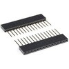
 Arduino Nano Stackable Header KitSPARKFUN
¥849税込¥934
1個
欠品中
DescriptionThese stackable headers are made to work with the SparkFun Qwiic Shield for Arduino Nano or any comparable shield to connect the shield with a Arduino Nano footprint. This set includes two 15-pin headers; the pins are spaced by 0.1".Each set of headers allows you to stack a Qwiic Nano shield on top of your Arduino Nano or plug them into a solderless breadboard.Note:Soldering is required for functionality and physical attachment to a shield or board.
アズワン品番67-0425-81
 SparkFun RTK SurveyorSPARKFUN
¥129,800税込¥142,780
1個
33日以内出荷
DescriptionThe SparkFun RTK Surveyor is an easy to use GNSS receiver for centimeter-level positioning. Perfect for surveying, this preprogrammed device can also be used for autonomous driving, navigation, asset tracking and any other application where there is a clear view of the sky. The RTK Surveyor can also be used as a base station. With the flick of a switch, two RTK Surveyors can be used to create an RTK system capable of 14mm horizontal positional accuracy. The built-in Bluetooth(R)connection via an ESP32 WROOM enables the user to use the RTK Surveyor with their choice of GIS application on a phone or tablet. The built in battery allows field use for up to four hours and is compatible with common USB battery banks.This device can be used in four modes:GNSS Positioning(~30cm accuracy)GNSS Positioning with RTK(1.4cm accuracy)GNSS Base StationGNSS Base Station NTRIP ServerIn Position mode the device receives L1/L2 signals from a user-provided antenna and the high-grade GNSS receiver provides lat/long and altitude with accuracies around 300mm.In Positioning with RTK mode the device receives L1/L2 signals from the antenna and correction data from a base station. The correction data can be obtained from a cellular link to online correction sources or over a radio link to a 2nd RTK Surveyor setup as a base station.In Base Station mode the device is mounted to a temporary position(like a tripod)and begins transmitting correction data over a radio or internet connection. A base is often used in conjunction with a second unit set to 'Positioning with RTK' to obtain the 14mm relative accuracy.In Base Station NTRIP Server mode the device is mounted to a semi or permanently fixed position(like a roof)and connects over WiFi to transmit the correction data to a NTRIP caster so that any rover can access the correction data over a cellular or internet connection. This type of base is a very easy way to setup a very precise absolute correction source.Two cables are provided with the RTK Surveyor allowing a user to plug on our easy to use Serial Telemetry Radios or their own radio link. If a local correction source is within 10km, a user can also use their phone to provide correction data over the Bluetooth(R)link(no external radio needed!).Note:The SparkFun RTK Surveyor is just the enclosed device and does NOT include an antenna, serial telemetry radio, or associated mounting pieces. These items will need to be purchased separately from the Hookup Accessories below.Get Started With the SparkFun RTK Surveyor GuideFeaturesGNSS Receiver:ZED-F9PConcurrent reception of GPS, GLONASS, Galileo and BeiDouReceives both L1C/A and L2C bandsCurrent:68mA - 130mA(varies with constellations and tracking state)Time to First Fix:25s(cold), 2s(hot)Max Navigation Rate:PVT(basic location over UBX binary protocol)- 25HzRTK - 20HzRaw - 25HzHorizontal Position Accuracy:2.5m without RTK0.010m with RTKMax Altitude:50km(31 miles)Max Velocity:500m/s(1118mph)Bluetooth(R)Transceiver:ESP32 WROOMXtensa(R)dual-core 32-bit LX6 microprocessorUp to 240MHz clock frequency16MB of flash storage520kB internal SRAMIntegrated 802.11 BGN WiFi transceiverIntegrated dual-mode Bluetooth(R)(classic and BLE)Hardware accelerated encryption(AES, SHA2, ECC, RSA-4096)2.5 μA deep sleep currentOverall DeviceInternal Battery:LiPo 1000mAh with 500mA chargingRadio Port:3.3V TTL Serial(57600bps RTCM TX/RX)Data Port:3.3V TTL Serial(115200bps NMEA)Weight:132g(entire device including battery)Dimensions:118mm×79mm×30mm(4.7in×3.1in×1.2in)1x Qwiic Connector1x microSD Socket for optional loggingChanges:This version(which replaces SPX-17369)uses a reinforced edge mount SMA connector for better resiliency when a fixed 'stub' antenna is used.
アズワン品番67-0423-95
 LilyPad LilyMini ProtoSnapSPARKFUN
¥5,998税込¥6,598
1個
33日以内出荷
DescriptionThe LilyMini ProtoSnap is a great way to get started learning about creating interactive e-textile circuits before you start sewing. Like other LilyPad ProtoSnap boards, the LilyMini ProtoSnap has all of its pieces wired together out of the box, enabling you to test the circuit's function before you sew. At the center of the board is a pre-programmed LilyMini microcontroller connected to a LilyPad Light Sensor, LilyPad Button and two pairs of LilyPad LEDs.The LilyMini ProtoSnap ships with pre-loaded code that uses all the LilyPad pieces connected to it. This sample code has three modes, which can be selected by pressing the LilyPad Button on the bottom-left side of the ProtoSnap. The built-in RGB LED on the LilyMini will change color to indicate which mode has been selected:White:All LEDs on.Magenta:LEDs fade in and out in a breathing pattern. When the light sensor is covered, LEDs fade faster.Cyan:LEDs off. When the light sensor is covered, LEDs will twinkle.The LilyMini board, at the center of the ProtoSnap, has a built-in battery holder for a CR2032 battery(included). On the opposite side of the LilyMini you will find the SAMD11 brain, which controls the ProtoSnap.Note:A portion of this sale is given back to Dr. Leah Buechley for continued development and education in e-textiles.Note:The LilyPad LilyMini ProtoSnap does NOT include sewing needles or conductive thread. These items will need to purchased separately.Warning:You cannot reprogram this product and any attempt at programming is at your own risk!Get Started with the LilyMini ProtoSnap Guide
アズワン品番67-0422-40
 LilyPad E-Sewing ProtoSnap KitSPARKFUN
¥4,298税込¥4,728
1個
33日以内出荷
DescriptionThe LilyPad E-Sewing ProtoSnap Kit is a great way to incorporate buttons and switches into an e-textile project without any programming required. Like other LilyPad ProtoSnap series boards, the individual pieces of the included E-Sewing ProtoSnap are pre-wired --- allowing you to try out the function of the circuit before sewing. We have also included a CR2032 battery, needle set, conductive thread bobbin and a swatch of white felt. With all of these parts combined and the featured guide(found in the Documents tab), you will be able to plan and create fantastic projects straight out of the box!The E-Sewing ProtoSnap includes three white LilyPad LEDs:two connected to a LilyPad Slide Switch and one connected to a LilyPad Button Board. A LilyPad Coin Cell Battery Holder with the included CR2032 coin cell battery provides all the power you need for the circuit. All you need to do is design how you want your project to be laid out, and then snap everything apart!Note:A portion of this sale is given back to Dr. Leah Buechley for continued development and education in e-textiles.Note:Due to the requirements of shipping the battery in this kit, orders may take longer to process and therefore do not qualify for same-day shipping. Additionally, these batteries cannot be shipped via Ground or Economy methods to Alaska or Hawaii. Sorry for any inconvenience this may cause.Get Started with the LilyPad E-Sewing ProtoSnap Guide
アズワン品番67-0424-14
 USB to TTL Serial Cable 5V VCCSPARKFUN
¥5,198税込¥5,718
1個
欠品中
DescriptionThis is a USB to TTL Serial Cable which allows for a simple way to connect TTL interface devices to USB. The I/O pins of this cable are configured to operate at 3.3V specifically with a Raspberry Pi with each serial pin broken apart. Thanks to its separated pins, this cable is a perfect candidate for powering, connecting, and accessing the login and debug console on an older-version Raspberry Pi.The FTDI cable is designed around an FT232, which is housed in a USB-A connector. The other side of the cable is terminated with a separated 4-pin connector with the following pinout:RX(Yellow), TX(Orange), VCC(5V)(Red), and GND(Black). A link to the FTDI drivers can be found in theDocumentssection above.Note:Please be aware that while the I/O pins in this cableoperate at 3.3V, the VCC pin is 5V. The VCC pin is NOT 3.3V like theI/O pins.
アズワン品番67-0420-67
 Cable Carrier - 10x15mm 0.5m LengthSPARKFUN
¥4,598税込¥5,058
1個
欠品中
DescriptionNo, this isn't a tank tread, this is a 0.5m long Cable Carrier with 10x15mm bits composing its main body and two screw fasteners at each end for efficient mounting. Sometimes called a "drag chain," each carrier can be used in projects with a large number of moving parts to protect internally installed cables, pipes, or tubes so they can be bent and moved while remaining protected. Cable carriers can most commonly been found in 3D printers and CNC machines but they can be used in any situation where you need cables or tubes to bend without risk of them being damaged or wearing out prematurely.This specific cable carrier offers inner dimensions of 10mm(height)by 15mm(wide), an outer width of 22mm, and a bend radius of 20mm. Additionally, these carriers are thin enough to fit into an Actobotics channel, making custom slide machines or other projects even easier to manage. Much like a chain, individual links can be added or removed to make custom lengths.FeaturesInner Bit Height:10mmInner Bit Width:15mmOuter Bit Height:14Outer Bit Width:22mmMinimum Bend Radius:20mmReinforced Nylon Structure
アズワン品番67-0426-29
 SparkFun I2S Audio Breakout - MAX98357ASPARKFUN
¥1,998税込¥2,198
1個
33日以内出荷
DescriptionThe SparkFun I2S Audio Breakout board uses the MAX98357A digital to analog converter(DAC), which converts I2S(not be confused with I2C)audio to an analog signal to drive speakers. The I2S Audio Breakout converts the digital audio signals using the I2S standard to an analog signal and amplifies the signal using a class D amplifier which can deliver up to 3.2W of power into a 4Ω load. The board can be configured to output only the left channel audio, right channel, or both.The SparkFun I2S Audio Breakout board is fairly simple, requiring only a few pin connections to get it up and working. By default the board is configured in "mono" operation, meaning the left and right signals are combined together to drive a single speaker. If you want a separate speaker for the left and right audio channels you'll need to cut the mono jumper. In addition to being able to select the audio channel output, the gain can also be configured in a few ways. The gain of the amplifier can be configured from as low as +3dB to as high as +15dB. While the channel selection can be configured on board, the gain however is controlled externally using the gain pin. By default, the board is configured for +9dB, but can be easily changed!Get Started with the SparkFun I2S Audio Breakout GuideFeaturesSupply Voltage Range:2.5V - 5.5V.Output Power:3.2W into 4Ω at 5V.Output Channel Selection:Left, Right, or Left/2 + Right/2(Default).Sample Rate:8kHz - 96kHz.Sample Resolution:16/32 bit.Quiescent Current:2.4mA.Filterless Class D OutputsNo MCLK RequiredClick and Pop ReductionShort-Circuit and Thermal Protection.
アズワン品番67-0422-64
 Rotary Potentiometer - 100k Ohm, Linear Panel MountSPARKFUN
¥1,098税込¥1,208
1個
欠品中
DescriptionAn adjustable potentiometer can open up many interesting user interfaces. With this rotary potentiometer just turn the dial and the resistance changes. This potentiometer from Bourns has a 1/4" metal knurled shaft diameter, solder lug terminals, no detents, and has a 100K linear taper.Connect VCC to an outer pin, GND to the other, and the center pin will have a voltage that varies from 0 to VCC depending on the rotation of the pot. Hook the center pin to an ADC on a microcontroller and get a variable input from the user!
アズワン品番67-0421-09
 TRRS Audio Plug - 3.5mm MetalSPARKFUN
¥579税込¥637
1個
欠品中
DescriptionTRRS connectors are the audio-style connectors that you see on some phones, MP3 players and development boards. TRRS stands for "Tip, Ring, Ring, Sleeve," which reflects the fact that, unlike a standard stereo connector, this actually has three conductors and a ground. Some devices use the extra conductor for a microphone(like hands-free headsets)or to carry a video signal(like in some MP3/MP4 players). If you're hacking on something that has a 4-conductor audio jack, being able to plug straight in will keep your build clean and simple.Note:This plug allows you to add a custom length of wire to your connector or repair a broken shroud on an existing cable you just cannot live without. Unfortunately, the supplier has not provided a datasheet or dimensional drawing please see the similar documents provided by other SparkFun products on the "documents" tab.
アズワン品番67-0421-42
 LilyPad E-Sewing ProtoSnapSPARKFUN
¥2,198税込¥2,418
1個
33日以内出荷
DescriptionThe LilyPad E-Sewing ProtoSnap is a great way to explore how buttons and switches behave in simple e-sewing circuits before crafting your project. Like other LilyPad ProtoSnap series boards, the individual pieces of the board are pre-wired --- allowing you to try out the function of the circuit before sewing. There is no programming required to use this ProtoSnap, and it can be used right away!The E-Sewing ProtoSnap includes three white LilyPad LEDs:two connected to a LilyPad Slide Switch and one connected to a LilyPad Button Board. A LilyPad Coin Cell Battery Holder with a CR2032 coin cell battery provides all the power you need for the circuit. All you need to do is design how you want your project to be laid out, and then snap everything apart!Note:A portion of this sale is given back to Dr. Leah Buechley for continued development and education in e-textiles.Note:Due to the requirements of shipping the included battery, orders may take longer to process and therefore do not qualify for same-day shipping. Additionally, these batteries cannot be shipped via Ground or Economy methods to Alaska or Hawaii. Sorry for any inconvenience this may cause.Get Started with the LilyPad E-Sewing ProtoSnap Guide
アズワン品番67-0422-55
 SparkFun Soil Moisture Sensor with Screw TerminalsSPARKFUN
¥2,198税込¥2,418
1個
33日以内出荷
DescriptionThe SparkFun Soil Moisture Sensor is a simple breakout for measuring the moisture in soil and similar materials. The soil moisture sensor is pretty straightforward to use. The two large, exposed pads function as probes for the sensor, together acting as a variable resistor. The more water that is in the soil means the better the conductivity between the pads will be, resulting in a lower resistance and a higher SIG out. This version of the Soil Moisture Sensor includes a 3-pin screw pin terminal pre-soldered to the board for easy wiring and setup.To get the SparkFun Soil Moisture Sensor functioning, all you will need is to connect the VCC and GND pins to your Arduino-based device(or compatible development board). You will receive a SIG out, which will depend on the amount of water in the soil. One commonly known issue with soil moisture senors is their short lifespan when exposed to a moist environment. To combat this, we've had the PCB coated in gold finishing(ENIG, or Electroless Nickel Immersion Gold).Note:Check the Hookup Guide below for assembly and weatherproofing instructions, as well as a simple example project that you can put together yourself!Get Started with the Soil Moisture Sensor Guide
アズワン品番67-0426-56
 SparkFun FM Tuner Evaluation Board - Si4703SPARKFUN
¥7,298税込¥8,028
1個
33日以内出荷
DescriptionThis is an evaluation board for the Silicon Laboratories Si4703 FM tuner chip. Beyond enabling you to tune in to FM radio stations, the Si4703 is also capable of detecting and processing both Radio Data Service(RDS)and Radio Broadcast Data Service(RBDS)information. The Si4703 even does a very good job of filtering and carrier detection. It also enables data such as the station ID and song name to be displayed to the user.Using this board, you will be able to pick up multiple stations just as well as with a standard FM radio. The board breaks out all major pins and makes it easy to incorporate this great chip into your next radio project. The power bus, the 3.3V and GND pins are broken out For communication. The breakout provides access to SDIO and SCLK for I2C communication while RST can be used for easy resetting. The SEN pin enables the user to change the mode of functionality of the IC. The last two pins broken out are GPIO1 and GPIO2 which can be used as general input/output pins, but also can be used for things like the RDS ready, seeking or tuning functions.Keep in mind, by plugging headphones into the 3.5mm audio jack, you effectively use the cable in your headphones as an antenna! Therefore, this board does not require an external antenna if using headphones or a 3.5mm audio cable longer than 3 feet.
アズワン品番67-0429-34
 SparkFun Thing Plus - RP2040SPARKFUN
¥6,698税込¥7,368
1個
33日以内出荷
DescriptionThe SparkFun Thing Plus - RP2040 is a low-cost, high performance board with flexible digital interfaces featuring the Raspberry Pi Foundation's RP2040 microcontroller. Besides the Thing Plus orFeatherfootprint(with 18 GPIO pins), the board also includes an SD card slot, 16MB(128Mbit)flash memory, a JST single cell battery connector(with a charging circuit and fuel gauge sensor), an addressable WS2812 RGB LED, JTAG PTH pins, four(4-40 screw)mounting holes, and our signature Qwiic connector.The RP2040 contains two ARM Cortex-M0+ processors(up to 133MHz)and features:264kB of embedded SRAM in six banks6 dedicated IO for SPI Flash(supporting XIP)30 multifunction GPIO:Dedicated hardware for commonly used peripheralsProgrammable IO for extended peripheral supportFour 12-bit ADC channels with internal temperature sensor(up to 0.5 MSa/s)USB 1.1 Host/Device functionalityThe RP2040 is supported with both C/C++ and MicroPython cross-platform development environments, including easy access to runtime debugging. It has UF2 boot and floating-point routines baked into the chip. While the chip has a large amount of internal RAM, the board includes an additional 16MB of external QSPI flash memory to store program code.The SparkFun Qwiic Connect System is an ecosystem of I2C sensors, actuators, shields and cables that make prototyping faster and less prone to error. All Qwiic-enabled boards use a common 1mm pitch, 4-pin JST connector. This reduces the amount of required PCB space, and polarized connections mean you can't hook it up wrong.Get Started With the Thing Plus RP2040 Hookup GuideFeaturesSparkFun Thing Plus - RP2040 FeaturesRaspberry Pi Foundation's RP2040 microcontroller16MB QSPI Flash MemoryJTAG PTH PinsThing Plus(or Feather)Form-Factor:18[1]x Multifunctional GPIO Pins[2]Four available 12-bit ADC channels with internal temperature sensor(500kSa/s)Up to eight 2-channel PWMUp to two UARTsUp to two I2C busesUp to two SPI busesUSB-C Connector:USB 1.1 Host/Device functionality2-pin JST Connector for a LiPo Battery(not included)500mA charging circuitQwiic ConnectorButtons:BootResetLEDs:PWR- Red 3.3V power indicatorCHG- Yellow battery charging indicator25- Blue status/test LED(GPIO 25)WS2812- Addressable RGB LED(GPIO 08)Four Mounting Holes:4-40 screw compatibleDimensions:2.3"×0.9"RP2040 General FeaturesDual Cortex M0+ processors, up to 133 MHz264 kB of embedded SRAM in 6 banks6 dedicated IO for QSPI flash, supporting execute in place(XIP)30 programmable IO for extended peripheral supportSWD interfaceTimer with 4 alarmsReal time counter(RTC)USB 1.1 Host/Device functionalitySupported programming languagesMicroPythonC/C++1.Note:GPIO 08is not included in this count, as it passes through the WS2812 addressable RGB LED first.GPIO 07andGPIO 23are counted as a single GPIO because they are tied together.2.Note:The GPIO pins are programmable so you can reconfigure the pins! Check out the RP2040 datasheet for more information on the GPIO functionality.
アズワン品番67-0423-56
 SparkFun Capacitive Touch Slider - CAP1203 QwiicSPARKFUN
¥2,498税込¥2,748
1個
33日以内出荷
DescriptionDo you want to replace a slider or a button on your art project or science experiment with a more interesting interface? This Capacitive Touch Slider is a "Qwiic" and easy way to add capacitive touch to your next project. With the board's built in touch pads, you can immediately start playing with the touch capabilities as three unique touch inputs or as a slider. You can also enable a touch input to act as a power button, customize the sensitivity for your own touch pads, and play with the interrupt alert LED. Utilizing our Qwiic system, no soldering is required to connect it to the rest of your system. However, we have broken out 0.1"-spaced pins in case you prefer to use a breadboard or create your own touch pads.On the front of the board, there is an arrow shape which contains three separate capacitive touch pads. We also broke out the capacitive touch sensor lines as plated through-holes on the top of the board. You can use these pins to connect to your own capacitive touch pads. The CS1 pin connects to the left pad, the CS2 pin connects to the middle pad, and the CS3 pin connects to the right pad.NOTE:The I2C address of the CAP1203 is 0x28 and is hardware defined. A multiplexer/Mux is required to communicate to multiple CAP1203 sensors on a single bus. If you need to use more than one CAP1203 sensor consider using the Qwiic Mux Breakout.The SparkFun Qwiic connect system is an ecosystem of I2C sensors, actuators, shields and cables that make prototyping faster and less prone to error. All Qwiic-enabled boards use a common 1mm pitch, 4-pin JST connector. This reduces the amount of required PCB space, and polarized connections mean you can't hook it up wrong.Get Started with the SparkFun Capacitive Touch Slider GuideFeaturesCapacitive Touch3 unique capacitive touch inputsFeaturesEmulated sliderPower button settingProgrammable sensitivityAutomatic recalibrationI2C Address:0x28Qwiic EnabledOperating RangeSupply Voltage:3.3V - 5V
アズワン品番67-0427-06
 SparkFun GPS Breakout - ZOE-M8Q QwiicSPARKFUN
¥14,980税込¥16,478
1個
33日以内出荷
DescriptionThe SparkFun ZOE-M8Q GPS Breakout is a high accuracy, miniaturized, GPS board that is perfect for applications that don't possess a lot of space. The on-board ZOE-M8Q is a 72-channel GNSS receiver, meaning it can receive signals from the GPS, GLONASS, BeiDou, and Galileo constellations. This increases precision and decreases lock time and thanks to the onboard rechargable battery you'll have backup power enabling the GPS to get a hot lock within seconds! Additionally, this u-blox receiver supports I2C(u-blox calls this Display Data Channel)which made it perfect for the Qwiic compatibility so we don't have to use up our precious UART ports. Utilizing our handy Qwiic system, no soldering is required to connect it to the rest of your system. However, we still have broken out 0.1"-spaced pins in case you prefer to use a breadboard.U-blox based GPS products are configurable using the popular, but dense, windows program called u-center. Plenty of different functions can be configured on the ZOE-M8Q:baud rates, update rates, geofencing, spoofing detection, external interrupts, SBAS/D-GPS, etc. All of this can be done within the SparkFun Arduino Library. We've also made sure to configure the UART pin grouping on the breakout to an industry standard to insure that it easily connects to a Serial Basic.The SparkFun ZOE-M8Q GPS Breakout is also equipped with an on-board rechargeable battery that provides power to the RTC on the ZOE-M8Q. This reduces the time-to-first fix from a cold start(~30s)to a hot start(~1s). The battery will maintain RTC and GNSS orbit data without being connected to power for up to five hours. Since the ZOE-M8Q is a tiny GPS receiver and to minimize its footprint, we've added a U.FL connector to allow the use of both large standard ceramic antennas as well as very small chip scale antennas.Note:The I2C address of the ZOE-M8Q is 0x42 and is software configurable. A multiplexer/Mux is required to communicate to multiple ZOE-M8Q sensors on a single bus. If you need to use more than one ZOE-M8Q sensor consider using the Qwiic Mux Breakout.The SparkFun Qwiic Connect System is an ecosystem of I2C sensors, actuators, shields and cables that make prototyping faster and less prone to error. All Qwiic-enabled boards use a common 1mm pitch, 4-pin JST connector. This reduces the amount of required PCB space, and polarized connections mean you can't hook it up wrong.The ZOE-M8Q GPS Breakout can also be automatically detected, scanned, configured, and logged using the OpenLog Artemis datalogger system. No programming, soldering, or setup required!Get Started With the SparkFun ZOE-M8Q Hookup GuideFeatures72-Channel GNSS Receiver2.5m Horizontal Accuracy18Hz Max Update RateTime-To-First-Fix:Cold:26sHot:1sMax Altitude:50,000mMax G:≦4Max Velocity:500m/sVelocity Accuracy:0.05m/sHeading Accuracy:0.3 degreesTime Pulse Accuracy:30ns3.3V VCC and I/OCurrent Consumption:~29mA Tracking GPS+GLONASSSoftware ConfigurableGeofencingOdometerSpoofing DetectionExternal InterruptPin ControlLow Power ModeMany others!Supports NMEA, UBX, and RTCM protocols over UART or I2C interfaces
アズワン品番67-0423-76
 SparkFun GPS Breakout - NEO-M9N, SMA QwiicSPARKFUN
¥22,980税込¥25,278
1個
33日以内出荷
DescriptionThe SparkFun NEO-M9N GPS Breakout is a high quality GPS board with equally impressive configuration options including SMA. The NEO-M9N module is a 92-channel u-blox M9 engine GNSS receiver, meaning it can receive signals from the GPS, GLONASS, Galileo, and BeiDou constellations with ~1.5 meter accuracy. This breakout supports concurrent reception of four GNSS. This maximizes position accuracy in challenging conditions increasing, precision and decreases lock time; and thanks to the onboard rechargeable battery, you'll have backup power enabling the GPS to get a hot lock within seconds! Additionally, this u-blox receiver supports I2C(u-blox calls this Display Data Channel)which makes it perfect for the Qwiic compatibility so we don't have to use up our precious UART ports. Utilizing our handy Qwiic system, no soldering is required to connect it to the rest of your system. However, we still have broken out 0.1"-spaced pins in case you prefer to use a breadboard.The NEO-M9N module detects jamming and spoofing events and can report them to the host, so that the system can react to such events. A SAW(Surface Acoustic Wave)filter combined with an LNA(Low Noise Amplifier)in the RF path is integrated into the NEO-M9N module which allows normal operation even under strong RF interferences.U-blox based GPS products are configurable using the popular, but dense, windows program called u-center. Plenty of different functions can be configured on the NEO-M9N:baud rates, update rates, geofencing, spoofing detection, external interrupts, SBAS/D-GPS, etc. All of this can be done within the SparkFun Arduino Library!The SparkFun NEO-M9N GPS Breakout is also equipped with an on-board rechargeable battery that provides power to the RTC on the NEO-M9N. This reduces the time-to-first fix from a cold start(~24s)to a hot start(~2s). The battery will maintain RTC and GNSS orbit data without being connected to power for plenty of time.This product requires an antenna:Be sure to check out the related products/hookup accessories and pick a suitable SMA antenna for your project.The SparkFun Qwiic Connect System is an ecosystem of I2C sensors, actuators, shields and cables that make prototyping faster and less prone to error. All Qwiic-enabled boards use a common 1mm pitch, 4-pin JST connector. This reduces the amount of required PCB space, and polarized connections mean you can't hook it up wrong.The NEO-M9N GPS Breakout can also be automatically detected, scanned, configured, and logged using the OpenLog Artemis datalogger system. No programming, soldering, or setup required!Get Started With the SparkFun NEO-M9N GPS GuideFeaturesIntegrated SMA connector for use with antenna of your choice92-Channel GNSS Receiver1.5m Horizontal Accuracy25Hz Max Update Rate(four concurrent GNSS)Time-To-First-Fix:Cold:24sHot:2sMax Altitude:80,000mMax G:≦4Max Velocity:500m/sVelocity Accuracy:0.05m/sHeading Accuracy:0.3 degreesTime Pulse Accuracy:30ns3.3V VCC and I/OCurrent Consumption:~31mA Tracking GPS+GLONASSSoftware ConfigurableGeofencingOdometerSpoofing DetectionExternal InterruptPin ControlLow Power ModeMany others!Supports NMEA, UBX, and RTCM protocols over UART or I2C interfaces
アズワン品番67-0423-87
 QWIIC 12BIT 4CHANNEL ADS1015SPARKFUN
¥5,498税込¥6,048
1個
欠品中
DescriptionA lot of the time you just need to add more analog inputs to solve a problem. It happens. The SparkFun Qwiic 12 Bit ADC can provide four channels of I2C controlled ADC input to your Qwiic enabled project. These channels can be used as single-ended inputs, or in pairs for differential inputs. What makes this even more powerful is that it has a programmable gain amplifier that lets you "zoom in" on a very small change in analog voltage(but will still effect your input range and resolution). Utilizing our handy Qwiic system, no soldering is required to connect it to the rest of your system. However, we still have broken out 0.1"-spaced pins in case you prefer to use a breadboard.The ADS1015 uses its own internal voltage reference for measurements, but a ground and 3.3V reference are also available on the pin outs for users. This ADC board includes screw pin terminals on the four channels of input, allowing for solderless connection to voltage sources in your setup. It also has an address jumper that lets you choose one of four unique addresses(0x48, 0x49, 0x4A, 0x4B). With this, you can connect up to four of these on the same I2C bus and have sixteen channels of ADC. The maximum resolution of the converter is 12-bits in differential mode and 11-bits for single-ended inputs. Step sizes range from 125μV per count to 3mV per count depending on the full-scale range(FSR)setting.We have included an onboard 10K trimpot connected to channel A3. This is handy for initial setup testing and can be used as a simple variable input to your project. But don't worry, we added an isolation jumper so you can use channel A3 however you'd like.Note:The I2C address of the ADS1015 is 0x48 and is jumper selectable to 0x49, 0x4A, 0x4B. A multiplexer/Mux is required to communicate to multiple ADS1015 sensors on a single bus. If you need to use more than one ADS1015 sensor consider using the Qwiic Mux Breakout.The SparkFun Qwiic connect system is an ecosystem of I2C sensors, actuators, shields and cables that make prototyping faster and less prone to error. All Qwiic-enabled boards use a common 1mm pitch, 4-pin JST connector. This reduces the amount of required PCB space, and polarized connections mean you can't hook it up wrong.Get Started with the SparkFun Qwiic 12-Bit ADC Hookup GuideFeaturesADS1015Operating Voltage(VDD):2.0V-5.5V(Note:When powering with a Qwiic cable, the input range is only 3.3v)Operating Temperature:-40℃ to 125℃Operation Modes:Single-Shot, Continuous-Conversion(Default), and Duty CyclingAnalog Inputs:Measurement Type:Single-Ended(Default)Input Voltage Range:GND to VDDFull Scale Range(FSR):±.256V to ±6.114V(Default:2.048V)Resolution:12-bit(Differential)or 11-bit(Single-Ended)LSB size:0.125mV - 3mV(Default:1 mV)Sample Rate:128 Hz to 3.3 kHz(Default:1600SPS)Current Consumption(Typical):150μA-200μAI2C Address:0x48(Default), 0x49, 0x4A, or 0x4BScrew pin terminals for solderless connection to voltage sourcesFour unique I2C addresses:0x480x490x4A0x4B2x Qwiic connection portsOnboard 10K trimpot
アズワン品番67-0360-13
 SparkFun Qwiic Motor DriverSPARKFUN
¥6,698税込¥7,368
1個
欠品中
DescriptionThe SparkFun Qwiic Motor Driver takes all the great features of the Serial Controlled Motor Driver(SCMD)and miniaturizes them, adding Qwiic ports for plug and play functionality. Boasting the same 4245 PSOC and 2-channel motor ports as the SCMD, the SparkFun Qwiic Motor Driver is designed to communicate over I2C to make setting up your next robotic project as fast and easy as possible! Utilizing our handy Qwiic system and screw terminals for motor and power hook-up, no soldering is required to connect it to the rest of your system.With 1.2A steady state drive per channel(1.5A peak)and 127 levels of DC drive strength, this little Qwiic board is perfect for your small DC motor driver needs. Since the Qwiic Motor Driver is a 3.3V logic device, you'll need to use a logic level converter to interface to 5V.The I2C address of the Qwiic Motor Driver is 0x5D and is jumper selectable to 0x58, 0x59, 0x5A, 0x5B, ... 0x63.The SparkFun Qwiic Connect System is an ecosystem of I2C sensors, actuators, shields and cables that make prototyping faster and less prone to error. All Qwiic-enabled boards use a common 1mm pitch, 4-pin JST connector. This reduces the amount of required PCB space, and polarized connections mean you can't hook it up wrong.Need a custom board? This component can be found in SparkFun's A La Carte board builder. You can have a custom design fabricated with this component - and your choice of hundreds of other sensors, actuators and wireless devices - delivered to you in just a few weeks.Get Started With the Qwiic Motor Driver Hookup GuideFeatures1.5 A peak drive per channel, 1.2 A steady stateOperates from 3 to 11 Volts with 12V absolute max3.3V default VCC and logic127 levels of DC drive strength.Controllable by I2C or TTL UART signalsDirection inversion on a per motor basisGlobal Drive enableExposed small heat sink shapeSeveral I2C addresses, default UART bauds availableAdjustable I2C Address:0x5D Default2x Qwiic ConnectorsDocumentsSchematicEagle FilesBoard DimensionsHookup GuideArduino LibraryPython ModuleGithub Hardware Repo
アズワン品番67-0426-33
 SparkFun 9DoF IMU Breakout - ICM-20948 QwiicSPARKFUN
¥7,298税込¥8,028
1個
欠品中
DescriptionThe SparkFun 9DoF IMU Breakout incorporates all the amazing features of Invensense's ICM-20948 into a Qwiic-enabled breakout board complete with a logic shifter and broken out GPIO pins for all your motion sensing needs. The ICM-20948 itself is an extremely low powered, I2C and SPI enabled 9-axis motion tracking device that is ideally suited for smartphones, tablets, wearable sensors, and IoT applications. Utilizing our handy Qwiic system, no soldering is required to connect it to the rest of your system. However, we still have broken out 0.1"-spaced pins in case you prefer to use a breadboard.In addition to the 3-Axis Gyroscope with four selectable ranges, 3-Axis Accelerometer, again with four selectable ranges, and 3-axis magnetometer with an FSR to ±4900μT, the ICM-20948 also includes a Digital Motion Processor that offloads the computation of motion sensing algorithms from the detectors, allowing optimal performance of the sensors. We've also broken out all the ICM-20948 pin functionality to GPIO and labeled them I2C on the front, SPI on the back for ease of identification.Note:The I2C address of the ICM-20948 is 0x69 and is jumper selectable to 0x68. A multiplexer/Mux is required to communicate to multiple ICM-20948 sensors on a single bus. If you need to use more than one ICM-20948 sensor consider using the Qwiic Mux Breakout.The SparkFun Qwiic Connect System is an ecosystem of I2C sensors, actuators, shields and cables that make prototyping faster and less prone to error. All Qwiic-enabled boards use a common 1mm pitch, 4-pin JST connector. This reduces the amount of required PCB space, and polarized connections mean you can't hook it up wrong.Need a custom board? This component can be found in SparkFun's A La Carte board builder. You can have a custom design fabricated with this component - and your choice of hundreds of other sensors, actuators and wireless devices - delivered to you in just a few weeks.Get Started with the SparkFun ICM-20948 9DoF IMU GuideFeatures1.95 V to 3.6 V supply voltageTriple-axis MEMS gyroscope with user-programmable full-scale range of ±250 dps, ±500 dps, ±1000 dps, and ±2000 dpsTriple-axis MEMS accelerometer with programmable full scale range of ±2g, ±4g, ±8g, and ±16gTriple-axis silicon monolithic Hall-effect magnetic sensor with full scale measurement range to ±4900 μTI2C at up to 100 kHz(standard-mode)or up to 400 kHz(fast-mode)or SPI at up to 7 MHz for communicationwith registersOn-board digital motion processor(DMP)Digital-output temperature sensor2x Qwiic Connection PortsI2C Address:0x69(0x68 with Jumper)DocumentsSchematicEagle FilesHookup GuideDatasheet(ICM-20948)Arduino LibraryPython Support(Qwiic_Py)GitHub Hardware Repo
アズワン品番67-0427-05
 SparkFun RedBoard ArtemisSPARKFUN
¥7,698税込¥8,468
1個
33日以内出荷
DescriptionThink of the RedBoard Artemis as just another Arduino... That has BLE. And one megabyte of flash. And runs at less than 1mA. Oh, and it can run TensorFlow models. Ya, that too. The RedBoard Artemis takes the incredibly powerful Artemis module from SparkFun and wraps it up in an easy to use and familiar Uno footprint. We've written an Arduino core from scratch to make programming the Artemis as familiar asSerial.begin(9600). Time-to-first-blink is less than five minutes.The RedBoard Artemis has the improved power conditioning and USB to serial that we've refined over the years on our RedBoard line of products. A modern USB-C connector makes programming easy. A Qwiic connector makes I2C easy. The RedBoard Artemis is fully compatible with SparkFun's Arduino core and can be programmed easily under the Arduino IDE. We've exposed the JTAG connector for more advanced users who prefer to use the power and speed of professional tools. We've added a digital MEMS microphone for folks wanting to experiment with always-on voice commands with TensorFlow and machine learning. We've even added a convenient jumper to measure current consumption for low power testing.With 1MB flash and 384k RAM you'll have plenty of room for your sketches. The on-board Artemis module runs at 48MHz with a 96MHz turbo mode available and with Bluetooth to boot!The SparkFun RedBoard Artemis is a great platform to 'kick the tires' of this amazing module. If you're interesting in testing out the full capabilities of the SparkFun Artemis module or if you're looking for more compact solution, be sure to checkout our ATP and Nano versions of the Artemis line.Get Started With the SparkFun Artemis RedBoard GuideFeaturesArduino Uno R3 Footprint1M Flash / 384k RAM48MHz / 96MHz turbo available24 GPIO - all interrupt capable21 PWM channelsBuilt in BLE radio10 ADC channels with 14-bit precision2 UARTs6 I2C buses4 SPI busesPDM InterfaceI2S InterfaceQwiic Connector
アズワン品番67-0422-82
 SparkFun MicroMod Environmental Function BoardSPARKFUN
¥44,980税込¥49,478
1個
33日以内出荷
DescriptionThe SparkFun MicroMod Environmental Function Board adds additional sensing options to the MicroMod Processor Boards. This Function Board includes three sensors to monitor air quality(SGP40), humidity temperature(SHTC3), and CO2 concentrations(STC31)in your indoor environment. To make it even easier to use, all communication is over the MicroMod's I2C bus!The SGP40 measures the quality of the air in your room or house. The SGP40 uses a metal oxide(MOx)sensor with a temperature controlled micro hotplate and provides a humidity-compensated volatile organic compound(VOC)based indoor air quality signal. Both the sensing element and VOC Algorithm feature an unmatched robustness against contaminating gases present in real world applications enabling a unique long term stability as well as low drift and device to device variation.The SHTC3 is a highly accurate digital humidity and temperature sensor. The SHTC3 uses a capacitive humidity sensor with a relative humidity measurement range of 0 to 100% RH and bandgap temperature sensor with a temperature measurement range of -40℃ to 125℃. The SHTC3 builds on the success of their SHTC1 sensor with higher accuracy(±2% RH, ±0.2℃)than its predecessor, enabling greater flexibility.The STC31 measures CO2 concentrations based on thermal conductivity and has two CO2 measurement ranges:0 to 25 vol%; and 0 to 100 vol%. The measurement repeatability is 0.2 vol%, with a stability of 0.025 vol% / ℃. The measurement accuracy depends on the measurement range:0.5 vol% + 3% measured value; 1 vol% + 3% measured value. Using measurements from the SHTC3, the STC31 is able to provide humidity-compensated measurements together with improved temperature compensation. The STC31 can compensate for atmospheric pressure too - which is handy if, like us, you're up in the mountains!The outstanding performance of these three sensors is based on Sensirion's patented CMOSens(R)technology, which combines the sensor element, signal processing, and digital calibration on a small CMOS chip. The well-proven CMOS technology is perfectly suited for high-quality mass production and is the ideal choice for demanding and cost-sensitive OEM applications.Utilizing our handy M.2 MicroMod connector, no soldering is required to connect it to your system. Simply match up the key on your processor and function board's beveled edge connector to their respective key on the M.2 connector, then secure them to the main board with screws. The MicroMod Environmental Function Board can then be read via the I2C port. The board is equipped with the AP2112 3.3V voltage regulator, I2C pull-up resistors, power LED, jumper to disable the LED, and jumpers for alternative STC31 addresses.Note:A MicroMod Processor and Main Board are not included with this MicroMod Environmental Function Board. These boards will need to be purchased separately.MicroMod is a modular interface ecosystem that connects a microcontroller "processor board" to various "carrier board" peripherals. Utilizing the M.2 standard, the MicroMod standard is designed to easily swap out processors and function boards on the fly. Pair a specialized carrier board for the project you need with your choice of compatible processor!Get Started with the MicroMod Environmental Function BoardFeaturesInput voltage range2.5V to 6.0VTyp.5Vvia Main Board's USB connectorTyp.~3.7V to 4.2Vvia Main Board's LiPo battery ConnectorI/O voltage3.3VAP2112 3.3V voltage regulator(rated 600mA)Power LEDI2C pull-up resistorsSensirion SGP40 Air Quality SensorUses I2C interfaceAddress:0x59(default)Operating voltage range1.7V to 3.6V(Typ.3.3V)Operating temperature range-20℃ to +55℃Typical current consumption2.6mAduring continuous operation(at 3.3V)34μAwhen idle(heater off)Output signalDigital raw value(SRAW):0 - 65535 ticksDigital processed value(VOC Index):0 - 500 VOC index pointsSwitch-on behaviorTime until reliably detecting VOC events:<60sTime until specifications are met:<1hRecommended sampling intervalVOC Index:1sSRAW:0.5s - 10s(Typ. 1s)Sensirion SHTC3 Humidity and Temperature SensorUses I2C interfaceAddress:0x70(default, non-configurable)Operating voltage range1.62V - 3.6V(Typ.3.3V)Operating temperature range-40℃ to +125 ℃Relative HumidityMeasurement range:0% to 100%Typical accuracy:±2 %RHResolution:0.01 %RHTemperatureMeasurement range:-40℃ to +125 ℃Typical accuracy:±0.2 ℃Resolution:0.01 ℃Typical current consumption(varies based on mode)4.9μA to 430μA(Normal Mode)0.5μA to 270μA(Low Power Mode)Allows the STC31 to compensate for humidity and temperatureSensirion STC31 CO2 SensorUses I2C interfaceAddresses:0x29(default), 0x2A, 0x2B, 0x2COperating voltage range2.7V to 5.5V(Typ.3.3V)Operating temperature range-20 ℃ to +85 ℃Calibrated for CO2 in N2 and CO2 in airMeasurement ranges0 to 25 vol% in N20 to 100 vol% in airAccuracy0.5 vol% + 3% measured value in N21 vol% + 3% measured value in airConcentration and temperature resolution:16-bitRepeatability:0.2 vol%Temperature stability:0.025 vol% / ℃Start-up time:14 msThermal conductivity sensor provides calibrated gas concentration and temperature outputJumpersPWR LEDI2C pull-up resistorsSTC31 address selectionNote:The I2C addresses that are reserved for each sensor is 0x59(SGP40), 0x70(SHTC3), 0x29(STC31). A multiplexer/Mux is required to communicate to multiple SHTC3 sensors on a single bus. The SHTC3 uses the same address as the Qwiic Mux(0x70). For advanced users that are using multiple SHTC3's with the Qwiic Mux, you will need to adjust the Qwiic Mux's default address.
アズワン品番67-0427-60
 SparkFun Qwiic Keypad - 12 ButtonSPARKFUN
¥4,198税込¥4,618
1個
33日以内出荷
DescriptionKeypads are very handy input devices, but who wants to tie up seven GPIO pins, wire up handful of pull-up resistors, and write firmware that wastes valuable processing time scanning the keys for inputs? The SparkFun Qwiic Keypad comes fully assembled and makes the development process for adding 12 button keypad easy. No voltage translation or figuring out which I2C pin is SDA or SCL, just plug and go! Utilizing our handy Qwiic system, no soldering is required to connect it to the rest of your system. However, we still have broken out 0.1"-spaced pins in case you prefer to use breadboard.Each of the keypad's 12 buttons has been labeled 1, 2, 3, 4, 5, 6, 7, 8, 9, 0, *, and and has been formatted to into the same layout as telephone keypad with each keypress resistance ranging between 10 and 150 Ohms. The Qwiic Keypad reads and stores the last 15 button presses in First-In, First-Out(FIFO)stack, so you don't need to constantly poll the keypad from your microcontroller. This information, then, is accessible through the Qwiic interface. The SparkFun Qwiic Keypad even has software configurable I2C address so you can have multiple I2C devices on the same bus.NOTE:The I2C address of the Qwiic Keypad is 0x4B and is jumper selectable to 0x4A(software-configurable to any address). multiplexer/Mux is required to communicate to multiple Qwiic Keypad sensors on single bus. If you need to use more than one Qwiic Keypad sensor consider using the Qwiic Mux Breakout.The SparkFun Qwiic connect system is an ecosystem of I2C sensors, actuators, shields and cables that make prototyping faster and less prone to error. All Qwiic-enabled boards use common 1mm pitch, 4-pin JST connector. This reduces the amount of required PCB space, and polarized connections mean you can't hook it up wrong.Get Started with the SparkFun Qwiic Keypad Hookup GuideFeaturesSoftware Selectable Slave AddressLow Power ATtiny85 controllerButton Presses w/ Time StampDefault I2C Address:0x4B2x Qwiic Connector
アズワン品番67-0421-41
 SparkFun Real Time Clock Module - RV-8803 QwiicSPARKFUN
¥5,798税込¥6,378
1個
33日以内出荷
DescriptionThe SparkFun RV-8803 Real Time Clock Module is a Qwiic-enabled breakout board for the RV-8803 RTC. The RV-8803 boasts some impressive features including a temperature compensated crystal providing extremely precise time-keeping, low power consumption, and time stamp event input along with a user-programmable timing offset value. The RV-8803 also has an improved I2C interface compared to the RV-1805 RTC that removes the need to sequence commands/writes to the device. Best of all, the temperature compensation comes factory calibrated. Utilizing our handy Qwiic system so no soldering is required to connect it to the rest of your system. However, we still have broken out 0.1"-spaced pins in case you prefer to use a breadboard.Adding a real-time clock to your project is the perfect way to get more accurate data; timing or otherwise. Using the Qwiic connector makes for a fast, solid way to incorporate this into your project. The RTC module has counters for hundredths of seconds, seconds, minutes, hours, date, month, year and weekday with a number of alarm and interrupt settings available as well. Plus the large operating temperature range(-40 to +105℃)and temperature compensated crystal makes for a good addition for field applications or harsh environments.The SparkFun Qwiic Connect System is an ecosystem of I2C sensors, actuators, shields and cables that make prototyping faster and less prone to error. All Qwiic-enabled boards use a common 1mm pitch, 4-pin JST connector. This reduces the amount of required PCB space, and polarized connections mean you can't hook it up wrong.Get Started with the SparkFun RV-8803 Real Time Clock Module GuideFeaturesFactory Calibrated Temperature CompensationHigh Time Accuracy±1.5 ppm 0 to +50℃±3.0 ppm -40 to +85℃±7.0 ppm +85 to +105℃1.5V to 5.5V Operating Voltage Range240nA @ 3.3v Low-Power ConsumptionI2C Address:0x32Periodic Countdown Timer Interrupt functionPeriodic Time Update Interrupt function(seconds, minutes)Alarm Interrupts for weekday or date, hour and minute settingsExternal Event Input with Interrupt and Time Stamp functionProgrammable Clock Output pin for peripheral devices.Operating temperature range:-40 to +105℃2x Qwiic Connectors
アズワン品番67-0420-10
 SparkFun Real Time Clock Module - RV-1805 QwiicSPARKFUN
¥7,798税込¥8,578
1個
33日以内出荷
DescriptionGet with the times, already! This SparkFun Real Time Clock(RTC)Module is a Qwiic-enabled breakout board for the RV-1805 chipset. The RTC is ultra-low power(running at only about 22nA in its lowest power setting)so it can use a supercapacitor for backup power instead of a normal battery. This means you get plenty of charge and discharge cycles without any degradation to the "battery." To make it even easier to get your readings, all communication is enacted exclusively via I2C, utilizing our handy Qwiic system so no soldering is required to connect it to the rest of your system. However, we still have broken out 0.1"-spaced pins in case you prefer to use a breadboard.This RTC module's built in RV-1805 has not one, but two internal oscillators:a 32.768kHz tuning fork crystal and a low power RC based oscillator and can automatically switch between the two using the more precise crystal to correct the RC oscillator every few minutes. This feature allows the module to maintain a very accurate date and time with the worst case being +/- about three minutes over a year. The RV-1805 also has a built in trickle charger so as soon as the RTC is connected to power the it will be fully charged in under 10 minutes and has the ability to switch power to other systems allowing it to directly turn on or off a power hungry device such as a microcontroller or RF engine.There is also the option to add a battery to the board if the supercapacitor just isn't going keep your project powered long enough(keep in mind, the supercap can hypothetically make the board keep time for around 35 days), you can solder on an external battery. That means you can let board sit with no power or connection to the outside world and the current hour/minute/second/date will be maintained.Note:The I2C address of the RV-1805 is 0x69 and is hardware defined. A multiplexer/Mux is required to communicate to multiple RV-1805 sensors on a single bus. If you need to use more than one RV-1805 sensor consider using the Qwiic Mux Breakout.The SparkFun Qwiic connect system is an ecosystem of I2C sensors, actuators, shields and cables that make prototyping faster and less prone to error. All Qwiic-enabled boards use a common 1mm pitch, 4-pin JST connector. This reduces the amount of required PCB space, and polarized connections mean you can't hook it up wrong.Get Started with the RV-1805 Real Time Clock Module GuideFeaturesOperating Voltage(Startup):1.6V - 3.6VOperating Voltage(Timekeeping):1.5V - 3.6VOperating Temperature:-40℃ - 85℃Time Accuracy:±2.0 ppmCurrent Consumption:22nA(Typ.)I2C Address:0xD2Supercapacitor for Backup Power2x Internal Oscillators2x Qwiic Connectors
アズワン品番67-0420-02
 SparkFun High Precision Temperature Sensor - TMP117 QwiicSPARKFUN
¥4,898税込¥5,388
1個
33日以内出荷
DescriptionThe SparkFun Qwiic TMP117 breakout is a high precision temperature sensor equipped with an I2C interface. It outputs temperature readings with high precision of ±0.1℃ across the temperature range of -20℃ to +50℃s with no calibration and a maximum range from -55℃ to 150℃. The SparkFun High Precision Temperature Sensor also has a very low power consumption rate which minimizes the impact of self-heating on measurement accuracy. Utilizing our handy Qwiic system, no soldering is required to connect it to the rest of your system. However, we still have broken out 0.1"-spaced pins in case you prefer to use a breadboard.The SparkFun High Precision Temperature Sensor also includes programmable temperature limits, and digital offset for system correction. While the TMP102 is capable of reading temperatures to a resolution of 0.0625℃ and is accurate up to 0.5℃, the on-board TMP117 is not only more precise but has a 16-bit resolution of 0.0078℃!To make this breakout even easier to use, we've written an Arduino library to help you get started "Qwiic-ly." Check the Documents tab above for more information.The SparkFun Qwiic Connect System is an ecosystem of I2C sensors, actuators, shields and cables that make prototyping faster and less prone to error. All Qwiic-enabled boards use a common 1mm pitch, 4-pin JST connector. This reduces the amount of required PCB space, and polarized connections mean you can't hook it up wrong.The TMP117 High Precision Temperature Sensor can also be automatically detected, scanned, configured, and logged using the OpenLog Artemis datalogger system. No programming, soldering, or setup required!Need a custom board? This component can be found in SparkFun's A La Carte board builder. You can have a custom design fabricated with this component - and your choice of hundreds of other sensors, actuators and wireless devices - delivered to you in just a few weeks.Get Started with the SparkFun High Precision TMP117 Hookup GuideFeaturesUses I2C interface(Qwiic-enabled)Four selectable addresses0x48(default), 0x49, 0x4A, 0x4B16-bit resolution, 0.0078℃High accuracy, digital temperature sensor±0.1℃(max)from ?20℃ to 50℃±0.15℃(max)from ?40℃ to 70℃±0.2℃(max)from ?40℃ to 100℃±0.25℃(max)from ?55℃ to 125℃±0.3℃(max)from ?55℃ to 150℃Operating temperature range-55℃ to +150℃Operating voltage range1.8V to 5.5VTypically 3.3V if using the Qwiic cableLow power consumption3.5μA(1-Hz conversion cycle)150nA(shutdown current)Programmable operating modesContinuous, one-shot, and shutdownProgrammable temperature alert limitsSelectable averaging for reduced noiseDigital offset for system correctionNIST traceabilityDocumentsSchematicEagle FilesBoard DimensionsHookup GuideDatasheet(TMP117)Arduino LibraryGitHub Hardware Repo
アズワン品番67-0427-10
 SparkFun Cryptographic Co-Processor Breakout - ATECC608A QwiicSPARKFUN
¥1,498税込¥1,648
1個
33日以内出荷
DescriptionProduct Restrictions:To access certain features of the ATECC608A, users will need to contact Microchip and sign an NDA contract to obtain the complete datasheet. Due to the required NDA - technical support, an Arduino library, and hookup guide are not provided for users on this product.The SparkFun ATECC608A Cryptographic Co-processor Breakout allows you to add strong security to your IoT node, edge device, or embedded system. This includesasymmetricauthentication,symmetricAES-128 encryption/decryption, and much more. As stated above, the ATECC608A has limited Arduino support and the complete datasheet is under NDA with Microchip.This breakout board includes two Qwiic ports for plug and play functionality. Utilizing our handy Qwiic system, no soldering is required to connect it to the rest of your system. However, we still have broken out 0.1"-spaced pins in case you prefer to use a breadboard. The ATECC608A chip is capable of many cryptographic processes, including, but not limited to:Creating and securely storing unique asymmetric key pairs based on Elliptic Curve Cryptography(FIPS186-3).AES-128:Encrypt/Decrypt, Galois Field Multiply for GCMCreating and verifying 64-byte digital signatures(from 32-bytes of message data).Creating a shared secret key on a public channel via Elliptic Curve Diffie-Hellman Algorithm.SHA-256 HMAC Hash including off-chip context save/restoreInternal high quality FIPS random number generator.Embedded in the chip is a 10Kb EEPROM array that can be used for storing keys, certificates, data, consumption logging, and security configurations. Access to the sections of memory can then be restricted and the configuration locked to prevent changes. Each ATECC608A Breakout ships with a guaranteed unique 72-bit serial number and includes several security features to prevent physical attacks on the device itself, or logical attacks on the data transmitted between the device.A summary datasheet for the ATECC608A is available here. The full datasheet is under NDA with Microchip. You will need to contact them for access to the entire datasheet. Meanwhile, the ArduinoATECCX08 Library currently only supports the ATECC608A with SAMD21 Arduino boards.We do have much more support for the ATECC508A version of this chip. Please check out our ATECC508A Hookup Guide and Arduino Library(which includes six examples). This will get you familiar with the basics of elliptic curve cryptography and signing/verifying data with the ATECC508A version of the chip.Note:The I2C address of the ATECC608A is 0x60 and is software-configurable to any address. A multiplexer/Mux is required to communicate to multiple ATECC608A sensors at the default address when on a single bus. If you need to use more than one ATECC608A sensor at the default address, consider using the Qwiic Mux Breakout.Note:The ATECC608A can be only configured once before it isPERMANENTLYlocked. It is advisable that users purchase multiple boards in order to use other configurations and explore the advanced functions of the ATECC608A.Additionally, this boardIScapable of encrypting and decrypting data. However, to access these additional features, you will need to contact Microchip and sign an NDA contract to obtain the complete datasheet.It is recommended that an SparkFun RedBoard Turbo - SAMD21 Development Board is used with this product due to the buffer size required on the I2C bus.The SparkFun Qwiic Connect System is an ecosystem of I2C sensors, actuators, shields and cables that make prototyping faster and less prone to error. All Qwiic-enabled boards use a common 1mm pitch, 4-pin JST connector. This reduces the amount of required PCB space, and polarized connections mean you can't hook it up wrong.FeaturesOperating Voltage:2.0V-5.5V(Default on Qwiic System:3.3V)Active Current Draw(for ATECC608A):16 mASleep Current(for ATECC608A):<150 nAGuaranteed Unique 72-bit Serial Number10 Kb EEPROM Memory for Keys, Certificates, and DataStorage for up to 16 Keys256-bit Key LengthInternal High-Quality FIPS Random Number Generator(RNG)Configurable I2C Address(7-bit):0x60(Default)
アズワン品番67-0423-59
 SparkFun 6 Degrees of Freedom Breakout - LSM6DSO QwiicSPARKFUN
¥5,198税込¥5,718
1個
欠品中
DescriptionThe SparkFun LSM6DSO 6 Degrees of Freedom Breakout is an accelerometer and gyroscope sensor with a giant 9kB FIFO buffer and embedded processing interrupt functions. Due to the capabilities and low cost of the LSM6DSO we've created this small breakout board just for you! Each LSM6DSO breakout has been designed to be super-flexible and can be configured specifically for many applications. With the LSM6DSO breakout you will be able to detect shocks, tilt, motion, taps, count steps, and even read the temperature!The LSM6DSO from STMicroelectronics is capable of reading accelerometer and gyroscope data up to 6.66kHz for more accurate movement sensing. As stated before this breakout also has the ability to buffer up to 9kB of data between reads, host other sensors, and drive interrupt pins all thanks to the LSM6DSO's built-in FIFO.Utilizing our handy Qwiic system, no soldering is required to connect it to the rest of your system. However, we still have broken out 0.1"-spaced pins in case you prefer to use a breadboard. Each pin has been broken out on the LSM6DSO, with one side of the board featuring power, I2C, and SPI functionality while the other side sporting pins that control auxiliary functionality and interrupt outputs. Please keep in mind that the LSM6DSO is a 3.3V device so supplying voltages greater than ~3.6V can permanently damage the IC. A logic level shifter is required for any development platform operating at 5V.The SparkFun Qwiic Connect System is an ecosystem of I2C sensors, actuators, shields and cables that make prototyping faster and less prone to error. All Qwiic-enabled boards use a common 1mm pitch, 4-pin JST connector. This reduces the amount of required PCB space, and polarized connections mean you can't hook it up wrong.Get Started With the SparkFun LSM6DSO Qwiic 6DoF GuideFeatures2x Qwiic connectorsI2C Address0x6B(default), 0x6AAccelerometer measurement range±2/±4/±8/±16 g full scaleGyro measurement range±125/±250/±500/±1000/±2000 dps full scaleEmbedded temperature sensor16-bit resolutionOperating voltage range1.71V to 3.6VTypically3.3Vif using the Qwiic cablePower consumption @ 1.8V0.55 mA in combo high-performance mode0.265 mA in combo low-power mode"Always on" experience with low power consumption for both accelerometer and gyroscopeI2C/SPI serial interface with main processor data synchronization featureSmart FIFO up to 9 kbyte based on features setOperating temperature range-40℃ to +85℃
アズワン品番67-0427-54