カテゴリ
- 学童・教育用品(10)
- 制御機器(1)
絞り込み
ブランド
- SPARKFUN
- omron(オムロン)(30)
- タカショー(27)
- エスコ(17)
- YAMAZEN(山善)(14)
- ASUS(エイスース)(13)
- VISHAY(13)
- Panasonic(パナソニック)(12)
- ELPA(10)
- KINGBRIGHT(10)
- KENWOOD(9)
- DAIKO(大光電機)(8)
- キシマ(7)
- アズワン(6)
- コーセル(6)
- エレキット(6)
- FINDER(6)
- アイリスオーヤマ(5)
- JET INOUE(ジェットイノウエ)(5)
- ブランドをもっと見る
「led 1.2v」の検索結果
 MPLAB PICkit 4 In-Circuit DebuggerSPARKFUN
¥45,980税込¥50,578
1個
当日出荷
DescriptionThis is the PICkit 4, the official programmer from Microchip. The PICkit 4 allows debugging and programming of PIC(R), dsPIC(R), AVR, SAM and CEC flash microcontrollers and MPUs using the powerful graphical user interface of the MPLAB X Integrated Development Environment(IDE). The MPLAB PICkit 4 is connected to a PC using a high-speed 2.0 USB interface and can be connected to the target via an 8-pin Single In-Line(SIL)connector. The connector uses two device I/O pins and the reset line to implement in-circuit debugging and In-Circuit Serial Programming(TM)(ICSP(TM)). An additional micro SD card slot and the ability to be self-powered from the target means you can take your code with you and program on the go. Comes with a USB to micro-B USB cable.FeaturesPowered by a high-speed USB 2.0, no external power requiredReal-time executionMPLAB X IDE compatible(free copy included)Built-in over-voltage/short circuit monitorFirmware upgradeable from PC/web downloadFully enclosedTarget voltage of 1.20V to 5.5VCan supply up to 50mA of power to the targetMinimal current consumption at <100μA from targetDiagnostic LEDs(power, busy, error)Read/write program and data memory of microcontrollerErase of program memory space with verificationFreeze-peripherals at breakpoint8-pin single in-line header supports advanced interfaces such as 4-wire JTAG and Serial Wire Debug with streaming Data GatewayBackward compatible for demo boards, headers and target systems using 2-wire JTAG and ICSP
アズワン品番67-0425-08
 SparkFun 16 Output I/O Expander Breakout - SX1509SPARKFUN
¥2,198税込¥2,418
1個
33日以内出荷
DescriptionAre you low on I/O? No problem! The SX1509 Breakout is 16-channel GPIO expander with an I2C interface that means with just two wires, your microcontroller can interface with 16 fully configurable digital input/output pins. But the SX1509 can do so much more than just simple digital pin control. It can produce PWM signals, so you can dim LEDs. It can be set to blink or even breathe pins at varying rates. This breakout is similar to multiplexer or "mux," in that it allows you to get more IO from less pins. And, with built-in keypad engine, it can interface with up to 64 buttons set up in an 8x8 matrix.Two headers at the top and bottom of the breakout board function as the input and control headers to the board. This is where you can supply power to the SX1509, and where your I2C signals SDA and SCL will terminate. GPIO and power buses are broken out in every-which direction, and configurable jumpers cover most of the rest of the board.Since the I/O banks can operate between 1.2V and 3.6V(5.5V tolerant)independent of both the core and each other, this device can also work as level-shifter. The SX1509 breakout makes it easy to prototype so you can add more I/O onto your Arduino or I/O limited controller. We've even spun up an Arduino Library to get you started!FeaturesEnable Direct Level Shifting Between I/O Banks and Host Controller5.5V Tolerant I/Os, Up to 15mA Output Sink on All I/OsIntegrated LED Driver with Intensity ControlOn-Chip Keypad Scanning Engine Supports Up to 8x8 Matrix(64 Keys)16 Channels of True Bi-directional Style I/O400kHz I2C Compatible Slave Interface
アズワン品番67-0419-88
 FLIR Lepton 2.5 - Thermal Imaging ModuleSPARKFUN
¥68,980税込¥75,878
1個
33日以内出荷
DescriptionThe FLIR Lepton(R)2.5 - Thermal Imaging Module is a radiometric-capable long wave infrared(LWIR)camera solution that is smaller than a dime, fits inside a smartphone, and is less expensive than traditional IR cameras. With a focal plane array of 80x60 active pixels, this Lepton easily integrates into native mobile-devices and other electronics as an IR sensor or thermal image sensor. The radiometric Lepton captures accurate, calibrated, and non-contact temperature data in every pixel.For large quantities:We currently have a limit of one per customer order on the FLIR Lepton 2.5 module due to supply chain issues as a result of COVID-19. If you need to place a distributor order please contact your sales rep and they will assist you. For bulk order for this module please visit our Volume Pricing Page for inquiries of stock. At this time, we cannot guarantee orders for this module but we will do what we can to work with you in fulfilling your request.FeaturesEffective Frame Rate:8.6 Hz(commercial application exportable)Input Clock:25-MHz nominal, CMOS IO Voltage LevelsOutput Format:User-selectable 14-bit, 8-bit(AGC applied), or 24-bit RGB(AGC and colorization applied)Pixel Size:17 μmRadiometric Accuracy:High gain:Greater of +/- 5℃ or 5%(typical)Low gain:Greater of +/- 10℃ or 10%(typical)Scene Dynamic Range:-10-140 ℃(high gain); up to 450℃(low gain)typicalSpectral Range:Longwave infrared, 8 μm to 14 μmTemperature Compensation:Automatic. Output image independent of camera temperature.Thermal Sensitivity:<50 mK(0.050° C)Video Data Interface:Video over SPIControl Port:CCI(I2C-like), CMOS IO Voltage LevelsPackage Dimensions - Socket Version(w×l×h):11.8×12.7×7.2 mmMechanical Interface:32-pin socket interface to standard Molex(R)socketNon-Operating Temperature Range:-40 ℃ to +80 ℃Optimum Temperature Range:-10℃ to +80℃Shock:1500 G @ 0.4 msArray format:80×60, progressive scanFOV - Diagonal:63.5°FOV - Horizontal:50°(nominal)Image Optimization:Factory configured and fully automatedNon-Uniformity Correction(NUC):Automatic with shutterSensor Technology:Uncooled VOx microbolometerSolar protection:IntegralInput Supply Voltage:2.8 V, 1.2 V, 2.5 V to 3.1 V IOPower Dissipation:150 mW(operating), 650 mW(during shutter event), 4 mW(standby)
アズワン品番67-0427-21
 Pi Zero USB StemSPARKFUN
¥3,398税込¥3,738
1個
欠品中
DescriptionThe Pi Zero USB Stem is a PCB kit that turns a Raspberry Pi Zero into a USB dongle. Once the Stem is installed, your Raspberry Pi can be plugged directly into a computer or USB hub without any additional cables or power supplies. The Raspberry Pi then acts as a USB device using its own Linux kernel gadget drivers to get started.The Zero Stem is designed to be soldered directly to the USB SMD test pads on the bottom of the Raspberry Pi Zero, needing no wires or pogo pins at all, just solder and a soldering iron! Attaching the stem to your Pi also allows you to create a portable VNC server, or even cluster several Raspberry Pi Zeros with just a USB hub.The Zero Stem is compatible with the Raspberry Pi Zero v1.3 and the Raspberry Pi Zero W v1.1, but unfortunately it is not compatible with the Raspberry Pi Zero v1.2 or any full-size Raspberry Pi due to their shapes and sizes.Note:In order for your Pi Zero to function as a USB device with this Stem, you will need to configure it to act as one. You will be able to find these instructions in the Documentations tab under "How to OTG Fast".
アズワン品番67-0424-13
 モータードライバSPARKFUN
¥4,798税込¥5,278
1個
33日以内出荷
DescriptionThe TB6612FNG Motor Driver can control up to two DC motors at a constant current of 1.2A(3.2A peak). Two input signals(IN1 and IN2)can be used to control the motor in one of four function modes:CW, CCW, short-brake and stop. The two motor outputs(A and B)can be separately controlled, and the speed of each motor is controlled via a PWM input signal with a frequency up to 100kHz. The STBY pin should be pulled high to take the motor out of standby mode.Logic supply voltage(VCC)can be in the range of 2.7--5.5VDC, while the motor supply(VM)is limited to a maximum voltage of 15VDC. The output current is rated up to 1.2A per channel(or up to 3.2A for a short, single pulse).This little board comes with all components installed as shown. Decoupling capacitors are included on both supply lines. All pins of the TB6612FNG are broken out to two 0.1" pitch headers; the pins are arranged such that input pins are on one side and output pins are on the other.Note:If you are looking for the SparkFun Motor Driver with headers, it can be found here or in theSimilar Productsbelow.Get Started With the Motor Driver Hookup GuideFeaturesPower supply voltage:VM = 15V max, VCC = 2.7--5.5VOutput current:Iout = 1.2A(average)/ 3.2A(peak)Standby control to save powerCW/CCW/short-brake/stop motor control modesBuilt-in thermal shutdown circuit and low-voltage detecting circuitAll pins of the TB6612FNG broken out to 0.1" spaced pinsFiltering capacitors on both supply lines
アズワン品番67-0395-99
 Latch Terminals - 5mm Pitch 3-PinSPARKFUN
¥509税込¥560
1個
33日以内出荷
DescriptionYou'll have no need for a screwdriver with this terminal! This is a 3-pin Latch Terminal with 5mm pitch pins. Each pin is rated up to 250V @ 11A and will line up well with the standard 0.19" spacing. Please note that the pins are thick enough(1.20mm OD)that you may need to increase the hole diameter on some boards. Each of the terminals can accept 18-22AWG wire.FeaturesLatch Terminal5mm Pitch3-PinTin Plated Brass Terminals18-22AWG Wire RangeOperation Temperature:-55℃~+100℃
アズワン品番67-0425-79
 Latch Terminals - 5mm Pitch 4-PinSPARKFUN
¥549税込¥604
1個
33日以内出荷
DescriptionYou'll have no need for a screwdriver with this terminal! This is a 4-pin Latch Terminal with 5mm pitch pins. Each pin is rated up to 250V @ 11A and will line up well with the standard 0.19" spacing. Please note that the pins are thick enough(1.20mm OD)that you may need to increase the hole diameter on some boards. Each of the terminals can accept 18-22AWG wire.FeaturesLatch Terminal5mm Pitch4-PinTin Plated Brass Terminals18-22AWG Wire RangeOperation Temperature:-55℃~+100℃
アズワン品番67-0425-80
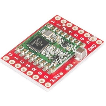 SparkFun RFM69 Breakout 434MHzSPARKFUN
¥4,398税込¥4,838
1個
33日以内出荷
DescriptionThis is the SparkFun RFM69 Breakout, a small piece of tech that breaks out all the pins available on the RFM69HCW module as well as making the transceiver easy to use. The RFM69HCW is an inexpensive and versatile radio module that operates in the unlicensed ISM(Industry, Science and Medicine)radio band. It's perfect for building inexpensive short-range wireless networks of sensors and actuators for home automation, citizen science and more.This RFM69HCW operates on the 434MHz frequency and is capable of transmitting at up to 100mW and up to 300kbps, but you can change both of those values to fit your application. For example, you can maximize range by increasing the transmit power and reducing the data rate, or you can reduce both for short-range sensor networks that sip battery power. At full power and with simple wire antennas, we can get messages from one side of a large office building to the other through numerous internal walls. In open air you can reach 500 meters or more. With more complex antennas and modulation schemes, similar parts have successfully transmitted from space to the ground(by very smart amateur radio enthusiasts; your mileage may vary)!The RFM69HCW uses an SPI(Serial Peripheral Interface)to communicate with a host microcontroller, and several good Arduino libraries are available. It supports up to 256 networks of 255 nodes per network, features AES encryption to keep your data private, and transmits data packets up to 66 bytes long.SparkFun sells two versions of the RFM69HCW:a 915MHz version and this 434MHz version. Although the ISM band is license-free, the band itself is different in different areas. Very roughly, 915MHz is for use in the Americas, and the 434MHz version is for use in Europe, Asia and Africa. Check your local regulations for other areas.Get Started with the RFM69HCW Hookup GuideFeaturesTransmit power:-18dBm(0.016mW)to +20dBm(100mW)in 1dBm stepsReceive sensitivity:down to -120dBm at 1.2kbpsModulation types:FSK GFSK MSK GMSK OOKBit rates(FSK):1.2kbps to 300kbpsVoltage range:1.8V to 3.6VCurrent consumption:0.1uA sleep, 1.25mA standby, 16mA receive, 130mA transmit(max)Encryption:AES 128-bit(optional)Packet buffer(FIFO):66 bytes0.8"×1.1"
アズワン品番67-0429-33
 Raspberry Pi Compute Module 3+ LiteSPARKFUN
¥10,980税込¥12,078
1個
33日以内出荷
DescriptionThe Raspberry Pi Compute Module 3+ Lite contains the guts of a Raspberry Pi 3 Model B+(the BCM2837 processor and 1GB LPDDR2 RAM). This module allows a designer to leverage the Raspberry Pi hardware and software stack in their own custom systems and form factors. In addition this module has extra IO interfaces over and above what is available on the Raspberry Pi model A/B boards, opening up more options for the designer.This is all integrated onto a small(67.6mm×31mm)board that fits into a standard DDR2 SODIMM connector. You get the full flexibility of the BCM2837 SoC(which means that many more GPIOs and interfaces are available than with a standard Raspberry Pi), and designing the Module into a custom system should be relatively straightforward because all the tricky bits have been put onto the Module itself.The CM3+ Lite product is the same as CM3+ except the eMMC Flash is not fitted, and the SD/eMMC interface pins are available for the user to connect their own SD/eMMC device. Note that the CM3+ is electrically identical and, with the exception of higher CPU z-height, physically identical to the legacy CM3 products.Note:The CM3+ modules require a software/firmware image dated November 2018 or newer to function correctly.FeaturesBroadcom BCM2837B0, Cortex-A53(ARMv8)64-bit SoC @ 1.2GHz1GB LPDDR2 SDRAMOperating Supply Voltage:1.8V, 3.3VMinimum Operating Temperature:-25CMaximum Operating Temperature:+80CHDMI, MIPI, USB, and GPIO interfaces on edge connector
アズワン品番67-0423-17
 SparkFun Qwiic Motor DriverSPARKFUN
¥6,698税込¥7,368
1個
欠品中
DescriptionThe SparkFun Qwiic Motor Driver takes all the great features of the Serial Controlled Motor Driver(SCMD)and miniaturizes them, adding Qwiic ports for plug and play functionality. Boasting the same 4245 PSOC and 2-channel motor ports as the SCMD, the SparkFun Qwiic Motor Driver is designed to communicate over I2C to make setting up your next robotic project as fast and easy as possible! Utilizing our handy Qwiic system and screw terminals for motor and power hook-up, no soldering is required to connect it to the rest of your system.With 1.2A steady state drive per channel(1.5A peak)and 127 levels of DC drive strength, this little Qwiic board is perfect for your small DC motor driver needs. Since the Qwiic Motor Driver is a 3.3V logic device, you'll need to use a logic level converter to interface to 5V.The I2C address of the Qwiic Motor Driver is 0x5D and is jumper selectable to 0x58, 0x59, 0x5A, 0x5B, ... 0x63.The SparkFun Qwiic Connect System is an ecosystem of I2C sensors, actuators, shields and cables that make prototyping faster and less prone to error. All Qwiic-enabled boards use a common 1mm pitch, 4-pin JST connector. This reduces the amount of required PCB space, and polarized connections mean you can't hook it up wrong.Need a custom board? This component can be found in SparkFun's A La Carte board builder. You can have a custom design fabricated with this component - and your choice of hundreds of other sensors, actuators and wireless devices - delivered to you in just a few weeks.Get Started With the Qwiic Motor Driver Hookup GuideFeatures1.5 A peak drive per channel, 1.2 A steady stateOperates from 3 to 11 Volts with 12V absolute max3.3V default VCC and logic127 levels of DC drive strength.Controllable by I2C or TTL UART signalsDirection inversion on a per motor basisGlobal Drive enableExposed small heat sink shapeSeveral I2C addresses, default UART bauds availableAdjustable I2C Address:0x5D Default2x Qwiic ConnectorsDocumentsSchematicEagle FilesBoard DimensionsHookup GuideArduino LibraryPython ModuleGithub Hardware Repo
アズワン品番67-0426-33
 SparkFun RTK SurveyorSPARKFUN
¥129,800税込¥142,780
1個
33日以内出荷
DescriptionThe SparkFun RTK Surveyor is an easy to use GNSS receiver for centimeter-level positioning. Perfect for surveying, this preprogrammed device can also be used for autonomous driving, navigation, asset tracking and any other application where there is a clear view of the sky. The RTK Surveyor can also be used as a base station. With the flick of a switch, two RTK Surveyors can be used to create an RTK system capable of 14mm horizontal positional accuracy. The built-in Bluetooth(R)connection via an ESP32 WROOM enables the user to use the RTK Surveyor with their choice of GIS application on a phone or tablet. The built in battery allows field use for up to four hours and is compatible with common USB battery banks.This device can be used in four modes:GNSS Positioning(~30cm accuracy)GNSS Positioning with RTK(1.4cm accuracy)GNSS Base StationGNSS Base Station NTRIP ServerIn Position mode the device receives L1/L2 signals from a user-provided antenna and the high-grade GNSS receiver provides lat/long and altitude with accuracies around 300mm.In Positioning with RTK mode the device receives L1/L2 signals from the antenna and correction data from a base station. The correction data can be obtained from a cellular link to online correction sources or over a radio link to a 2nd RTK Surveyor setup as a base station.In Base Station mode the device is mounted to a temporary position(like a tripod)and begins transmitting correction data over a radio or internet connection. A base is often used in conjunction with a second unit set to 'Positioning with RTK' to obtain the 14mm relative accuracy.In Base Station NTRIP Server mode the device is mounted to a semi or permanently fixed position(like a roof)and connects over WiFi to transmit the correction data to a NTRIP caster so that any rover can access the correction data over a cellular or internet connection. This type of base is a very easy way to setup a very precise absolute correction source.Two cables are provided with the RTK Surveyor allowing a user to plug on our easy to use Serial Telemetry Radios or their own radio link. If a local correction source is within 10km, a user can also use their phone to provide correction data over the Bluetooth(R)link(no external radio needed!).Note:The SparkFun RTK Surveyor is just the enclosed device and does NOT include an antenna, serial telemetry radio, or associated mounting pieces. These items will need to be purchased separately from the Hookup Accessories below.Get Started With the SparkFun RTK Surveyor GuideFeaturesGNSS Receiver:ZED-F9PConcurrent reception of GPS, GLONASS, Galileo and BeiDouReceives both L1C/A and L2C bandsCurrent:68mA - 130mA(varies with constellations and tracking state)Time to First Fix:25s(cold), 2s(hot)Max Navigation Rate:PVT(basic location over UBX binary protocol)- 25HzRTK - 20HzRaw - 25HzHorizontal Position Accuracy:2.5m without RTK0.010m with RTKMax Altitude:50km(31 miles)Max Velocity:500m/s(1118mph)Bluetooth(R)Transceiver:ESP32 WROOMXtensa(R)dual-core 32-bit LX6 microprocessorUp to 240MHz clock frequency16MB of flash storage520kB internal SRAMIntegrated 802.11 BGN WiFi transceiverIntegrated dual-mode Bluetooth(R)(classic and BLE)Hardware accelerated encryption(AES, SHA2, ECC, RSA-4096)2.5 μA deep sleep currentOverall DeviceInternal Battery:LiPo 1000mAh with 500mA chargingRadio Port:3.3V TTL Serial(57600bps RTCM TX/RX)Data Port:3.3V TTL Serial(115200bps NMEA)Weight:132g(entire device including battery)Dimensions:118mm×79mm×30mm(4.7in×3.1in×1.2in)1x Qwiic Connector1x microSD Socket for optional loggingChanges:This version(which replaces SPX-17369)uses a reinforced edge mount SMA connector for better resiliency when a fixed 'stub' antenna is used.
アズワン品番67-0423-95