カテゴリ
- 学童・教育用品(24)
- 制御機器(1)
- 科学研究・開発用品(1)
絞り込み
ブランド
- SPARKFUN
- エレコム(22)
- GPR Exhaust (ジーピーアールエキゾースト)(160)
- メディアカバーマーケット(157)
- 三菱ふそう(39)
- piaggio(ピアッジオグループ)(19)
- ラスタバナナ(17)
- AOHI(アオハイ)(14)
- ハイテクインター(12)
- DHA Corporation(12)
- BAGSTER (バグスター)(11)
- DUCATI(11)
- Ringfeder(10)
- KTM(7)
- bitstrong(7)
- ホンダ(6)
- 日野自動車(5)
- SIEMENS(5)
- イノマタ化学(4)
- ブランドをもっと見る
「oppo」の検索結果
 Poke Home Connector - 2-PinSPARKFUN
¥189税込¥208
1個
33日以内出荷
DescriptionPoke Home Connectors have been featured on a number of our boards over the last few years by providing a simple screw-terminal-type connector for easy wire connection purposes. Similar to screw terminals, Poke Home Connectors grasp a wire entered into the receiving area of the pin-out by pressing down on the small plastic strip at the end of the housing. Doing so raises the internal clamp and, upon release of the button secures the wire in place without any soldering required.Poke Home Connectors work better in environments with a lot of vibrations(i.e. automotive applications)or when a wire is expanding or contracting due to temperature cycling. Additionally, the tension in the connector is automatically adjusted to the wire gauge(assuming it is within the accepted wire thickness)as opposed to variances in tension when a user tightens the screw terminal.
アズワン品番67-0425-83
 SparkFun FTDI Starter Kit - 3.3VSPARKFUN
¥5,998税込¥6,598
1個
33日以内出荷
DescriptionThe SparkFun 3.3V FTDI Starter Kit gives you just what you need to get started with FTDI FT232RL USB to serial IC. The pinout of the included board matches the FTDI cable standard to work with official Arduino and cloned 3.3V Arduino boards. It can also be used for general serial applications. The major difference with this board is that it brings out the DTR pin as opposed to the RTS pin of the FTDI cable. The DTR pin allows an Arduino target to auto-reset when a new Sketch is downloaded. This is a really nice feature to have and allows a sketch to be downloaded without having to hit the reset button. This board will auto reset any Arduino board that has the reset pin brought out to a 6-pin connector.The SparkFun FTDI Basic Breakout was designed to decrease the cost of Arduino development and increase ease of use(the auto-reset feature rocks!). Our Arduino Pro and LilyPad boards use this type of connector.The included cable is a USB 2.0 type B to Mini-B 5-pin black cable.
アズワン品番67-0424-75
 Hamburger Mini SpeakerSPARKFUN
¥1,998税込¥2,198
1個
欠品中
DescriptionThis will be a treat for your ears! The Hamburger Mini Speaker is a 3W economical speaker option for any project needing stand-alone sound. The Hamburger features a built-in lithium polymer battery for portable application, a 3.5mm stereo jack(sorry, iPhone 7 users)and two volume options(quiet and loud)to control how loud your sound needs to be. This speaker really can't be compared to a good pair of JBLs, but for the price point the Hamburger won't break the bank for your next audiophile project!Why call it the Hamburger? When you twist the top and bottom halves of the speaker in opposite directions, it expands out like an accordion extending the bass reflex portion. Each Hamburger Mini Speaker comes with a 1.5ft mini USB cable for recharging capabilities.We use this amplified speaker quite frequently with our Spectacle Audio Board and Sound Kit, but that doesn't mean you can't find a different use for it!FeaturesSpeaker:3W(1KHz, THD10%)36mmFrequency Response:20Hz~20KHzS/N ratio:≧85dBABuilt-in 3.7V 180mA LiPo battery~1--2 hour play time52mm x 38mm
アズワン品番67-0420-93
 SparkFun FT231X BreakoutSPARKFUN
¥4,598税込¥5,058
1個
33日以内出荷
DescriptionIntroducing the SparkFun FT231X Breakout board, complete with the full UART hardware handshake feature! The pin-out of this board matches the FTDI cable to work with official Arduino and cloned Arduino boards. It can also be used for general serial applications.This board still brings out the DTR pin as opposed to the RTS pin of the FTDI cable. The DTR pin allows an Arduino target to auto-reset when a new Sketch is downloaded. This is a really nice feature to have and allows a sketch to be downloaded without having to hit the reset button. This board will auto-reset any Arduino board that has the reset pin brought out to a 6-pin connector.The coolest thing about the FT231X Breakout is that we have broken out ALL the pins for your use, making this board all the more hackable! It also uses a common microUSB jack.One of the features of this board is a jumper on the back, which allows the VCC output to be configured to either 3.3V or 5V. This board ships default to 5V, but you can cut the default trace and add a solder jumper if you need to switch to 3.3V. It should be noted that the max input of the FT231X is only 3.3V, but it can operate down to 1.8V with external pull-ups and is also 5V tolerant.
アズワン品番67-0419-85
 LilyPad LilyMini ProtoSnapSPARKFUN
¥5,998税込¥6,598
1個
33日以内出荷
DescriptionThe LilyMini ProtoSnap is a great way to get started learning about creating interactive e-textile circuits before you start sewing. Like other LilyPad ProtoSnap boards, the LilyMini ProtoSnap has all of its pieces wired together out of the box, enabling you to test the circuit's function before you sew. At the center of the board is a pre-programmed LilyMini microcontroller connected to a LilyPad Light Sensor, LilyPad Button and two pairs of LilyPad LEDs.The LilyMini ProtoSnap ships with pre-loaded code that uses all the LilyPad pieces connected to it. This sample code has three modes, which can be selected by pressing the LilyPad Button on the bottom-left side of the ProtoSnap. The built-in RGB LED on the LilyMini will change color to indicate which mode has been selected:White:All LEDs on.Magenta:LEDs fade in and out in a breathing pattern. When the light sensor is covered, LEDs fade faster.Cyan:LEDs off. When the light sensor is covered, LEDs will twinkle.The LilyMini board, at the center of the ProtoSnap, has a built-in battery holder for a CR2032 battery(included). On the opposite side of the LilyMini you will find the SAMD11 brain, which controls the ProtoSnap.Note:A portion of this sale is given back to Dr. Leah Buechley for continued development and education in e-textiles.Note:The LilyPad LilyMini ProtoSnap does NOT include sewing needles or conductive thread. These items will need to purchased separately.Warning:You cannot reprogram this product and any attempt at programming is at your own risk!Get Started with the LilyMini ProtoSnap Guide
アズワン品番67-0422-40
 One-Wire Ambient Temperature Sensor - MAX31820SPARKFUN
¥1,598税込¥1,758
1個
33日以内出荷
DescriptionThe MAX31820 ambient temperature sensor provides 9-bit to 12-bit Celsius temperature measurements with ±0.5℃ accuracy over a +10℃ to +45℃ temperature range. Over its entire -55℃ to +125℃ operating range, the device has ±2.0℃ accuracy.The device communicates over a one-wire bus that, by definition, requires only one data line(and ground)for communication with a central microprocessor. In addition, the device can derive power directly from the data line, eliminating the need for an external power supply. Requiring so few pins enables the device to be placed in a 3-pin TO-92 package. The form factor of this package allows the device to be placed above the board and thus measure the ambient temperature of a system, as opposed to the board temperature that a surface-mount package would measure.Each MAX31820 has a unique 64-bit serial code, which allows multiple MAX31820 devices to function on the same one-wire bus. Therefore, it is simple to use one microprocessor to control many devices distributed over a large area.FeaturesUnique one-wire interface requires only one port pin for communicationEach device has a unique 64-bit serial code stored in onboard ROMMultidrop capability simplifies distributed temperature-sensing applicationsRequires no external componentsCan be powered from data line; 3.0V to 3.7V power-supply rangeMeasures temperatures from -55℃ to +125℃±0.5℃ accuracy from +10℃ to +45℃Thermometer resolution is user-selectable from 9 bits to 12 bitsConverts temperature to 12-bit digital word in 750ms(Max)User-definable nonvolatile(NV)alarm settingsAlarm search command identifies and addresses devices whose temperature is outside programmed limits(Temperature Alarm Condition)Available in 3-pin TO-92 packageTO-92 package allows measurement of ambient temperatureSoftware compatible with the DS1822 and DS18B20
アズワン品番67-0426-62
 SparkFun Thermocouple Breakout - MAX31855KSPARKFUN
¥6,198税込¥6,818
1個
33日以内出荷
DescriptionThe SparkFun MAX31855K Thermocouple Breakout is a simple 14-bit resolution, SPI-compatible, serial interface thermocouple digitizer that makes reading a wide range of temperatures possible. A thermocouple works by taking two wires made of dissimilar metals, connecting them at the two ends, and making a temperature gradient between one end and the other(a 'hot' end and a 'cold' one). Once this is achieved, a voltage potential is formed and current flows. The SparkFun Thermocouple Breakout takes a standard Type-K thermocouple in one end, digitizes the temperature measured and sends that data out the other end via a SPI interface, thereby interpreting the data and translating it for you to read!With the SparkFun Thermocouple Breakout, the thermocouple's hot junction can be read from -200℃ to +700℃ with an accuracy of ±2℃ while the cold junction, inside the MAX31855K, can only range from -20℃ to +85℃ while maintaining ±2℃ accuracy. The MAX31855K constantly measures the temperature of the cold junction using an internal temperature-sensing diode. The MAX31855K requires a power source from +3.0V to +3.6V(+3.0V nominal)and only draws 1.5mA maximum.The Thermocouple Breakout is designed to accept a standard thermocouple connector, for convenience and compatibility with probes you may already own. These connectors aren't necessary, and you could solder a thermocouple directly into the through-holes labeled '+' and '-'. If you decide to solder the thermocouple directly to the breakout board, it is recommended that the thermocouple be mounted for strain relief to avoid breaking the thin wires. Notches for a zip-tie or wire wrapping have been provided in the PCB opposite the header for this purpose.Features14-bit ResolutionSPI-Compatible, Serial Interface-200℃ to +700℃ Temperature Reading with ±2℃ Accuracy3.0V to 3.6V(+3.0V nominal)RequiredAccepts Type-K Thermocouple
アズワン品番67-0426-49
 SparkFun Beefy 3 - FTDI Basic BreakoutSPARKFUN
¥5,798税込¥6,378
1個
33日以内出荷
DescriptionThis is SparkFun Beefy 3 FTDI Basic Breakout for the FTDI FT231X USB to serial IC. The pinout of this board matches the FTDI cable to work with official Arduino and cloned 3.3V Arduino boards. It can also be used for general serial applications. Built upon the same foundation as our 3.3V SparkFun FTDI Basic Breakout, the Beefy 3 is equipped with an AP2112K voltage regulator making this FTDI basic breakout board capable of handling a current load of up to 600 mA! With the addition of a more "Beefy" voltage regulator your will now be able to power a 3.3V project directly from the FTDI. The pinout of this board matches the FTDI cable to work with official Arduino and cloned 3.3V Arduino boards.This board brings out the DTR pin as opposed to the RTS pin of the FTDI cable. The DTR pin allows an Arduino target to auto-reset when a new Sketch is downloaded. This is a really nice feature to have and allows a sketch to be downloaded without having to hit the reset button. This board will auto reset any Arduino board that has the reset pin brought out to a 6-pin connector. The pins labeled BLK and GRN correspond to the colored wires on the FTDI cable. The black wire on the FTDI cable is GND, green is DTR. Use these BLK and GRN pins to align the FTDI basic board with your Arduino target.There are pros and cons to the FTDI Cable vs the FTDI Basic. This board has TX and RX LEDs that allow you to actually see serial traffic on the LEDs to verify if the board is working, however this board now requires a Micro-B USB cable. The FTDI Cable is well protected against the elements, but is large and cannot be embedded into a project as easily. The FTDI Basic uses DTR to cause a hardware reset where the FTDI cable uses the RTS signal.This board was designed to decrease the cost of Arduino development and increase ease of use(the auto-reset feature rocks!). Our Arduino Pro and LilyPad boards use this type of connector.
アズワン品番67-0430-06
 LIDAR-Lite v3HPSPARKFUN
¥39,980税込¥43,978
1個
33日以内出荷
DescriptionLIDAR has never looked so good! This is the LIDAR-Lite v3HP, a compact, high-performance optical distance measurement sensor from Garmin(TM). The LIDAR-Lite v3HP istheideal optical ranging solution for drone, robot, or unmanned vehicle applications. Each sensor is housed in a durable, IPX7-rated housing and includes all the core features and user configurability of the popular LIDAR-Lite v3.The v3HP is very similar in function to that of the v3 but it can now sample faster at rates greater than 1kHz(where as the v3 is only capable of up to 500Hz). Another improvement is that this v3HP model is more power efficient with current consumption rates 40mA less than the v3(that's 65mA as opposed to 105mA while idle, and 85mA instead of 130mA while acquiring).Each LIDAR-Lite v3HP has a range of 1m to 40m and features an edge-emitting, 905nm(1.3 watts), single-stripe laser transmitter, 8m Radian beam divergence, and an optical aperture of 12.5mm. This version of the LIDAR-Lite still operates at 5VDC(6V max)with a peak power of 1.3W and still possesses an accuracy of +/- 2.5cm at >2m. On top of everything else, the LIDAR-Lite is user-configurable, allowing adjustment between accuracy, operating range and measurement time and can be interfaced via I2C or PWM with the attached 200mm cable.Note:CLASS 1 LASER PRODUCT CLASSIFIED EN/IEC 60825-1 2014. This product is in conformity with performance standards for laser products under 21 CFR 1040, except with respect to those characteristics authorized by Variance Number FDA-2016-V-2943 effective September 27, 2016.Get Started with the LIDAR-Lite v3HP GuideFeaturesResolution:1 cmTypical accuracy:+/- 2.5cm at distances greater than 2 meters(Refer to operating manual for complete operating specifications)Range:1m to 40mUpdate rate:Greater than 1kHzInterface:I2C or PWMPower(operating voltage):4.75-5VDC; 6V MaxCurrent consumption:65ma idle; 85ma during acquisitionOperating temperature:-20℃ to 60℃Laser wave length/Peak power:905nm/1.3WBeam divergence:8m RadianOptical aperture:12.5mmWater rating:IPX7Unit dimensions:24.5mm×53.5mm×33.5mm(1.0in×2.1in×1.3in)Weight:34g(1.2oz)
アズワン品番67-0426-76
 SparkFun OpenLog with HeadersSPARKFUN
¥6,898税込¥7,588
1個
欠品中
DescriptionThe SparkFun OpenLog with Headers is an open source data logger that works over a simple serial connection and supports microSD cards up to 64GB. The OpenLog can store or "log" huge amounts of serial data and act as a black box of sorts to store all the serial data that your project generates, for scientific or debugging purposes. This version of th OpenLog even includes pre-soldered headers for your convenience.The SparkFun OpenLog uses an ATmega328 running at 16MHz thanks to the onboard resonator. The OpenLog draws approximately 2-3mA in idle(nothing to record)mode. During a full record OpenLog can draw 10 to 20mA depending on the microSD card being used.All data logged by the OpenLog is stored on the microSD card. Any 512MB to 32GB microSD card should work. OpenLog supports both FAT16 and FAT32 SD formats.For even better performance the OpenLog Artemis is the tool you need, featuring logging speeds up to 500000bps.Get Started with the SparkFun OpenLog GuideFeaturesVCC Input:3.3V-12V(Recommended 3.3V-5V)Log to low-cost microSD FAT16/32 cards up to 32GBSimple command interfaceConfigurable baud rates(up to 115200bps)Preprogrammed ATmega328 and bootloaderFour SPI pogo pinsTwo LEDs indicate writing status2mA idle, 6mA at maximum recording ratePre-soldered Headers
アズワン品番67-0422-30
 SparkFun ProDriver - Stepper Motor Driver TC78H670FTGSPARKFUN
¥6,398税込¥7,038
1個
33日以内出荷
DescriptionThe SparkFun ProDriver makes it easy to start developing with the TC78H670FTG bipolar stepper motor driver from Toshiba! Latch terminals provide instant solder-less connections to every feature offered. Use our extensive Arduino Library w
アズワン品番67-0426-39
 SparkFun Multiplexer Breakout - 8 Channel 74HC4051SPARKFUN
¥999税込¥1,099
1個
33日以内出荷
DescriptionThe SparkFun Multiplexer Breakout provides access to all pins and features of the 74HC4051, an 8-channel analog multiplexer/demultiplexer. The 74HC4051 allows you to turn four I/O pins into eight multifunctional, individually selectable signals, which can be used to do everything from driving eight LEDs to monitoring eight potentiometers.The 74HC4051 can function as either a multiplexer or a demultiplexer, and it features eight channels of selectable inputs/outputs. The routing of common signal to independent I/O is set by digitally controlling three select lines, which can be set either high or low into one of eight binary combinations.One half of the board breaks out the control signals(E, S0-S2)and common input/output(Z). The other side provides access to all eight independent I/O's(Y0-Y7). Both sides include supply and ground connections(VCC, VEE, GND).Get Started with the 74HC4051 Breakout GuideFeaturesSwitches analog or digital signals8 channels controlled by 3 select inputsWide voltage supply range:2 -- 10VBipolar supply support(e.g., ±5V)Optional enable inputBreadboard compatible breakout
アズワン品番67-0419-95
 Copper Tape - Conductive Adhesive, 2" 50ftSPARKFUN
¥9,298税込¥10,228
1個
欠品中
DescriptionCopper tape has countless applications in electronics from creating low-profile traces for electrical components to RF-shielding and antenna-making. Copper tape is even used to join things together using solder, like the stained glass on Tiffany lamps.This copper tape is backed by a conductive adhesive, is a whopping 2" wide, and comes in rolls of 50 feet. That's a lot of copper.
アズワン品番67-0425-18
 Himax CMOS Imaging Camera - HM01B0SPARKFUN
¥3,698税込¥4,068
1個
33日以内出荷
DescriptionThe HM01B0 from Himax Imaging is an ultra low power CMOS Monochrome Image Sensor that enables the integration of an "Always On" camera for computer vision applications such as gestures, intelligent ambient light and proximity sensing, tracking and object identification. The sensor allows the sensor to consume very low power of <2mW at QVGA 30FPS. This low power consumption and vision applications camera comes with a ribbon cable that mates to the camera connector populated on the following products:MicroMod Machine Learning Carrier BoardArtemis Development KitEdge Development Board - Apollo3 BlueThe HM01B0 contains 320×320 pixel resolution and supports a 320×240 window mode which can be readout at a maximum frame rate of 60FPS, and a 2×2 monochrome binning mode with a maximum frame rate of 120FPS. The video data is transferred over a configurable 1bit, 4bit or 8bit interface with support for frame and line synchronization. The sensor integrates black level calibration circuit, automatic exposure and gain control loop, self-oscillator and motion detection circuit with interrupt output to reduce host computation and commands to the sensor to optimize the system power consumption.FeaturesImage SensorUltra Low Power Image Sensor(ULPIS)designed for Always On vision devices and applicationsHigh sensitivity 3.6μ BrightSenseTM pixel technology320×320 active pixel resolution with support for QVGA window, vertical flip and horizontal mirror readoutProgrammable black level calibration target, frame size, frame rate, exposure, analog gain(up to 8x)and digital gain(up to 4x)Automatic exposure and gain control loop with support for 50 / 60Hz flicker avoidanceFlexible 1bit, 4bit and 8bit video data interface with video frame and line syncMotion Detection circuit with programmable ROI and detection threshold with digital output to serve as an interruptOn-chip self oscillatorI2C 2-wire serial interface for register accessHigh CRA for low profile module designSensor ParametersActive Pixel Array 320×320Pixel Size 3.6 μm×3.6 μmFull Image Area 1152 μm×1152 μmDiagonal(Optical Format)1.63 mm(1/11″)Scan Mode:ProgressiveShutter Type:Electronic Rolling ShutterFrame Rate MAX 51 fps @ 320×320, 60 fps @ 320×240(QVGA)CRA(maximum)30℃Sensor SpecificationsSupply Voltage:Analog - 2.8 V, Digital - 1.5V(Internal LDO:1.5V - 2.8V), I/O - 1.5 - 2.8VInput Reference Clock:3 - 50 MHzSerial Interface(I2C):2-wire, 400 KHz max.Video Data Interface:1b, 4b, 8b with frame / line SYNCOutput Clock Rate MAX:50 MHz for 1bit, 12.5 MHz for 4bit, 6.25 MHz for 8bitEst. Power Consumption(include IO with 5pF load):QVGA 60FPS(Typical)<4 mWQVGA 30FPS(Typical)<2 mW
アズワン品番67-0427-08
 Alchitry Cu FPGA Development Board Lattice iCE40 HXSPARKFUN
¥15,980税込¥17,578
1個
33日以内出荷
DescriptionIf you are not needing a lot of power to start your FPGA adventure, or are looking for a more economical option, the Alchitry Cu FPGA Development Board might be the perfect option for you! The Alchitry Cu is a "lighter" FPGA version than the Alchitry Au but still offers something completely unique. FPGAs, or Field-Programmable Gate Arrays, are an advanced development board type for engineers and hobbyists alike to experience the next step in programming with electronics. The Cu truly exemplifies the trend of more affordable and increasingly powerful FPGA boards arriving each year. This board is a fantastic starting point into the world of FPGAs and the heart of your next project. Finally, now that this board is built by SparkFun, we added a Qwiic connector for easy I2C integration!The Alchitry Cu uses the Lattice iCE40 HX FPGA with 7680 logic cells and is supported by the open source tool chain Project IceStorm. The Cu possesses 79 IO pins with eight general purpose LEDs; a 100MHz on-board clock that can be manipulated internally by the FPGA; a USB-C connector to configure and power the board; and a USB to serial interface for data transfer.By adding stackable expansion boards similar to shields or HATs called "Elements," the Alchitry Cu is able to expand its own hardware capabilities by adding prototyping spaces, buttons, LEDs, and more!The SparkFun Qwiic Connect System is an ecosystem of I2C sensors, actuators, shields and cables that make prototyping faster and less prone to error. All Qwiic-enabled boards use a common 1mm pitch, 4-pin JST connector. This reduces the amount of required PCB space, and polarized connections mean you can't hook it up wrong.Get Started with our Learning FPGA TutorialsFeaturesLattice iCE40-HX8K FPGA - 7680 logic elements79 IO pins(3.3V logic level)USB-C to configure and power the boardEight general purpose LEDsOne button(typically used as a reset)100MHz on-board clock(can be multiplied internally by the FPGA)Powered with 5V through USB-C port, 0.1" holes, or headersUSB to serial interface for data transfer(up to 12Mbaud)Qwiic ConnectorDimensions of 65mm×45mmExamplesFirst FPGA Project - Getting Fancy with PWMExternal IO and Metastability
アズワン品番67-0423-08
 Shapeoko 4 XL - Hybrid Table, with RouterSPARKFUN
¥799,800税込¥879,780
1個
33日以内出荷
DescriptionPlease note, these machines are built to order have an estimated lead time of 4 business days before shippingThis is the Shapeoko 4 XL, nearly double the cutting area of the Shapeoko 4 Standard! The Shapeoko is a 3-axis CNC Machine kit that allows you to create your 2D and 3D designs out of non-ferrous metals, hardwoods, and plastics. The Shapeoko 4 XL is designed to be affordable enough for any shop and powerful enough to do real work. Don't let the size intimidate you! This is an entry-level CNC machine designed for hobbyists, artists, and fabricators!Each Shapeoko 4 XL has a cutting area of 838.2mm(X)x 444.5 mm(Y)x 101.6mm(Z)(33"×17.5"×4")and an overall footprint of 1270mm(X)x 609.6mm(Y)x 482.6mm(Z)(50"×24"×19"). The power cable included in this kit is designed for the United States National Plug Standard. Don't forget you can put whatever you want on the adapter ring(as long as it fits), whether that's a laser, 3D print extrusion head, or a marker. Get creative!Upgrades from the Shapeoko 3 include:New, more rigid v-wheel design15mm beltsInductive homing switchesNew electronicsIntegrated t-slot Hybrid Table(OPTIONAL)Fully-supported Y extrusionsLeadscrew-driven Z-axisNew, more rigid 65mm router mountSweepy 65mm V2 dust bootNote:This item is non-returnable. If this item arrives damaged or is not functioning properly, please do not hesitate to contact us to see if further actions may be taken.Not Compatible with the Shapeoko 4:Expansion PacksT-Track Clamp KitsZ-PlusProximity Switch KitMaintenance KitShapeoko 3 Bit SetterHDZ 4.0FeaturesFootprint:1270mm×609.6mm×482.6mm(50"×24"×19")Cutting Area:838.2mm×444.5mm×101.6mm(33"×17.5"×4")Weight 137lbs.Operating System:Mac(OSX 10.14 or higher)or PC(Windows 8.1 or 10, Intel or AMD)
アズワン品番67-0428-90
 SparkFun Wireless Joystick KitSPARKFUN
¥13,980税込¥15,378
1個
33日以内出荷
DescriptionThe SparkFun Wireless Joystick Kit provides an easy way to control your next XBee project. Before the wireless joystick, radio-controlled projects used hobby RC transmitters, the same ones used for RC cars, boats and planes. The problem with these transmitters is that many aren't customizable, and the ones that are tend to be too expensive for many of us. The Wireless Joystick Kit offers a custom wireless solution for those who want to control their project their own way.Equipped with the increasingly popular SAMD21 onboard, all you need is to assemble the SparkFun Wireless Joystick into the configuration you want and add your own XBee and lithium ion battery into the provided sockets. The Wireless Joystick Kit can be assembled into a configuration that utilizes dual joysticks for better RC steering robots(like tanks)or a single joystick configuration with four 12mm momentary pushbuttons(a setup similar to what older game consoles used). We have provided a full Hookup Guide that gives assembly instructions, as well as a tank-steering motor controller tutorial to help get you started!Please be aware that the SparkFun Wireless Joystick Kit isNOT supported on Windows 7/8due to a lack of support drivers for those specific OS's.Note:This kit will need to be assembled before use, so a beginner's knowledge of soldering will be required. Additionally, in an effort to keep shipping rates down and make this kit available to people throughout the world without delay, there is no XBee or lithium ion battery included.Get Started with the Wireless Joystick Kit Guide
アズワン品番67-0424-08
 Load Cell - 200kg, S-Type TAS501SPARKFUN
¥29,980税込¥32,978
1個
欠品中
DescriptionThis S-Type load cell(sometimes called a strain gauge)can translate up to 200kg of pressure(force)into an electrical signal. Each load cell is able to measure the electrical resistance that changes in response and proportion to the strain(e.g., pressure or force)applied to the form. With this gauge you will be able to tell just how heavy an object is, if an object's weight changes over time, or if you simply need to sense the presence of an object by measuring strain or load applied to a surface.Each straight bar load cell is made from an alloy steel and is capable of reading a capacity up to 200kg. These load cells have four strain gauges that are hooked up in a Wheatstone bridge formation. The color code on the wiring is as follows:red = E+, green = O+, black = E-, and white = O-. Additionally, these load cells offer an IP66 protection rating and feature two M4 and two M5 sized through-holes for mounting purposes.Get Started with the Load Cell GuideFeatures51mm×19mm×76mm, 3m Wire
アズワン品番67-0426-66
 Load Cell - 10kg, Straight Bar TAL220SPARKFUN
¥3,998税込¥4,398
1個
欠品中
DescriptionThis straight bar load cell(sometimes called a strain gauge)can translate up to 10kg of pressure(force)into an electrical signal. Each load cell is able to measure the electrical resistance that changes in response to, and proportional of, the strain(e.g. pressure or force)applied to the bar. With this gauge you will be able to tell just how heavy an object is, if an object's weight changes over time, or if you simply need to sense the presence of an object by measuring strain or load applied to a surface.Each straight bar load cell is made from an aluminum-alloy and is capable of reading a capacity of 10kg. These load cells have four strain gauges that are hooked up in a wheatstone bridge formation. The color code on the wiring is as follows:red = E+, green = O+, black = E-, and white = O-. Additionally, these load cells offer an IP66 protection rating and feature two M4 and two M5 sized through-holes for mounting purposes.Get Started with the Load Cell GuideFeatures80mm×12.7mm×12.7mm, 250mm Wire
アズワン品番67-0426-52
 SparkFun Configurable OpAmp Board - TSH82SPARKFUN
¥2,298税込¥2,528
1個
欠品中
DescriptionThe SparkFun TSH82 Configurable OpAmp Board was designed to give you the best combination of performance and flexibility that we could achieve by giving you two gain stages, each one independently accessible on the header pins. Each stage is natively configured as an inverting amplifier that can also be strung together to expand the capabilities of the TSH82 from STMicroelectronics. With the use of the jumpers on the back of the board, you can configure each stage for non-inverting operation, differential input, and DC input coupling.Electrically speaking, both stages on this board are identical. The default configuration is inverting with a gain of -4.7 with a bandwidth of almost 10MHz. Input signals are AC coupled, possess an input impedance of 10K with a low frequency cutoff of 15.9Hz. Outputs are also DC coupled, so don't forget to add a capacitor to the output if you're running a single-ended supply and need to strip out the DC component. The board will also operate with a single-ended DC power supply of 4.5V to 12V, or a bipolar supply from +/-2.25V to +/-6V.On the back of the board you'll find 10 solder jumpers that can be used to change the board's performance, but nothing there needs to be changed to use it in it's default state.Get Started With the Configurable OpAmp Board Guide
アズワン品番67-0420-03
 Load Cell - 5kg, Straight Bar TAL220BSPARKFUN
¥5,498税込¥6,048
1個
欠品中
DescriptionThis straight bar load cell(sometimes called a strain gauge)can translate up to 5kg of pressure(force)into an electrical signal. Each load cell is able to measure the electrical resistance that changes in response to, and proportional of, the strain(e.g. pressure or force)applied to the bar. With this gauge you will be able to tell just how heavy an object is, if an object's weight changes over time, or if you simply need to sense the presence of an object by measuring strain or load applied to a surface.Each straight bar load cell is made from an aluminum-alloy and is capable of reading a capacity of 5kg. These load cells have four strain gauges that are hooked up in a wheatstone bridge formation. The color code on the wiring is as follows:red = Exc+, green = Sig+, black = Exc-, and white = Sig-. Additionally, these load cells offer an IP65 protection rating and features two M5 sized through-holes for mounting purposes.Get Started with the Load Cell GuideFeaturesCapacity:5kgMaterial:Aluminum-AlloyParallel Beam TypeIP65 Rating55mm×12.7mm×12.7mm, 200mm Wire
アズワン品番67-0426-84
 SparkFun Thing Plus - RP2040SPARKFUN
¥6,698税込¥7,368
1個
33日以内出荷
DescriptionThe SparkFun Thing Plus - RP2040 is a low-cost, high performance board with flexible digital interfaces featuring the Raspberry Pi Foundation's RP2040 microcontroller. Besides the Thing Plus orFeatherfootprint(with 18 GPIO pins), the board also includes an SD card slot, 16MB(128Mbit)flash memory, a JST single cell battery connector(with a charging circuit and fuel gauge sensor), an addressable WS2812 RGB LED, JTAG PTH pins, four(4-40 screw)mounting holes, and our signature Qwiic connector.The RP2040 contains two ARM Cortex-M0+ processors(up to 133MHz)and features:264kB of embedded SRAM in six banks6 dedicated IO for SPI Flash(supporting XIP)30 multifunction GPIO:Dedicated hardware for commonly used peripheralsProgrammable IO for extended peripheral supportFour 12-bit ADC channels with internal temperature sensor(up to 0.5 MSa/s)USB 1.1 Host/Device functionalityThe RP2040 is supported with both C/C++ and MicroPython cross-platform development environments, including easy access to runtime debugging. It has UF2 boot and floating-point routines baked into the chip. While the chip has a large amount of internal RAM, the board includes an additional 16MB of external QSPI flash memory to store program code.The SparkFun Qwiic Connect System is an ecosystem of I2C sensors, actuators, shields and cables that make prototyping faster and less prone to error. All Qwiic-enabled boards use a common 1mm pitch, 4-pin JST connector. This reduces the amount of required PCB space, and polarized connections mean you can't hook it up wrong.Get Started With the Thing Plus RP2040 Hookup GuideFeaturesSparkFun Thing Plus - RP2040 FeaturesRaspberry Pi Foundation's RP2040 microcontroller16MB QSPI Flash MemoryJTAG PTH PinsThing Plus(or Feather)Form-Factor:18[1]x Multifunctional GPIO Pins[2]Four available 12-bit ADC channels with internal temperature sensor(500kSa/s)Up to eight 2-channel PWMUp to two UARTsUp to two I2C busesUp to two SPI busesUSB-C Connector:USB 1.1 Host/Device functionality2-pin JST Connector for a LiPo Battery(not included)500mA charging circuitQwiic ConnectorButtons:BootResetLEDs:PWR- Red 3.3V power indicatorCHG- Yellow battery charging indicator25- Blue status/test LED(GPIO 25)WS2812- Addressable RGB LED(GPIO 08)Four Mounting Holes:4-40 screw compatibleDimensions:2.3"×0.9"RP2040 General FeaturesDual Cortex M0+ processors, up to 133 MHz264 kB of embedded SRAM in 6 banks6 dedicated IO for QSPI flash, supporting execute in place(XIP)30 programmable IO for extended peripheral supportSWD interfaceTimer with 4 alarmsReal time counter(RTC)USB 1.1 Host/Device functionalitySupported programming languagesMicroPythonC/C++1.Note:GPIO 08is not included in this count, as it passes through the WS2812 addressable RGB LED first.GPIO 07andGPIO 23are counted as a single GPIO because they are tied together.2.Note:The GPIO pins are programmable so you can reconfigure the pins! Check out the RP2040 datasheet for more information on the GPIO functionality.
アズワン品番67-0423-56
 Load Cell - 50kg, Disc TAS606SPARKFUN
¥30,980税込¥34,078
1個
欠品中
DescriptionThis single disc load cell(sometimes called a strain gauge)can translate up to 50kg of pressure(force)into an electrical signal. Each load cell is able to measure the electrical resistance that changes in response to, and proportional of, the strain(e.g. pressure or force)applied to the disc. With this gauge you will be able to tell just how heavy an object is, if an object's weight changes over time, or if you simply need to sense the presence of an object by measuring strain or load applied to a surface.Disc load cells are a bit easier to mount than bar-style load cells, making them more straightforward to implement into a design.Each load cell is made from an steel-alloy and is capable of reading a capacity of 50kg. These load cells have four strain gauges that are hooked up in a wheatstone bridge formation. The color code on the wiring is as follows:red = E+, green = O+, black = E-, and white = O-. Additionally, these load cells offer an IP66 protection rating.Get Started with the Load Cell GuideFeatures20mm×11mm, 2000mm Wire
アズワン品番67-0426-53
 SparkFun PIR Breakout - 170uA EKMC4607112KSPARKFUN
¥5,498税込¥6,048
1個
33日以内出荷
DescriptionPassive Infrared(PIR)sensors are great for detecting motion in a small area around the sensor. The 170μA SparkFun EKMC4607112K PIR Breakout is a simple board equipped with an EKM-series PIR sensor from Panasonic(R). The EKM-series PIR sensors are optimized for small movements to offer motion-sensing options for continuously powered applications.PIR sensors do not return specific distance data but instead monitor for IR light coming from objects in their field of view and will activate their signal when motion is detected in their sensing area, making them perfect for applications such as turning devices on automatically when motion is detected. Applications include home and building automation for energy saving, automated on/off lighting control, security, appliances, and IoT.Panasonic's low-profile PIR motion sensors(10.9mm versus standard 14.4mm height offer space savings for constrained designs)consist of a lens to create various detection zones, an optical filter to block non-infrared light, pyroelectric sensing elements, electromagnetic shielding to all circuitry, and an impedance converter to get an electrical signal. This PIR sensor offers digital output across 32 zones at 5m detection distance with 90°×90° detection area.Note:The sensitivity of passive infrared sensors is influenced by environmental conditions, so a performance evaluation test under representative conditions is recommended.Get Started with the SparkFun PIR Breakout GuideFeaturesOperating Voltage:2.3-4.0V170 μAstandby current consumptionLens diameter - 10.4mmLens Height - 10.9mm5m detection distance90°×90°(±45°)detection area
アズワン品番67-0427-43
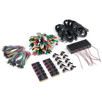 SparkFun Educator Lab Pack for micro:bit v2SPARKFUN
¥109,800税込¥120,780
1個
33日以内出荷
DescriptionThe micro:bit v2 Educator's Lab Pack includes 10 micro:bit v2 boards and everything you need to get you started with the new learning platform. The Lab Pack has everything you need, including micro:bits, cables, battery packs and a few parts to experiment with. This package provides an easy way to introduce your students to the micro:bit without any difficulty or parts hunting.SparkFun packages everything educators need to get started with the micro:bit in a variety of classroom settings and learning environments. The hardware boards, cables and extra parts come pre-packaged. Examples and curriculum materials are available from SparkFun and micro:bit, as well as from other educators involved in this growing maker education movement.Lab Packs are your classroom entry point. By combining our kits, popular boards and other educational tools with support materials(to be updated), SparkFun brings all the power of the open source community to the classroom. We've also updated the battery pack to be closer to what is in other micro:bit kits. It now requires 2xAAA batteries.The micro:bit is a pocket-sized computer that lets you get creative with digital technology. Between the micro:bit and our shield-like bit boards you can do almost anything while coding, customizing and controlling your micro:bit from almost anywhere! You can use your micro:bit for all sorts of unique creations, from robots to musical instruments and more. At half the size of a credit card, this versatile board has vast potential!FeaturesMicro:bit 2.0:64 MHz Arm Cortex-M4 with FPU512KB Flash128KB RAM5x5 Red LED ArrayTwo Programmable Buttons, one touch sensitive logoMEMS microphone and LED indicatorOnboard Light, Compass, Accelerometer, Temp Sensors and Speaker2.4 Ghz Micro:bit Radio/BLE 5.0 Smart Antenna25-pin Edge Connector4 dedicated GPIO, PWM, i2c, SPI, and ext. powerThree Digital/Analog Input/Output RingsTwo Power Rings --- 3V and GNDDedcated I2C bus for peripheralsMicroUSB Connector(5V)JST-PH Battery Connector(NotJST-XH)(3V)Power/reset Button with Status LED200 mA available for accessoriesProgram with C++, MakeCode, Python, Scratch
アズワン品番67-0424-92
 Mini Load Cell - 100g, Straight Bar TAL221SPARKFUN
¥5,198税込¥5,718
1個
欠品中
DescriptionThis miniature straight bar load cell(sometimes called a strain gauge)can translate up to 100g of pressure(force)into an electrical signal. Each load cell is able to measure the electrical resistance that changes in response to, and proportional of, the strain(e.g. pressure or force)applied to the bar. With this gauge you will be able to tell just how heavy an object is, if an object's weight changes over time, or if you simply need to sense the presence of an object by measuring strain or load applied to a surface.Each straight bar load cell is made from an aluminum-alloy and is capable of reading a capacity of 100g. These load cells have four strain gauges that are hooked up in a wheatstone bridge formation. The color code on the wiring is as follows:red = Exc+, green = Sig+, black = Exc-, and white = Sig-. Additionally, these load cells offer an IP65 protection rating and features four M3 sized through-holes for mounting purposes.Get Started with the Load Cell GuideFeaturesCapacity:100gMaterial:Aluminum-AlloyParallel Beam TypeIP65 Rating47mm×12mm×6mm, 110mm Wire
アズワン品番67-0426-82