カテゴリ
- 学童・教育用品(20)
- 測定用品(2)
絞り込み
ブランド
- SPARKFUN
- 三菱ふそう(97)
- ホンダ(85)
- BMW(33)
- TDKラムダ(26)
- コミネ(19)
- piaggio(ピアッジオグループ)(19)
- シュナイダーエレクトリック(18)
- RS PRO(12)
- トヨタ(10)
- ATEN(8)
- EVANS(8)
- KTM(8)
- carrozzeria(7)
- GPR Exhaust (ジーピーアールエキゾースト)(7)
- MAZDA(マツダ)(6)
- DUCATI(6)
- GATOR Case(4)
- スバル(3)
- ブランドをもっと見る
「rsev」の検索結果
 Diode Rectifier - 1A, 400V 1N4004SPARKFUN
¥89税込¥98
1個
33日以内出荷
DescriptionThis is a simple, subminiature size, axial lead mounted rectifier diode. Often used for reverse voltage protection, the 1N4004 is a staple for many power, DC to DC step up, and breadboard projects. The 1N4004 is rated for up to 1A/400V.
アズワン品番67-0421-18
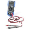
 Artech Digital Multimeter - A5020SPARKFUN
¥12,380税込¥13,618
1個
欠品中
DescriptionThe digital multimeter(DMM)is an essential tool in every electronic enthusiasts arsenal. This Smart Digital Multimeter, however, is not your average multimeter, it features a continuity sound at less than about 40±10Ω, current/voltage sense
アズワン品番67-0428-87
 Artech Digital Multimeter - A5030SPARKFUN
¥13,980税込¥15,378
1個
欠品中
DescriptionThe digital multimeter(DMM)is an essential tool in every electronic enthusiasts arsenal. This Smart Digital Multimeter, however, is not your average multimeter, it features a continuity sound at less than about 40±10Ω, current/voltage
アズワン品番67-0428-88
 Macchina A0 OBD-II Development ModuleSPARKFUN
¥30,980税込¥34,078
1個
33日以内出荷
DescriptionThe A0 in the latest in Macchina's line of OBD-II interfaces. The A0 uses the power of the ESP32 BLE and WiFi module to allow for wireless access to the OBD-II port most modern cars have.The Macchina A0 module plugs directly into the OBD-II port found in most modern cars and receives its power from the port. From there, one can interface with the device through a few different methods. The easiest is with software such as SavvyCAN, Torque Lite on Android. Besides getting all on board diagnostic information, you're able to control certain aspects of the car and create cool projects such as dash-mounted, shift lights. The A0 can also be programmed in the Arduino IDE, so there's plenty of possibilities to customize the device for what you want to do with your car!FeaturesODB-II compatibility with all modern cars(1996 or newer)Pre-loaded with SavvyCAN for plug and play(wireless!)reverse engineeringWiFi and Bluetooth(R)FunctionalityESP32 ProcessorSuper bright RGB LEDCAN Communication FunctionalityProgrammable with the Arduino IDE
アズワン品番67-0423-39
 SparkFun Breadboard Power Supply 5V/3.3VSPARKFUN
¥3,998税込¥4,398
1個
33日以内出荷
Here is a very simple breadboard power supply kit that takes power from a DC wall wart and outputs a selectable 5V or 3.3V regulated voltage. The .1" headers are mounted on the bottom of the PCB for simple insertion into a breadboard. Pins labeled VCC and GND plug directly into the power lines. The lone pair of pins have no electrical connection but help support the PCB.There are two pins available within the barrel jack footprint. Any stripped +/- DC supply can be connected instead of the barrel connector. Board has both an On/Off switch and a voltage select switch(3.3V/5V).Comes as a bag of parts kit and is easily assembled if you can follow the silkscreen indicators and have beginning experience with a soldering iron. You will need to read the resistor bands or use a multimeter to determine the resistor sizes.Dimensions:1.25x1.25"Kit Includes:DC Barrel Connector(2.1mm center positive)TO-220 Voltage Regulator(LM317 1.5A max current)1N4004 Reverse Protection Diode100uF 25V Capacitor10uF 25V Capacitor0.1uF 50V CapacitorRed Power LED - High Brightness2×SPDT Slide Switch4×0.1" Header Pins2×330 Resistor 1/6W390 Resistor 1/6W240 Resistor 1/6WBare PCB with Silkscreen IndicatorsPTC resettable fuse
仕様●項目1:組込み(組立てキット)●項目2:電源●項目4:リニア電源●項目8:ブレッドボード用電源アズワン品番67-0454-01
 SparkFun Qwiic HAT for Raspberry PiSPARKFUN
¥2,298税込¥2,528
1個
33日以内出荷
DescriptionThe SparkFun Qwiic HAT for Raspberry Pi is the quickest and easiest way to enter into SparkFun's Qwiic ecosystem while still using that Raspberry Pi that you've come to know and love. The Qwiic HAT connects the I2C bus(GND, 3.3V, SDA and SCL)on your Raspberry Pi to an array of Qwiic connectors on the HAT. Since the Qwiic system allows for daisy chaining boards with different addresses, you can stack as many sensors as you'd like to create a tower of sensing power!The Qwiic Pi HAT has four Qwiic connect ports, all on the same I2C bus. In addition, many of the useful GPIO pins on the Raspberry Pi are broken out. This HAT is compatible with any Raspberry Pi that utilizes the standard 2x20 GPIO header. It has been designed to sit to the side of the Pi, allowing it to work conveniently with a Pi Tin enclosure to connect boards to the Qwiic ports.Note:There is a small silk error that has reversed the SDA and SCL. This is simply a cosmetic mix-up and will not impact any function with this board.The SparkFun Qwiic Connect System is an ecosystem of I2C sensors, actuators, shields and cables that make prototyping faster and less prone to error. All Qwiic-enabled boards use a common 1mm pitch, 4-pin JST connector. This reduces the amount of required PCB space, and polarized connections mean you can't hook it up wrong.Get Started with the SparkFun Qwiic Pi HAT GuideFeatures4x Qwiic Connection PortsSelect GPIO Pins Broken OutPi Tin Compatibility
アズワン品番67-0422-50
 Audio Cable TRRS - 1ftSPARKFUN
¥749税込¥824
1個
欠品中
DescriptionThis is a foot-long white audio cable that has been terminated with two TRRS connectors at each end. TRRS connectors are the 3.5mm audio-style connectors that you see on some phones, MP3 players and development boards. TRRS stands for "Tip, Ring, Ring, Sleeve," which reflects the fact that, unlike a standard stereo connector, this actually has three conductors and a ground. Some devices use the extra conductor for a microphone(as in hands-free headsets)or to carry a video signal(as in some MP3/MP4 players). If you're hacking on something that has a 4-conductor audio jack, being able to plug straight in will keep your build clean and simple.We use and recommend this specific audio cable for our Spectacle product line.Features1ft long(30.5 cm)
アズワン品番67-0420-30
 Multimedia Wireless KeyboardSPARKFUN
¥9,998税込¥10,998
1個
33日以内出荷
DescriptionWith Single-Board Computers(SBCs)on the rise, it is a good idea to have an easy way to interface with them. Operating on a 2.4GHz frequency, the Multimedia Wireless Keyboard possesses a normal-sized key layout, media controls and a multitouch track pad. This keyboard is powered by a built-in 850mAh LiPo battery, providing you with 500--700 hours of use. Even if you don't have a Raspberry Pi, BeagleBone or another SBC, this keyboard can work with smart TVs, mobile devices and full-blown PCs!The Multimedia Wireless Keyboard can be charged via the attached USB cable, which stores in the same compartment as the wireless USB receiver. The track pad on the wireless keyboard not only features left and right click options, but also a scroll function. Measuring less than an inch thick, this wireless keyboard is an ideal product for on-the-go situations.Note:The attached USB cable is for charging purposes only.Features317.2mm×123.6mm×18.3mm(12.4in×4.8in×0.7in)System Requirements:HID-Compatible DeviceUSB PortWindows 2000, XP, CE, Vista, 7, 8 or HigherLinux(Debian-3.1, Red Hat-9.0, Ubuntu-8.10, Fedora-7.0)Android OS
アズワン品番67-0429-22
 TRRS Audio Plug - 3.5mm MetalSPARKFUN
¥579税込¥637
1個
欠品中
DescriptionTRRS connectors are the audio-style connectors that you see on some phones, MP3 players and development boards. TRRS stands for "Tip, Ring, Ring, Sleeve," which reflects the fact that, unlike a standard stereo connector, this actually has three conductors and a ground. Some devices use the extra conductor for a microphone(like hands-free headsets)or to carry a video signal(like in some MP3/MP4 players). If you're hacking on something that has a 4-conductor audio jack, being able to plug straight in will keep your build clean and simple.Note:This plug allows you to add a custom length of wire to your connector or repair a broken shroud on an existing cable you just cannot live without. Unfortunately, the supplier has not provided a datasheet or dimensional drawing please see the similar documents provided by other SparkFun products on the "documents" tab.
アズワン品番67-0421-42
 Weather Meter KitSPARKFUN
¥22,980税込¥25,278
1個
33日以内出荷
DescriptionWhether you're an agriculturalist, a professional meteorologist or a weather hobbyist, building your own weather station can be a really rewarding project. When you're measuring weather, however, you need some pretty specialized sensors. T
アズワン品番67-0427-13
 Teensy Stackable Header Kit ExtendedSPARKFUN
¥619税込¥681
1個
33日以内出荷
DescriptionThese headers are made to work with the Teensy 4.1, Teensy 3.6, and Teensy 3.5 development boards. Each set of headers allows for your Teensy to be easily incorporated into a breadboard circuit or attach a shield on top of the board. This kit includes three headers(two 24-pin, and one 5-pin), enough to connect your chosen Teensy in any configuration you need!
アズワン品番67-0425-96
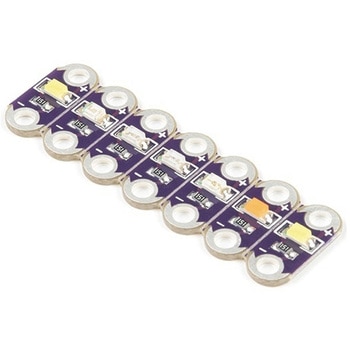 LilyPad Rainbow LED 6 ColorsSPARKFUN
¥1,398税込¥1,538
1個
33日以内出荷
DescriptionThis is the LilyPad Rainbow LED strip, with seven LilyPad LEDs that are still attached to one another, letting you snap LEDs apart at your leisure to sew into clothing or whatever else you can dream up.The LilyPad Rainbow LED features seven individual LEDs in six unique colors(Red, Blue, Green, Yellow, Pink, and White). Text has been added to the back of each board to indicate its color. Due to popular request, we have included two white LEDs instead of just one.Note:A portion of this sale is given back to Dr. Leah Buechley for continued development and education in e-textiles.
アズワン品番67-0422-27
 SparkFun OpenLog with HeadersSPARKFUN
¥6,898税込¥7,588
1個
欠品中
DescriptionThe SparkFun OpenLog with Headers is an open source data logger that works over a simple serial connection and supports microSD cards up to 64GB. The OpenLog can store or "log" huge amounts of serial data and act as a black box of sorts to store all the serial data that your project generates, for scientific or debugging purposes. This version of th OpenLog even includes pre-soldered headers for your convenience.The SparkFun OpenLog uses an ATmega328 running at 16MHz thanks to the onboard resonator. The OpenLog draws approximately 2-3mA in idle(nothing to record)mode. During a full record OpenLog can draw 10 to 20mA depending on the microSD card being used.All data logged by the OpenLog is stored on the microSD card. Any 512MB to 32GB microSD card should work. OpenLog supports both FAT16 and FAT32 SD formats.For even better performance the OpenLog Artemis is the tool you need, featuring logging speeds up to 500000bps.Get Started with the SparkFun OpenLog GuideFeaturesVCC Input:3.3V-12V(Recommended 3.3V-5V)Log to low-cost microSD FAT16/32 cards up to 32GBSimple command interfaceConfigurable baud rates(up to 115200bps)Preprogrammed ATmega328 and bootloaderFour SPI pogo pinsTwo LEDs indicate writing status2mA idle, 6mA at maximum recording ratePre-soldered Headers
アズワン品番67-0422-30
 SparkFun MicroMod Qwiic Carrier Board - DoubleSPARKFUN
¥4,298税込¥4,728
1個
33日以内出荷
DescriptionThe MicroMod Qwiic Carrier Board can be used to rapidly prototype with other Qwiic devices. The MicroMod M.2 socket provides users the freedom to experiment with any processor board in the MicroMod ecosystem. This board also features two Qwiic connectors and eight 4-40 screw inserts to connect and mount Qwiic devices.This version of the SparkFun MicroMod Qwiic Carrier Board features two ports for our standard 1in. by 1in. Qwiic breakouts. However, you aren't beholden to attaching just a duo of Qwiic breakouts since you are able to stack the boards on top of each other, allowing you to hook up a full circuit of Qwiic sensors and accessories to fully utilize your next project!MicroMod is a modular interface ecosystem that connects a microcontroller "processor board" to various "carrier board" peripherals. Utilizing the M.2 standard, the MicroMod standard is designed to easily swap out processors on the fly. Pair a specialized carrier board for the project you need with your choice of compatible processor!Get Started With the MicroMod Qwiic Carrier Board GuideFeaturesM.2 MicroMod(Processor Board)ConnectorUSB-C Connector3.3V 1A Voltage RegulatorQwiic ConnectorsBoot/Reset ButtonsCharge CircuitEight 4-40 Inserts
アズワン品番67-0423-51
 SparkFun MicroMod Qwiic Carrier Board - SingleSPARKFUN
¥3,500税込¥3,850
1個
33日以内出荷
DescriptionThe MicroMod Qwiic Carrier Board can be used to rapidly prototype with other Qwiic devices. The MicroMod M.2 socket provides users the freedom to experiment with any processor board in the MicroMod ecosystem. This board also features two Qwiic connectors and four 4-40 screw inserts to connect and mount Qwiic devices.This version of the SparkFun MicroMod Qwiic Carrier Board features a single port for our standard 1in. by 1in. Qwiic Breakouts. However, you aren't beholden to attaching just one Qwiic breakout since you are able to stack the boards on top of each other, allowing you to hook up a full circuit of Qwiic sensors and accessories to fully utilize your next project!MicroMod is a modular interface ecosystem that connects a microcontroller "processor board" to various "carrier board" peripherals. Utilizing the M.2 standard, the MicroMod standard is designed to easily swap out processors on the fly. Pair a specialized carrier board for the project you need with your choice of compatible processor!Get Started With the MicroMod Qwiic Carrier Board GuideFeaturesM.2 MicroMod(Processor Board)ConnectorUSB-C Connector3.3V 1A Voltage RegulatorQwiic ConnectorsBoot/Reset ButtonsCharge CircuitFour 4-40 Inserts
アズワン品番67-0423-50
 SparkFun Inventor's Kit for Arduino Uno - v4.1SPARKFUN
¥34,980税込¥38,478
1個
33日以内出荷
DescriptionThe SparkFun Inventor's Kit(SIK)for Arduino Uno is a great way to get started with programming and hardware interaction with the Arduino programming language. The SIK includes everything you need to complete five overarching projects consisting of 16 interconnected circuits that teach everything from blinking an LED to reading sensors. The culminating project is your very own autonomous robot! No previous programming or electronics experience is required to use this kit.The online guide contains step-by-step instructions with circuit diagrams and hookup tables for building each project and circuit with the included parts. Full example code is provided, new concepts and components are explained at point of use, and troubleshooting tips offer assistance if something goes wrong.The kit does not require any soldering and is recommended for beginners ages 10 and up who are looking for an Arduino starter kit. For SIK version 4.1 we took an entirely different approach to teaching embedded electronics. In previous versions of the SIK, each circuit focused on introducing a new piece of technology. With SIK v4.1, components are introduced in the context of the circuit you are building, and each circuit builds upon the last, leading up to a project that incorporates all of the components and concepts introduced throughout the guide. With new parts and a completely new strategy, even if you've used the SIK before, you're in for a brand-new experience!This version of the SIK replaces the SparkFun RedBoard Qwiic with the Arduino Uno(SMD version)and comes without the SIK guidebook and carrying case. With these components being swapped and removed, we were able to reduce the overall size and weight of the kit, making shipping cheaper and easier for anyone ordering internationally.Note:As stated above, this SIK does NOT include a carrying case or print guidebook.Get Started With the SparkFun Inventor's Kit v4.1 Experiment GuideExamplesProject 1:LightCircuit 1A:Blinking an LEDCircuit 1B:PotentiometerCircuit 1C:PhotoresistorCircuit 1D:RGB Night-LightProject 2:SoundCircuit 2A:BuzzerCircuit 2B:Digital TrumpetCircuit 2C:"Simon Says" GameProject 3:MotionCircuit 3A:Servo MotorsCircuit 3B:Distance SensorCircuit 3C:Motion AlarmProject 4:DisplayCircuit 4A:LCD "Hello, World!"Circuit 4B:Temperature SensorCircuit 4C:"DIY Who Am I?" GameProject 5:RobotCircuit 5A:Motor BasicsCircuit 5B:Remote-Controlled RobotCircuit 5C:Autonomous Robot
アズワン品番67-0424-34
 SparkFun 2D Barcode Scanner BreakoutSPARKFUN
¥20,980税込¥23,078
1個
欠品中
DescriptionThe SparkFun 2D Barcode Scanner Breakout is a nifty little breakout board featuring the DE2120 barcode scanner module from DYScan. The DE2120 reads 20 different barcode symbologies(both 1D and 2D)using a camera coupled with on-board image processing to identify and decode everything from UPC codes to QR codes. The module also features two LEDs:one for illumination and one to project the red line that you're used to seeing from laser-based scanners.This breakout board makes it easy to explore all of the capabilities of the DE2120 without dealing with finicky flat flex cables. The scanner's USB interface is exposed via the on-board USB-C connector. A buzzer and status LED are connected to the module through appropriate drive circuits and a push button tactile switch is provided on the "trigger" pin. When you're ready to incorporate the module into your embedded project, you can leverage the 5 pin header for direct access to the TTL serial pins, power pins, and trigger input.The module can be configured either by using the serial interface or by scanning command barcodes found in the Settings Manual.All keyboard, HID, and serial can be transmitted over the single USB-C connector. The DE2120 has the unique ability to enumerate all three protocols including a CDC serial driver so the device appears as a standard COM port.Get Started with the 2D Barcode Scanner Breakout Hookup GuideFeaturesUSB-C Connector for USB HID Interface and Virtual COM portReads 20 different symbologies1D SymbologiesUPC-AUPC-EEAN-8EAN-13Code 128GS1-128Code 39Code 93Code 11Interleaved 2-of-5Matrix 2-of-5Industrial 2-of-5CodabarMSIGS1 DataBarDatalogic 2-of-52D SymbologiesQR CodeData MatrixPDF 417Micro PDF 417Aztec Code
アズワン品番67-0430-36
 SparkFun Qwiic Motor DriverSPARKFUN
¥6,698税込¥7,368
1個
欠品中
DescriptionThe SparkFun Qwiic Motor Driver takes all the great features of the Serial Controlled Motor Driver(SCMD)and miniaturizes them, adding Qwiic ports for plug and play functionality. Boasting the same 4245 PSOC and 2-channel motor ports as the SCMD, the SparkFun Qwiic Motor Driver is designed to communicate over I2C to make setting up your next robotic project as fast and easy as possible! Utilizing our handy Qwiic system and screw terminals for motor and power hook-up, no soldering is required to connect it to the rest of your system.With 1.2A steady state drive per channel(1.5A peak)and 127 levels of DC drive strength, this little Qwiic board is perfect for your small DC motor driver needs. Since the Qwiic Motor Driver is a 3.3V logic device, you'll need to use a logic level converter to interface to 5V.The I2C address of the Qwiic Motor Driver is 0x5D and is jumper selectable to 0x58, 0x59, 0x5A, 0x5B, ... 0x63.The SparkFun Qwiic Connect System is an ecosystem of I2C sensors, actuators, shields and cables that make prototyping faster and less prone to error. All Qwiic-enabled boards use a common 1mm pitch, 4-pin JST connector. This reduces the amount of required PCB space, and polarized connections mean you can't hook it up wrong.Need a custom board? This component can be found in SparkFun's A La Carte board builder. You can have a custom design fabricated with this component - and your choice of hundreds of other sensors, actuators and wireless devices - delivered to you in just a few weeks.Get Started With the Qwiic Motor Driver Hookup GuideFeatures1.5 A peak drive per channel, 1.2 A steady stateOperates from 3 to 11 Volts with 12V absolute max3.3V default VCC and logic127 levels of DC drive strength.Controllable by I2C or TTL UART signalsDirection inversion on a per motor basisGlobal Drive enableExposed small heat sink shapeSeveral I2C addresses, default UART bauds availableAdjustable I2C Address:0x5D Default2x Qwiic ConnectorsDocumentsSchematicEagle FilesBoard DimensionsHookup GuideArduino LibraryPython ModuleGithub Hardware Repo
アズワン品番67-0426-33
 SparkFun Inventor's Kit Bridge Pack for micro:bitSPARKFUN
¥15,980税込¥17,578
1個
33日以内出荷
DescriptionDo you own micro:bit or micro:bit Go Bundle and want to expand your skills with the new microcontroller? You are in luck! The SparkFun Inventor's Kit Bridge Pack for micro:bit was designed to provide you with an easy way to transform your m:b into full fledged learning kit! Each Bridge Pack includes all of the parts found in the SIK for micro:bit that aren't included with the Go Bundle. With the SIK Bridge Pack for micro:bit you will be able to complete circuits that will teach you how to read sensors, move motors, build Bluetooth(R)devices and more.The micro:bit is pocket-sized computer that lets you get creative with digital technology. Between the micro:bit and our shield-like bit boards you can do almost anything while coding, customizing and controlling your micro:bit from almost anywhere! You can use your micro:bit for all sorts of unique creations, from robots to musical instruments and more. At half the size of credit card, this versatile board has vast potential!Note:The Bridge Pack is NOT full SparkFun Inventor's Kit and only includes the parts to complement micro:bit Go Bundle or standalone board. That also means that this kit doesnotinclude micro:bit, which will need to be purchased separately.Get started with the micro:bit SIK Experiment GuideExamplesCircuit 0:Hello, micro:bit!Circuit 1:Blinking an LEDCircuit 2:Reading PotentiometerCircuit 3:Reading PhotoresistorCircuit 4:Driving an RGB LEDCircuit 5:Reading an SPDT SwitchCircuit 6:Reading Button PressCircuit 7:Reading the Temperature SensorCircuit 8:Using Servo MotorCircuit 9:Using BuzzerCircuit 10:Using the AccelerometerCircuit 11:Using the Compass
アズワン品番67-0424-21
 SparkFun Inventor's Kit for micro:bit v2SPARKFUN
¥17,980税込¥19,778
1個
33日以内出荷
DescriptionThe SparkFun Inventor's Kit(SIK)for micro:bit v2 is a great way to get creative, connected and coding with the micro:bit. The SIK for micro:bit v2 provides not only the micro:bit v2 board but everything you need to hook up and experiment with multiple electronic circuits! With the SIK for micro:bit v2 you will be able to complete circuits that will teach you how to read sensors, move motors, build Bluetooth(R)devices and more.The SparkFun Inventor's Kit for micro:bit is the latest and greatest in single-board computer kits. Surrounding the micro:bit v2 SIK is one core philosophy --- that anyone can(and should)experiment with cutting-edge electronics in a fun and playful way without breaking the bank.The kit does not require any soldering and is recommended for all users, from beginners to engineers. We have provided a complete Experiment Guide in the Documents tab for you to check out now! If you have ever been interested in learning about electronics, or if you have used the original SparkFun Inventor's Kit and are looking for something new, the SIK for micro:bit is the perfect kit for you!The micro:bit is a pocket-sized computer that lets you get creative with digital technology. Between the micro:bit and our shield-like bit boards you can do almost anything while coding, customizing and controlling your micro:bit from almost anywhere! You can use your micro:bit for all sorts of unique creations, from robots to musical instruments and more. At half the size of a credit card, this versatile board has vast potential!ExamplesCircuit 0:Hello, micro:bit!Circuit 1:Blinking an LEDCircuit 2:Reading a PotentiometerCircuit 3:Reading a PhotoresistorCircuit 4:Driving an RGB LEDCircuit 5:Reading an SPDT SwitchCircuit 6:Reading a Button PressCircuit 7:Reading the Temperature SensorCircuit 8:Using a Servo MotorCircuit 9:Using a BuzzerCircuit 10:Using the AccelerometerCircuit 11:Using the Compass
アズワン品番67-0424-61
 SparkFun 9DoF IMU Breakout - ICM-20948 QwiicSPARKFUN
¥7,298税込¥8,028
1個
欠品中
DescriptionThe SparkFun 9DoF IMU Breakout incorporates all the amazing features of Invensense's ICM-20948 into a Qwiic-enabled breakout board complete with a logic shifter and broken out GPIO pins for all your motion sensing needs. The ICM-20948 itself is an extremely low powered, I2C and SPI enabled 9-axis motion tracking device that is ideally suited for smartphones, tablets, wearable sensors, and IoT applications. Utilizing our handy Qwiic system, no soldering is required to connect it to the rest of your system. However, we still have broken out 0.1"-spaced pins in case you prefer to use a breadboard.In addition to the 3-Axis Gyroscope with four selectable ranges, 3-Axis Accelerometer, again with four selectable ranges, and 3-axis magnetometer with an FSR to ±4900μT, the ICM-20948 also includes a Digital Motion Processor that offloads the computation of motion sensing algorithms from the detectors, allowing optimal performance of the sensors. We've also broken out all the ICM-20948 pin functionality to GPIO and labeled them I2C on the front, SPI on the back for ease of identification.Note:The I2C address of the ICM-20948 is 0x69 and is jumper selectable to 0x68. A multiplexer/Mux is required to communicate to multiple ICM-20948 sensors on a single bus. If you need to use more than one ICM-20948 sensor consider using the Qwiic Mux Breakout.The SparkFun Qwiic Connect System is an ecosystem of I2C sensors, actuators, shields and cables that make prototyping faster and less prone to error. All Qwiic-enabled boards use a common 1mm pitch, 4-pin JST connector. This reduces the amount of required PCB space, and polarized connections mean you can't hook it up wrong.Need a custom board? This component can be found in SparkFun's A La Carte board builder. You can have a custom design fabricated with this component - and your choice of hundreds of other sensors, actuators and wireless devices - delivered to you in just a few weeks.Get Started with the SparkFun ICM-20948 9DoF IMU GuideFeatures1.95 V to 3.6 V supply voltageTriple-axis MEMS gyroscope with user-programmable full-scale range of ±250 dps, ±500 dps, ±1000 dps, and ±2000 dpsTriple-axis MEMS accelerometer with programmable full scale range of ±2g, ±4g, ±8g, and ±16gTriple-axis silicon monolithic Hall-effect magnetic sensor with full scale measurement range to ±4900 μTI2C at up to 100 kHz(standard-mode)or up to 400 kHz(fast-mode)or SPI at up to 7 MHz for communicationwith registersOn-board digital motion processor(DMP)Digital-output temperature sensor2x Qwiic Connection PortsI2C Address:0x69(0x68 with Jumper)DocumentsSchematicEagle FilesHookup GuideDatasheet(ICM-20948)Arduino LibraryPython Support(Qwiic_Py)GitHub Hardware Repo
アズワン品番67-0427-05
 SparkFun High Precision Temperature Sensor - TMP117 QwiicSPARKFUN
¥4,898税込¥5,388
1個
33日以内出荷
DescriptionThe SparkFun Qwiic TMP117 breakout is a high precision temperature sensor equipped with an I2C interface. It outputs temperature readings with high precision of ±0.1℃ across the temperature range of -20℃ to +50℃s with no calibration and a maximum range from -55℃ to 150℃. The SparkFun High Precision Temperature Sensor also has a very low power consumption rate which minimizes the impact of self-heating on measurement accuracy. Utilizing our handy Qwiic system, no soldering is required to connect it to the rest of your system. However, we still have broken out 0.1"-spaced pins in case you prefer to use a breadboard.The SparkFun High Precision Temperature Sensor also includes programmable temperature limits, and digital offset for system correction. While the TMP102 is capable of reading temperatures to a resolution of 0.0625℃ and is accurate up to 0.5℃, the on-board TMP117 is not only more precise but has a 16-bit resolution of 0.0078℃!To make this breakout even easier to use, we've written an Arduino library to help you get started "Qwiic-ly." Check the Documents tab above for more information.The SparkFun Qwiic Connect System is an ecosystem of I2C sensors, actuators, shields and cables that make prototyping faster and less prone to error. All Qwiic-enabled boards use a common 1mm pitch, 4-pin JST connector. This reduces the amount of required PCB space, and polarized connections mean you can't hook it up wrong.The TMP117 High Precision Temperature Sensor can also be automatically detected, scanned, configured, and logged using the OpenLog Artemis datalogger system. No programming, soldering, or setup required!Need a custom board? This component can be found in SparkFun's A La Carte board builder. You can have a custom design fabricated with this component - and your choice of hundreds of other sensors, actuators and wireless devices - delivered to you in just a few weeks.Get Started with the SparkFun High Precision TMP117 Hookup GuideFeaturesUses I2C interface(Qwiic-enabled)Four selectable addresses0x48(default), 0x49, 0x4A, 0x4B16-bit resolution, 0.0078℃High accuracy, digital temperature sensor±0.1℃(max)from ?20℃ to 50℃±0.15℃(max)from ?40℃ to 70℃±0.2℃(max)from ?40℃ to 100℃±0.25℃(max)from ?55℃ to 125℃±0.3℃(max)from ?55℃ to 150℃Operating temperature range-55℃ to +150℃Operating voltage range1.8V to 5.5VTypically 3.3V if using the Qwiic cableLow power consumption3.5μA(1-Hz conversion cycle)150nA(shutdown current)Programmable operating modesContinuous, one-shot, and shutdownProgrammable temperature alert limitsSelectable averaging for reduced noiseDigital offset for system correctionNIST traceabilityDocumentsSchematicEagle FilesBoard DimensionsHookup GuideDatasheet(TMP117)Arduino LibraryGitHub Hardware Repo
アズワン品番67-0427-10