カテゴリ
- 学童・教育用品(30)
絞り込み
ブランド
- SPARKFUN
- Scorpion (スコーピオン)(155)
- IAI(アイエイアイ)(10)
- フエニックス・コンタクト(4)
- シュナイダーエレクトリック(4)
- SMC(3)
- RS PRO(3)
- イノック(1)
- SKF(日本エスケイエフ)(1)
- オリエンタルモーター(1)
- コーセル(1)
- 水本機械製作所(1)
- ワゴジャパン(1)
- DAYTONA(デイトナ)(1)
- GIVI(ジビ)(1)
- HYPERPRO(ハイパープロ)(1)
- 神津精機(1)
- AMPHENOL(1)
- TRACO POWER(1)
- ブランドをもっと見る
「scon cb」の検索結果
 Thermocouple Connector - PCC-SMP-KSPARKFUN
¥3,798税込¥4,178
1個
9日以内出荷
DescriptionThis Thermocouple Connector is perfect for bridging the gap between Type-K thermocouples with standard connectors with a PCB. This little connector is actually the exact part we recommend using with our SparkFun Thermocouple Breakout! Each
アズワン品番67-0425-14
 Flexible Qwiic Cable - 50mmSPARKFUN
¥469税込¥516
1個
33日以内出荷
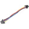
DescriptionThis is a 50mm long 4-conductor cable with 1mm JST termination. It's designed to connect Qwiic enabled components together but can be used for other applications as well. The cable insulation is made from a highly malleable material making it more flexible than our original Qwiic cable particularly in tight spaces or enclosures.Each Qwiic Cable's wires have been color coded to red, black, blue and yellow.The SparkFun Qwiic connect system is an ecosystem of I2C sensors, actuators, shields and cables that make prototyping faster and less prone to error. All Qwiic-enabled boards use a common 1mm pitch, 4-pin JST connector. This reduces the amount of required PCB space, and polarized connections mean you can't hook it up wrong.FeaturesDimensions:50mm(1.96")Length
アズワン品番67-0426-06
 Qwiic Cable - Grove Adapter 100mmSPARKFUN
¥709税込¥780
1個
33日以内出荷
DescriptionWith the SparkFun Qwiic Connect System expanding every day, we want to make sure it becomes as accessible as possible but we understand there are other systems that can compliment it out there. The Qwiic to Grove Adapter Cable allows interoperability between the SparkFun Qwiic Connect System and the I2C based Grove boards from Seeed Studio. Now you can plug Seeed Studio boards you may have onto the Qwiic bus or you can use this cable to introduce Qwiic sensors, inputs, and outputs into your Grove system.Note:The Grove system has a variety of different signal systems that use the same connector. This cableonlyworks with the I2C variety.The SparkFun Qwiic connect system is an ecosystem of I2C sensors, actuators, shields and cables that make prototyping faster and less prone to error. All Qwiic-enabled boards use a common 1mm pitch, 4-pin JST connector. This reduces the amount of required PCB space, and polarized connections mean you can't hook it up wrong.FeaturesLength:100mm
アズワン品番67-0425-61
 SparkFun GPS Breakout - NEO-M9N, SMA QwiicSPARKFUN
¥22,980税込¥25,278
1個
33日以内出荷
DescriptionThe SparkFun NEO-M9N GPS Breakout is a high quality GPS board with equally impressive configuration options including SMA. The NEO-M9N module is a 92-channel u-blox M9 engine GNSS receiver, meaning it can receive signals from the GPS, GLONASS, Galileo, and BeiDou constellations with ~1.5 meter accuracy. This breakout supports concurrent reception of four GNSS. This maximizes position accuracy in challenging conditions increasing, precision and decreases lock time; and thanks to the onboard rechargeable battery, you'll have backup power enabling the GPS to get a hot lock within seconds! Additionally, this u-blox receiver supports I2C(u-blox calls this Display Data Channel)which makes it perfect for the Qwiic compatibility so we don't have to use up our precious UART ports. Utilizing our handy Qwiic system, no soldering is required to connect it to the rest of your system. However, we still have broken out 0.1"-spaced pins in case you prefer to use a breadboard.The NEO-M9N module detects jamming and spoofing events and can report them to the host, so that the system can react to such events. A SAW(Surface Acoustic Wave)filter combined with an LNA(Low Noise Amplifier)in the RF path is integrated into the NEO-M9N module which allows normal operation even under strong RF interferences.U-blox based GPS products are configurable using the popular, but dense, windows program called u-center. Plenty of different functions can be configured on the NEO-M9N:baud rates, update rates, geofencing, spoofing detection, external interrupts, SBAS/D-GPS, etc. All of this can be done within the SparkFun Arduino Library!The SparkFun NEO-M9N GPS Breakout is also equipped with an on-board rechargeable battery that provides power to the RTC on the NEO-M9N. This reduces the time-to-first fix from a cold start(~24s)to a hot start(~2s). The battery will maintain RTC and GNSS orbit data without being connected to power for plenty of time.This product requires an antenna:Be sure to check out the related products/hookup accessories and pick a suitable SMA antenna for your project.The SparkFun Qwiic Connect System is an ecosystem of I2C sensors, actuators, shields and cables that make prototyping faster and less prone to error. All Qwiic-enabled boards use a common 1mm pitch, 4-pin JST connector. This reduces the amount of required PCB space, and polarized connections mean you can't hook it up wrong.The NEO-M9N GPS Breakout can also be automatically detected, scanned, configured, and logged using the OpenLog Artemis datalogger system. No programming, soldering, or setup required!Get Started With the SparkFun NEO-M9N GPS GuideFeaturesIntegrated SMA connector for use with antenna of your choice92-Channel GNSS Receiver1.5m Horizontal Accuracy25Hz Max Update Rate(four concurrent GNSS)Time-To-First-Fix:Cold:24sHot:2sMax Altitude:80,000mMax G:≦4Max Velocity:500m/sVelocity Accuracy:0.05m/sHeading Accuracy:0.3 degreesTime Pulse Accuracy:30ns3.3V VCC and I/OCurrent Consumption:~31mA Tracking GPS+GLONASSSoftware ConfigurableGeofencingOdometerSpoofing DetectionExternal InterruptPin ControlLow Power ModeMany others!Supports NMEA, UBX, and RTCM protocols over UART or I2C interfaces
アズワン品番67-0423-87
 SparkFun Snappable ProtoboardSPARKFUN
¥4,298税込¥4,728
1個
欠品中
DescriptionSometimes it's nice to have a protoboard that's super long and skinny, super small, or just a bunch of holes. The SparkFun Snappable Protoboard is a large PCB crisscrossed with v-scored lines so that you can choose just how long and wide yo
アズワン品番67-0425-13
 DC Barrel Power Jack/Connector SMDSPARKFUN
¥699税込¥769
1個
欠品中
DescriptionThis is a common SMD barrel-type power jack for DC wall supplies. These are compatible with our DC wall supplies and have a 5.5mm jack, with a 2.1mm center pole diameter.
アズワン品番67-0425-10
 SparkFun Beefcake Relay Control Kit Ver. 2.0SPARKFUN
¥3,198税込¥3,518
1個
33日以内出荷
DescriptionYour 5V system can wield great power with this big, beefy relay board. How does 10A on the NC contacts and 20A on the NO contacts at 220VAC sound? The SparkFun Beefcake Relay Control Kit contains all the parts you need to get your high-power load under control. Only minimal assembly is required!The heart of the board is sealed, SPDT 20A/10A Relay. The relay is controlled by 5V logic through transistor, and an LED tells you when the relay is closed. This is kit, so it comes as through-hole parts with assembly required, which makes for some nice soldering practice. Screw terminal connectors on either side of the board make it easy to incorporate into your project.There are some pretty beefy traces connecting the relay to the load pins, but the 3-pin terminals are only rated for 15A max! If you plan on connecting larger load, you'll need to solder directly to the board. As always with high current and voltage, play it safe and use your judgment when deciding how much of load you want to put on board -- in open airflow the PCB can handle the full 20A for few minutes at time, but in an enclosed area heat can build up.Note:Please keep in mind that this board is really meant for someone with experience and good knowledge of electricity. If you're uncomfortable soldering or dealing with high voltage, please check out the IoT Power Relay. The IoT Power Relay is fully enclosed, making it lot safer.Get Started With the Beefcake Hookup Assembly GuideFeaturesVoltage Rating:220VAC/28VDCVCC requirements:4-6V, 150mA capableSPDT pins exposed(Form C)14 AWG screw terminals for relay connections.10 AWG solder lugs for relay connections.Flyback diode includedZener recovery diode included(decreases turn-off time)Heavy oz. copper on PCB
アズワン品番67-0424-03
 Flexible Qwiic Cable - 200mmSPARKFUN
¥679税込¥747
1個
33日以内出荷
DescriptionThis is a 200mm long 4-conductor cable with 1mm JST termination. It's designed to connect Qwiic enabled components together but can be used for other applications as well. The cable insulation is made from a highly malleable material making it more flexible than our original Qwiic cable particularly in tight spaces or enclosures.Each Qwiic Cable's wires have been color coded to red, black, blue and yellow.The SparkFun Qwiic connect system is an ecosystem of I2C sensors, actuators, shields and cables that make prototyping faster and less prone to error. All Qwiic-enabled boards use a common 1mm pitch, 4-pin JST connector. This reduces the amount of required PCB space, and polarized connections mean you can't hook it up wrong.FeaturesDimensions:200mm(7.87")Length
アズワン品番67-0426-04
 Flexible Qwiic Cable - 100mmSPARKFUN
¥659税込¥725
1個
33日以内出荷
DescriptionThis is a 100mm long 4-conductor cable with 1mm JST termination. It's designed to connect Qwiic enabled components together but can be used for other applications as well. The cable insulation is made from a highly malleable material making it more flexible than our original Qwiic cable particularly in tight spaces or enclosures.Each Qwiic Cable's wires have been color coded to red, black, blue and yellow.The SparkFun Qwiic connect system is an ecosystem of I2C sensors, actuators, shields and cables that make prototyping faster and less prone to error. All Qwiic-enabled boards use a common 1mm pitch, 4-pin JST connector. This reduces the amount of required PCB space, and polarized connections mean you can't hook it up wrong.FeaturesDimensions:100mm(3.93")Length
アズワン品番67-0426-05
 SparkFun Qwiic Cable KitSPARKFUN
¥3,898税込¥4,288
1個
欠品中
DescriptionThe SparkFun Qwiic Connect System is constantly growing in popularity with makers. So to make it even easier to get started, we've assembled this Qwiic Cable Kit for everyone. If you aren't sure which Qwiic cable to use, this handy box includes all of them allowing you to save a little money and time! It has a little something for everyone.The SparkFun Qwiic Cable Kit includes 10 cables of various lengths and styles that will get your Qwiic boards connected together, to a development platform, or to a breadboard. Each Qwiic Cable's wires have been color coded to red, black, blue and yellow with 1mm JST termination.The SparkFun Qwiic connect system is an ecosystem of I2C sensors, actuators, shields and cables that make prototyping faster and less prone to error. All Qwiic-enabled boards use a common 1mm pitch, 4-pin JST connector. This reduces the amount of required PCB space, and polarized connections mean you can't hook it up wrong.
アズワン品番67-0424-24
 SparkFun Qwiic AdapterSPARKFUN
¥479税込¥527
1個
33日以内出荷
DescriptionThe SparkFun Qwiic Adapter provides the perfect means to make any old I2C board into a Qwiic-enabled board. This adapter breaks out the I2C pins from the Qwiic connectors to pins that you can easily solder with your favorite I2C-enabled device.The Qwiic Adapter has two Qwiic connection ports, all on the same I2C bus. Four plated through holes are broken out for SCL, SDA, 3.3V and GND. These pins can be used to convert an old I2C-enabled device into a Qwiic-enabled board.The SparkFun Qwiic Connect System is an ecosystem of I2C sensors, actuators, shields and cables that make prototyping faster and less prone to error. All Qwiic-enabled boards use a common 1mm pitch, 4-pin JST connector. This reduces the amount of required PCB space, and polarized connections mean you can't hook it up wrong.Get Started with the SparkFun Qwiic Adapter GuideFeatures2x Qwiic Connection PortsBroken-out I2C Pins
アズワン品番67-0419-69
 SparkFun Qwiic Alphanumeric Display - COMシリーズSPARKFUN
¥2,998税込¥3,298
1個
33日以内出荷
DescriptionThe SparkFun Alphanumeric Display Arduino library makes printing strings to the display as easy as calling the print()function. With this library, you'll be able to send I2C commands to the VK16K33 LED driver chip to light up segments(including the decimal point or colon)and even scroll your string across the display. You can download the library through the Arduino library manager by searching 'SparkFun Alphanumeric Display' or you can get the GitHub repo as a .zip file and install the library from there.The SparkFun Qwiic Connect System is an ecosystem of I2C sensors, actuators, shields and cables that make prototyping faster and less prone to error. All Qwiic-enabled boards use a common 1mm pitch, 4-pin JST connector. This reduces the amount of required PCB space, and polarized connections mean you can't hook it up wrong.Get Started with the Qwiic Alphanumeric Display Hookup GuideFeaturesOperating Voltage:3.3VIntegrated RC oscillatorMaximum display segment numbers:128 patterns13×3 matrix key scan circuit16-step dimming circuitI2C Addresses:0x70(0x71, 0x72, 0x73)2x Qwiic connectors2x Wall Mounting Points
アズワン品番67-0421-61
 SparkFun Qwiic Alphanumeric Display - COMシリーズSPARKFUN
¥2,998税込¥3,298
1個
33日以内出荷
DescriptionThe SparkFun Alphanumeric Display Arduino library makes printing strings to the display as easy as calling the print()function. With this library, you'll be able to send I2C commands to the VK16K33 LED driver chip to light up segments(including the decimal point or colon)and even scroll your string across the display. You can download the library through the Arduino library manager by searching 'SparkFun Alphanumeric Display' or you can get the GitHub repo as a .zip file and install the library from there.The SparkFun Qwiic Connect System is an ecosystem of I2C sensors, actuators, shields and cables that make prototyping faster and less prone to error. All Qwiic-enabled boards use a common 1mm pitch, 4-pin JST connector. This reduces the amount of required PCB space, and polarized connections mean you can't hook it up wrong.Get Started with the Qwiic Alphanumeric Display Hookup GuideFeaturesOperating Voltage:3.3VIntegrated RC oscillatorMaximum display segment numbers:128 patterns13×3 matrix key scan circuit16-step dimming circuitI2C Addresses:0x70(0x71, 0x72, 0x73)2x Qwiic connectors2x Wall Mounting Points
アズワン品番67-0421-62
 SparkFun Qwiic Alphanumeric Display - COMシリーズSPARKFUN
¥3,198税込¥3,518
1個
33日以内出荷
DescriptionThe SparkFun Alphanumeric Display Arduino library makes printing strings to the display as easy as calling the print()function. With this library, you'll be able to send I2C commands to the VK16K33 LED driver chip to light up segments(including the decimal point or colon)and even scroll your string across the display. You can download the library through the Arduino library manager by searching 'SparkFun Alphanumeric Display' or you can get the GitHub repo as a .zip file and install the library from there.The SparkFun Qwiic Connect System is an ecosystem of I2C sensors, actuators, shields and cables that make prototyping faster and less prone to error. All Qwiic-enabled boards use a common 1mm pitch, 4-pin JST connector. This reduces the amount of required PCB space, and polarized connections mean you can't hook it up wrong.Get Started with the Qwiic Alphanumeric Display Hookup GuideFeaturesOperating Voltage:3.3VIntegrated RC oscillatorMaximum display segment numbers:128 patterns13×3 matrix key scan circuit16-step dimming circuitI2C Addresses:0x70(0x71, 0x72, 0x73)2x Qwiic connectors2x Wall Mounting Points
アズワン品番67-0421-64
 SparkFun Qwiic Alphanumeric Display - COMシリーズSPARKFUN
¥2,998税込¥3,298
1個
33日以内出荷
DescriptionThe SparkFun Alphanumeric Display Arduino library makes printing strings to the display as easy as calling the print()function. With this library, you'll be able to send I2C commands to the VK16K33 LED driver chip to light up segments(including the decimal point or colon)and even scroll your string across the display. You can download the library through the Arduino library manager by searching 'SparkFun Alphanumeric Display' or you can get the GitHub repo as a .zip file and install the library from there.The SparkFun Qwiic Connect System is an ecosystem of I2C sensors, actuators, shields and cables that make prototyping faster and less prone to error. All Qwiic-enabled boards use a common 1mm pitch, 4-pin JST connector. This reduces the amount of required PCB space, and polarized connections mean you can't hook it up wrong.Get Started with the Qwiic Alphanumeric Display Hookup GuideFeaturesOperating Voltage:3.3VIntegrated RC oscillatorMaximum display segment numbers:128 patterns13×3 matrix key scan circuit16-step dimming circuitI2C Addresses:0x70(0x71, 0x72, 0x73)2x Qwiic connectors2x Wall Mounting Points
アズワン品番67-0421-63
 SparkFun Qwiic HAT for Raspberry PiSPARKFUN
¥2,298税込¥2,528
1個
33日以内出荷
DescriptionThe SparkFun Qwiic HAT for Raspberry Pi is the quickest and easiest way to enter into SparkFun's Qwiic ecosystem while still using that Raspberry Pi that you've come to know and love. The Qwiic HAT connects the I2C bus(GND, 3.3V, SDA and SCL)on your Raspberry Pi to an array of Qwiic connectors on the HAT. Since the Qwiic system allows for daisy chaining boards with different addresses, you can stack as many sensors as you'd like to create a tower of sensing power!The Qwiic Pi HAT has four Qwiic connect ports, all on the same I2C bus. In addition, many of the useful GPIO pins on the Raspberry Pi are broken out. This HAT is compatible with any Raspberry Pi that utilizes the standard 2x20 GPIO header. It has been designed to sit to the side of the Pi, allowing it to work conveniently with a Pi Tin enclosure to connect boards to the Qwiic ports.Note:There is a small silk error that has reversed the SDA and SCL. This is simply a cosmetic mix-up and will not impact any function with this board.The SparkFun Qwiic Connect System is an ecosystem of I2C sensors, actuators, shields and cables that make prototyping faster and less prone to error. All Qwiic-enabled boards use a common 1mm pitch, 4-pin JST connector. This reduces the amount of required PCB space, and polarized connections mean you can't hook it up wrong.Get Started with the SparkFun Qwiic Pi HAT GuideFeatures4x Qwiic Connection PortsSelect GPIO Pins Broken OutPi Tin Compatibility
アズワン品番67-0422-50
 SparkFun Qwiic pHAT v2.0 for Raspberry PiSPARKFUN
¥2,598税込¥2,858
1個
33日以内出荷
DescriptionThe SparkFun Qwiic pHAT V2.0 for Raspberry Pi provides you with the quickest and easiest way to enter into SparkFun's Qwiic ecosystem while still using that Raspberry Pi that you've come to know and love. The Qwiic pHAT connects the I2C bus(GND, 3.3V, SDA, and SCL)on your Raspberry Pi to an array of Qwiic connectors on the HAT. Since the Qwiic system allows for daisy-chaining boards with different addresses, you can stack as many sensors as you'd like to create a tower of sensing power!The Qwiic pHAT V2.0 has four Qwiic connect ports(two on its side and two vertical), all on the same I2C bus. We've also made sure to add a simple 5V screw terminal to power boards that may need more than 3.3V and a general-purpose button(with the option to shut down the Pi with a script). Also updated, the mounting holes found on the board are now spaced to accommodate the typical Qwiic board dimension of 1.0"×1.0". This HAT is compatible with any Raspberry Pi that utilizes the standard 2x20 GPIO header as well as the NVIDIA Jetson Nano and Google Coral.NoteWhen placing a Raspberry Pi and the pHAT in an enclosure(like the Pi Tin), we noticed that the pHAT was not fully inserted in Pi's header pins. For a secure connection, you'll need to add a pair of 1x20 stackable headers to extend the pins to your cart.The SparkFun Qwiic Connect System is an ecosystem of I2C sensors, actuators, shields and cables that make prototyping faster and less prone to error. All Qwiic-enabled boards use a common 1mm pitch, 4-pin JST connector. This reduces the amount of required PCB space, and polarized connections mean you can't hook it up wrong.Get Started with the SparkFun Qwiic pHAT GuideFeatures4x Qwiic Connection Ports1x 5V Tolerant Screw Terminal1x General Purpose ButtonHAT-compatible 40-pin Female Header
アズワン品番67-0422-97
 SparkFun Qwiic Alphanumeric Display - WhiteSPARKFUN
¥2,998税込¥3,298
1個
33日以内出荷
DescriptionWe are quite familiar with seven-segment displays. We see them on our alarm clocks, ovens, and microwaves. By adding more segments to each digit you can display more than just numbers! Introducing the brand new SparkFun Qwiic Alphanumeric Display. These white fourteen-segment digits allow you display all sorts of numbers, characters, and symbols. With Qwiic, simply plug it in and go. No soldering, no figuring out which is SDA or SCL, and no voltage regulation or translation required!The SparkFun Alphanumeric Display Arduino library makes printing strings to the display as easy as calling the print()function. With this library, you'll be able to send I2C commands to the VK16K33 LED driver chip to light up segments(including the decimal point or colon)and even scroll your string across the display. You can download the library through the Arduino library manager by searching 'SparkFun Alphanumeric Display' or you can get the GitHub repo as a .zip file and install the library from there.The VK16K33 also supports I2C address configuration. Simply close a combination of the address jumpers on the back and you can communicate with up to four displays on the same bus. Our slim board design also features detachable stand off holes, vertical Qwiic connectors, and internal mounting holes.The SparkFun Qwiic Connect System is an ecosystem of I2C sensors, actuators, shields and cables that make prototyping faster and less prone to error. All Qwiic-enabled boards use a common 1mm pitch, 4-pin JST connector. This reduces the amount of required PCB space, and polarized connections mean you can't hook it up wrong.Get Started with the Qwiic Alphanumeric Display Hookup GuideFeaturesWhite displayOperating Voltage:3.3VIntegrated RC oscillatorMaximum display segment numbers:128 patterns13×3 matrix key scan circuit16-step dimming circuitI2C Addresses:0x70(0x71, 0x72, 0x73)2x Qwiic connectors2x Wall Mounting Points
アズワン品番67-0421-87
 SparkFun Thermocouple Breakout - MAX31855KSPARKFUN
¥6,198税込¥6,818
1個
33日以内出荷
DescriptionThe SparkFun MAX31855K Thermocouple Breakout is a simple 14-bit resolution, SPI-compatible, serial interface thermocouple digitizer that makes reading a wide range of temperatures possible. A thermocouple works by taking two wires made of dissimilar metals, connecting them at the two ends, and making a temperature gradient between one end and the other(a 'hot' end and a 'cold' one). Once this is achieved, a voltage potential is formed and current flows. The SparkFun Thermocouple Breakout takes a standard Type-K thermocouple in one end, digitizes the temperature measured and sends that data out the other end via a SPI interface, thereby interpreting the data and translating it for you to read!With the SparkFun Thermocouple Breakout, the thermocouple's hot junction can be read from -200℃ to +700℃ with an accuracy of ±2℃ while the cold junction, inside the MAX31855K, can only range from -20℃ to +85℃ while maintaining ±2℃ accuracy. The MAX31855K constantly measures the temperature of the cold junction using an internal temperature-sensing diode. The MAX31855K requires a power source from +3.0V to +3.6V(+3.0V nominal)and only draws 1.5mA maximum.The Thermocouple Breakout is designed to accept a standard thermocouple connector, for convenience and compatibility with probes you may already own. These connectors aren't necessary, and you could solder a thermocouple directly into the through-holes labeled '+' and '-'. If you decide to solder the thermocouple directly to the breakout board, it is recommended that the thermocouple be mounted for strain relief to avoid breaking the thin wires. Notches for a zip-tie or wire wrapping have been provided in the PCB opposite the header for this purpose.Features14-bit ResolutionSPI-Compatible, Serial Interface-200℃ to +700℃ Temperature Reading with ±2℃ Accuracy3.0V to 3.6V(+3.0V nominal)RequiredAccepts Type-K Thermocouple
アズワン品番67-0426-49
 SparkFun Load Sensor CombinatorSPARKFUN
¥839税込¥923
1個
欠品中
DescriptionThe SparkFun Load Sensor Combinator is a bare PCB that combines four load sensors into a standard four-wire Wheatstone bridge configuration. If you open up an electronic bathroom scale, you'll find a large rat's nest of wires. The Load Sensor Combinator was created to combine the 12 wires found in a bathroom scale into the standard four-wire Wheatstone bridge configuration.This version of the SparkFun Load Sensor Combinator features a few changes that you specifically asked for! We updated the silk on the breakout to read "C/+/-" instead of "R/W/B" and moved the temperature sensor connector away from the standoff hole.You can either use four individual load sensors or simply purchase an off-the-shelf bathroom scale and hack the combinator into it rather than trying to design a base to properly mount four load sensors.This board works great with our Load Cell Amplifier breakout board; the five pins on the edge of the combinator line up directly to the five pins on the amplifier.If your amplifier and supporting electronics are more than a few inches away from the scale, an RJ45 footprint is provided. The four Wheatstone pins(E+/E-/S+/S-)as well as the shield pin are connected to twisted pairs within a standard cheap Ethernet cable. This allows the amplifier board to be placed many feet away from the scale itself.The combinator board also includes a footprint for the DS18B20 one-wire temperature sensor. This allows the user to gather the temperature of the scale in case there is a large variance between the scale and the amplifier. These three pins are accessed through the RJ45 connection as well, allowing remote temperature readings to be gathered over one twisted pair Ethernet cable.NOTE:The SparkFun Load Sensor Combinator will only work with 3 wire load sensors, it is not compatible with 4 wire load cells.
アズワン品番67-0419-93
 SparkFun Qwiic Motor DriverSPARKFUN
¥6,698税込¥7,368
1個
欠品中
DescriptionThe SparkFun Qwiic Motor Driver takes all the great features of the Serial Controlled Motor Driver(SCMD)and miniaturizes them, adding Qwiic ports for plug and play functionality. Boasting the same 4245 PSOC and 2-channel motor ports as the SCMD, the SparkFun Qwiic Motor Driver is designed to communicate over I2C to make setting up your next robotic project as fast and easy as possible! Utilizing our handy Qwiic system and screw terminals for motor and power hook-up, no soldering is required to connect it to the rest of your system.With 1.2A steady state drive per channel(1.5A peak)and 127 levels of DC drive strength, this little Qwiic board is perfect for your small DC motor driver needs. Since the Qwiic Motor Driver is a 3.3V logic device, you'll need to use a logic level converter to interface to 5V.The I2C address of the Qwiic Motor Driver is 0x5D and is jumper selectable to 0x58, 0x59, 0x5A, 0x5B, ... 0x63.The SparkFun Qwiic Connect System is an ecosystem of I2C sensors, actuators, shields and cables that make prototyping faster and less prone to error. All Qwiic-enabled boards use a common 1mm pitch, 4-pin JST connector. This reduces the amount of required PCB space, and polarized connections mean you can't hook it up wrong.Need a custom board? This component can be found in SparkFun's A La Carte board builder. You can have a custom design fabricated with this component - and your choice of hundreds of other sensors, actuators and wireless devices - delivered to you in just a few weeks.Get Started With the Qwiic Motor Driver Hookup GuideFeatures1.5 A peak drive per channel, 1.2 A steady stateOperates from 3 to 11 Volts with 12V absolute max3.3V default VCC and logic127 levels of DC drive strength.Controllable by I2C or TTL UART signalsDirection inversion on a per motor basisGlobal Drive enableExposed small heat sink shapeSeveral I2C addresses, default UART bauds availableAdjustable I2C Address:0x5D Default2x Qwiic ConnectorsDocumentsSchematicEagle FilesBoard DimensionsHookup GuideArduino LibraryPython ModuleGithub Hardware Repo
アズワン品番67-0426-33
 SparkFun Spectral Sensor Breakout - AS7263 NIR QwiicSPARKFUN
¥9,998税込¥10,998
1個
欠品中
DescriptionThe SparkFun AS7263 Near Infrared(NIR)Spectral Sensor Breakout brings spectroscopy to the palm of your hand, making it easier than ever to measure and characterize how different materials absorb and reflect different wavelengths of light. The AS7263 Breakout is unique in its ability to communicate by both an I2C interface and serial interface using AT commands. Hookup is easy, thanks to the Qwiic connectors attached to the board --- simply plug one end of the Qwiic cable into the breakout and the other into one of the Qwiic shields, then stack the board on a development board. You'll be ready to upload a sketch to start taking spectroscopy measurements in no time.The AS7263 spectrometer detects wavelengths in the visible range at 610, 680, 730, 760, 810 and 860nm of light, each with 20nm of full-width half-max detection. The board also has multiple ways for you to illuminate objects that you will try to measure for a more accurate spectroscopy reading. There is an onboard LED that has been picked out specifically for this task, as well as two pins to solder your own LED into.Note:The I2C address of the AS7263 is 0x49 and is hardware defined. A multiplexer/Mux is required to communicate to multiple AS7263 sensors on a single bus. If you need to use more than one AS7263 sensor consider using the Qwiic Mux Breakout.The SparkFun Qwiic Connect System is an ecosystem of I2C sensors, actuators, shields and cables that make prototyping faster and less prone to error. All Qwiic-enabled boards use a common 1mm pitch, 4-pin JST connector. This reduces the amount of required PCB space, and polarized connections mean you can't hook it up wrong.Get Started with the SparkFun AS726X Spectral Sensor Breakout GuideFeatures6 near-IR channels:610nm, 680nm, 730nm, 760nm, 810nm and 860nm, each with 20nm FWHMNIR filter set realized by silicon interference filters16-bit ADC with digital accessProgrammable LED drivers2.7V to 3.6V with I2C interface2x Qwiic connectors
アズワン品番67-0426-70
 SparkFun Qwiic Thermocouple Amplifier - MCP9600 Screw TerminalsSPARKFUN
¥8,998税込¥9,898
1個
欠品中
DescriptionThe MCP9600 Breakout is a high accuracy Thermocouple Amplifier equipped with an I2C interface, accessed over our Qwiic system. Inside the chip are two temperature sensors, one for the thermocouple itself(the hot junction)and one for the chip itself(the cold junction). As a result, the MCP9600 can read both the ambient temperature and the temperature of whatever you're trying to measure! The MCP9600 can do both with a resolution of 0.0625℃, and an accuracy of ±1.5℃(worst-case). The MCP9600 Thermocouple Amplifier is one of our many Qwiic compatible boards! Simply plug and go. No soldering, no figuring out which is SDA or SCL, and no voltage regulation or translation required!This version of the board comes equipped with screw terminals to allow for your own Thermocouple's wiring to be hooked up with the turn of a screw. This makes it perfect for a variety of applications, from measuring the temperature of your Crock-Pot to making sure your backyard induction furnace is up to temperature.In addition, the MCP9600 has four on-board temperature alerts that you can configure! Instead of constantly polling the sensor over I2C, you can set a temperature limit to trigger an interrupt when the temperature reaches a certain value. This frees up your microcontroller and your I2C bus to do more important things. It's also possible to put the MCP9600 into alternate operation modes in order to save power. The sensor supports a burst mode, where it will take a specified number of samples, return the results, and then go to sleep. This low-power mode makes the MCP9600 perfect for portable applications!We've written an Arduino library to help you get started quickly. You can download the library through the Arduino library manager by searching 'SparkFun MCP9600' or you can get the GitHub repo as a .zip file and install the library from there.The SparkFun Qwiic Connect System is an ecosystem of I2C sensors, actuators, shields and cables that make prototyping faster and less prone to error. All Qwiic-enabled boards use a common 1mm pitch, 4-pin JST connector. This reduces the amount of required PCB space, and polarized connections mean you can't hook it up wrong.Get Started with the Qwiic Thermocouple AmplifierFeaturesTemperature Range of -200℃ to 1350℃Four Onboard Temperature AlertsResolution of 0.0625℃Screw Terminal ConnectorADDR Jumper for variable I2C Addresses(default address of 0x60)2x Qwiic Connectors
アズワン品番67-0427-15
 SparkFun 6 Degrees of Freedom Breakout - LSM6DSO QwiicSPARKFUN
¥5,198税込¥5,718
1個
欠品中
DescriptionThe SparkFun LSM6DSO 6 Degrees of Freedom Breakout is an accelerometer and gyroscope sensor with a giant 9kB FIFO buffer and embedded processing interrupt functions. Due to the capabilities and low cost of the LSM6DSO we've created this small breakout board just for you! Each LSM6DSO breakout has been designed to be super-flexible and can be configured specifically for many applications. With the LSM6DSO breakout you will be able to detect shocks, tilt, motion, taps, count steps, and even read the temperature!The LSM6DSO from STMicroelectronics is capable of reading accelerometer and gyroscope data up to 6.66kHz for more accurate movement sensing. As stated before this breakout also has the ability to buffer up to 9kB of data between reads, host other sensors, and drive interrupt pins all thanks to the LSM6DSO's built-in FIFO.Utilizing our handy Qwiic system, no soldering is required to connect it to the rest of your system. However, we still have broken out 0.1"-spaced pins in case you prefer to use a breadboard. Each pin has been broken out on the LSM6DSO, with one side of the board featuring power, I2C, and SPI functionality while the other side sporting pins that control auxiliary functionality and interrupt outputs. Please keep in mind that the LSM6DSO is a 3.3V device so supplying voltages greater than ~3.6V can permanently damage the IC. A logic level shifter is required for any development platform operating at 5V.The SparkFun Qwiic Connect System is an ecosystem of I2C sensors, actuators, shields and cables that make prototyping faster and less prone to error. All Qwiic-enabled boards use a common 1mm pitch, 4-pin JST connector. This reduces the amount of required PCB space, and polarized connections mean you can't hook it up wrong.Get Started With the SparkFun LSM6DSO Qwiic 6DoF GuideFeatures2x Qwiic connectorsI2C Address0x6B(default), 0x6AAccelerometer measurement range±2/±4/±8/±16 g full scaleGyro measurement range±125/±250/±500/±1000/±2000 dps full scaleEmbedded temperature sensor16-bit resolutionOperating voltage range1.71V to 3.6VTypically3.3Vif using the Qwiic cablePower consumption @ 1.8V0.55 mA in combo high-performance mode0.265 mA in combo low-power mode"Always on" experience with low power consumption for both accelerometer and gyroscopeI2C/SPI serial interface with main processor data synchronization featureSmart FIFO up to 9 kbyte based on features setOperating temperature range-40℃ to +85℃
アズワン品番67-0427-54
 SparkFun 9DoF IMU Breakout - ICM-20948 QwiicSPARKFUN
¥7,298税込¥8,028
1個
欠品中
DescriptionThe SparkFun 9DoF IMU Breakout incorporates all the amazing features of Invensense's ICM-20948 into a Qwiic-enabled breakout board complete with a logic shifter and broken out GPIO pins for all your motion sensing needs. The ICM-20948 itself is an extremely low powered, I2C and SPI enabled 9-axis motion tracking device that is ideally suited for smartphones, tablets, wearable sensors, and IoT applications. Utilizing our handy Qwiic system, no soldering is required to connect it to the rest of your system. However, we still have broken out 0.1"-spaced pins in case you prefer to use a breadboard.In addition to the 3-Axis Gyroscope with four selectable ranges, 3-Axis Accelerometer, again with four selectable ranges, and 3-axis magnetometer with an FSR to ±4900μT, the ICM-20948 also includes a Digital Motion Processor that offloads the computation of motion sensing algorithms from the detectors, allowing optimal performance of the sensors. We've also broken out all the ICM-20948 pin functionality to GPIO and labeled them I2C on the front, SPI on the back for ease of identification.Note:The I2C address of the ICM-20948 is 0x69 and is jumper selectable to 0x68. A multiplexer/Mux is required to communicate to multiple ICM-20948 sensors on a single bus. If you need to use more than one ICM-20948 sensor consider using the Qwiic Mux Breakout.The SparkFun Qwiic Connect System is an ecosystem of I2C sensors, actuators, shields and cables that make prototyping faster and less prone to error. All Qwiic-enabled boards use a common 1mm pitch, 4-pin JST connector. This reduces the amount of required PCB space, and polarized connections mean you can't hook it up wrong.Need a custom board? This component can be found in SparkFun's A La Carte board builder. You can have a custom design fabricated with this component - and your choice of hundreds of other sensors, actuators and wireless devices - delivered to you in just a few weeks.Get Started with the SparkFun ICM-20948 9DoF IMU GuideFeatures1.95 V to 3.6 V supply voltageTriple-axis MEMS gyroscope with user-programmable full-scale range of ±250 dps, ±500 dps, ±1000 dps, and ±2000 dpsTriple-axis MEMS accelerometer with programmable full scale range of ±2g, ±4g, ±8g, and ±16gTriple-axis silicon monolithic Hall-effect magnetic sensor with full scale measurement range to ±4900 μTI2C at up to 100 kHz(standard-mode)or up to 400 kHz(fast-mode)or SPI at up to 7 MHz for communicationwith registersOn-board digital motion processor(DMP)Digital-output temperature sensor2x Qwiic Connection PortsI2C Address:0x69(0x68 with Jumper)DocumentsSchematicEagle FilesHookup GuideDatasheet(ICM-20948)Arduino LibraryPython Support(Qwiic_Py)GitHub Hardware Repo
アズワン品番67-0427-05
 SparkFun High Precision Temperature Sensor - TMP117 QwiicSPARKFUN
¥4,898税込¥5,388
1個
33日以内出荷
DescriptionThe SparkFun Qwiic TMP117 breakout is a high precision temperature sensor equipped with an I2C interface. It outputs temperature readings with high precision of ±0.1℃ across the temperature range of -20℃ to +50℃s with no calibration and a maximum range from -55℃ to 150℃. The SparkFun High Precision Temperature Sensor also has a very low power consumption rate which minimizes the impact of self-heating on measurement accuracy. Utilizing our handy Qwiic system, no soldering is required to connect it to the rest of your system. However, we still have broken out 0.1"-spaced pins in case you prefer to use a breadboard.The SparkFun High Precision Temperature Sensor also includes programmable temperature limits, and digital offset for system correction. While the TMP102 is capable of reading temperatures to a resolution of 0.0625℃ and is accurate up to 0.5℃, the on-board TMP117 is not only more precise but has a 16-bit resolution of 0.0078℃!To make this breakout even easier to use, we've written an Arduino library to help you get started "Qwiic-ly." Check the Documents tab above for more information.The SparkFun Qwiic Connect System is an ecosystem of I2C sensors, actuators, shields and cables that make prototyping faster and less prone to error. All Qwiic-enabled boards use a common 1mm pitch, 4-pin JST connector. This reduces the amount of required PCB space, and polarized connections mean you can't hook it up wrong.The TMP117 High Precision Temperature Sensor can also be automatically detected, scanned, configured, and logged using the OpenLog Artemis datalogger system. No programming, soldering, or setup required!Need a custom board? This component can be found in SparkFun's A La Carte board builder. You can have a custom design fabricated with this component - and your choice of hundreds of other sensors, actuators and wireless devices - delivered to you in just a few weeks.Get Started with the SparkFun High Precision TMP117 Hookup GuideFeaturesUses I2C interface(Qwiic-enabled)Four selectable addresses0x48(default), 0x49, 0x4A, 0x4B16-bit resolution, 0.0078℃High accuracy, digital temperature sensor±0.1℃(max)from ?20℃ to 50℃±0.15℃(max)from ?40℃ to 70℃±0.2℃(max)from ?40℃ to 100℃±0.25℃(max)from ?55℃ to 125℃±0.3℃(max)from ?55℃ to 150℃Operating temperature range-55℃ to +150℃Operating voltage range1.8V to 5.5VTypically 3.3V if using the Qwiic cableLow power consumption3.5μA(1-Hz conversion cycle)150nA(shutdown current)Programmable operating modesContinuous, one-shot, and shutdownProgrammable temperature alert limitsSelectable averaging for reduced noiseDigital offset for system correctionNIST traceabilityDocumentsSchematicEagle FilesBoard DimensionsHookup GuideDatasheet(TMP117)Arduino LibraryGitHub Hardware Repo
アズワン品番67-0427-10
 SparkFun Real Time Clock Module - RV-1805 QwiicSPARKFUN
¥7,798税込¥8,578
1個
33日以内出荷
DescriptionGet with the times, already! This SparkFun Real Time Clock(RTC)Module is a Qwiic-enabled breakout board for the RV-1805 chipset. The RTC is ultra-low power(running at only about 22nA in its lowest power setting)so it can use a supercapacitor for backup power instead of a normal battery. This means you get plenty of charge and discharge cycles without any degradation to the "battery." To make it even easier to get your readings, all communication is enacted exclusively via I2C, utilizing our handy Qwiic system so no soldering is required to connect it to the rest of your system. However, we still have broken out 0.1"-spaced pins in case you prefer to use a breadboard.This RTC module's built in RV-1805 has not one, but two internal oscillators:a 32.768kHz tuning fork crystal and a low power RC based oscillator and can automatically switch between the two using the more precise crystal to correct the RC oscillator every few minutes. This feature allows the module to maintain a very accurate date and time with the worst case being +/- about three minutes over a year. The RV-1805 also has a built in trickle charger so as soon as the RTC is connected to power the it will be fully charged in under 10 minutes and has the ability to switch power to other systems allowing it to directly turn on or off a power hungry device such as a microcontroller or RF engine.There is also the option to add a battery to the board if the supercapacitor just isn't going keep your project powered long enough(keep in mind, the supercap can hypothetically make the board keep time for around 35 days), you can solder on an external battery. That means you can let board sit with no power or connection to the outside world and the current hour/minute/second/date will be maintained.Note:The I2C address of the RV-1805 is 0x69 and is hardware defined. A multiplexer/Mux is required to communicate to multiple RV-1805 sensors on a single bus. If you need to use more than one RV-1805 sensor consider using the Qwiic Mux Breakout.The SparkFun Qwiic connect system is an ecosystem of I2C sensors, actuators, shields and cables that make prototyping faster and less prone to error. All Qwiic-enabled boards use a common 1mm pitch, 4-pin JST connector. This reduces the amount of required PCB space, and polarized connections mean you can't hook it up wrong.Get Started with the RV-1805 Real Time Clock Module GuideFeaturesOperating Voltage(Startup):1.6V - 3.6VOperating Voltage(Timekeeping):1.5V - 3.6VOperating Temperature:-40℃ - 85℃Time Accuracy:±2.0 ppmCurrent Consumption:22nA(Typ.)I2C Address:0xD2Supercapacitor for Backup Power2x Internal Oscillators2x Qwiic Connectors
アズワン品番67-0420-02
 SparkFun GPS Breakout - ZOE-M8Q QwiicSPARKFUN
¥14,980税込¥16,478
1個
33日以内出荷
DescriptionThe SparkFun ZOE-M8Q GPS Breakout is a high accuracy, miniaturized, GPS board that is perfect for applications that don't possess a lot of space. The on-board ZOE-M8Q is a 72-channel GNSS receiver, meaning it can receive signals from the GPS, GLONASS, BeiDou, and Galileo constellations. This increases precision and decreases lock time and thanks to the onboard rechargable battery you'll have backup power enabling the GPS to get a hot lock within seconds! Additionally, this u-blox receiver supports I2C(u-blox calls this Display Data Channel)which made it perfect for the Qwiic compatibility so we don't have to use up our precious UART ports. Utilizing our handy Qwiic system, no soldering is required to connect it to the rest of your system. However, we still have broken out 0.1"-spaced pins in case you prefer to use a breadboard.U-blox based GPS products are configurable using the popular, but dense, windows program called u-center. Plenty of different functions can be configured on the ZOE-M8Q:baud rates, update rates, geofencing, spoofing detection, external interrupts, SBAS/D-GPS, etc. All of this can be done within the SparkFun Arduino Library. We've also made sure to configure the UART pin grouping on the breakout to an industry standard to insure that it easily connects to a Serial Basic.The SparkFun ZOE-M8Q GPS Breakout is also equipped with an on-board rechargeable battery that provides power to the RTC on the ZOE-M8Q. This reduces the time-to-first fix from a cold start(~30s)to a hot start(~1s). The battery will maintain RTC and GNSS orbit data without being connected to power for up to five hours. Since the ZOE-M8Q is a tiny GPS receiver and to minimize its footprint, we've added a U.FL connector to allow the use of both large standard ceramic antennas as well as very small chip scale antennas.Note:The I2C address of the ZOE-M8Q is 0x42 and is software configurable. A multiplexer/Mux is required to communicate to multiple ZOE-M8Q sensors on a single bus. If you need to use more than one ZOE-M8Q sensor consider using the Qwiic Mux Breakout.The SparkFun Qwiic Connect System is an ecosystem of I2C sensors, actuators, shields and cables that make prototyping faster and less prone to error. All Qwiic-enabled boards use a common 1mm pitch, 4-pin JST connector. This reduces the amount of required PCB space, and polarized connections mean you can't hook it up wrong.The ZOE-M8Q GPS Breakout can also be automatically detected, scanned, configured, and logged using the OpenLog Artemis datalogger system. No programming, soldering, or setup required!Get Started With the SparkFun ZOE-M8Q Hookup GuideFeatures72-Channel GNSS Receiver2.5m Horizontal Accuracy18Hz Max Update RateTime-To-First-Fix:Cold:26sHot:1sMax Altitude:50,000mMax G:≦4Max Velocity:500m/sVelocity Accuracy:0.05m/sHeading Accuracy:0.3 degreesTime Pulse Accuracy:30ns3.3V VCC and I/OCurrent Consumption:~29mA Tracking GPS+GLONASSSoftware ConfigurableGeofencingOdometerSpoofing DetectionExternal InterruptPin ControlLow Power ModeMany others!Supports NMEA, UBX, and RTCM protocols over UART or I2C interfaces
アズワン品番67-0423-76
 SparkFun Thing Plus - RP2040SPARKFUN
¥6,698税込¥7,368
1個
33日以内出荷
DescriptionThe SparkFun Thing Plus - RP2040 is a low-cost, high performance board with flexible digital interfaces featuring the Raspberry Pi Foundation's RP2040 microcontroller. Besides the Thing Plus orFeatherfootprint(with 18 GPIO pins), the board also includes an SD card slot, 16MB(128Mbit)flash memory, a JST single cell battery connector(with a charging circuit and fuel gauge sensor), an addressable WS2812 RGB LED, JTAG PTH pins, four(4-40 screw)mounting holes, and our signature Qwiic connector.The RP2040 contains two ARM Cortex-M0+ processors(up to 133MHz)and features:264kB of embedded SRAM in six banks6 dedicated IO for SPI Flash(supporting XIP)30 multifunction GPIO:Dedicated hardware for commonly used peripheralsProgrammable IO for extended peripheral supportFour 12-bit ADC channels with internal temperature sensor(up to 0.5 MSa/s)USB 1.1 Host/Device functionalityThe RP2040 is supported with both C/C++ and MicroPython cross-platform development environments, including easy access to runtime debugging. It has UF2 boot and floating-point routines baked into the chip. While the chip has a large amount of internal RAM, the board includes an additional 16MB of external QSPI flash memory to store program code.The SparkFun Qwiic Connect System is an ecosystem of I2C sensors, actuators, shields and cables that make prototyping faster and less prone to error. All Qwiic-enabled boards use a common 1mm pitch, 4-pin JST connector. This reduces the amount of required PCB space, and polarized connections mean you can't hook it up wrong.Get Started With the Thing Plus RP2040 Hookup GuideFeaturesSparkFun Thing Plus - RP2040 FeaturesRaspberry Pi Foundation's RP2040 microcontroller16MB QSPI Flash MemoryJTAG PTH PinsThing Plus(or Feather)Form-Factor:18[1]x Multifunctional GPIO Pins[2]Four available 12-bit ADC channels with internal temperature sensor(500kSa/s)Up to eight 2-channel PWMUp to two UARTsUp to two I2C busesUp to two SPI busesUSB-C Connector:USB 1.1 Host/Device functionality2-pin JST Connector for a LiPo Battery(not included)500mA charging circuitQwiic ConnectorButtons:BootResetLEDs:PWR- Red 3.3V power indicatorCHG- Yellow battery charging indicator25- Blue status/test LED(GPIO 25)WS2812- Addressable RGB LED(GPIO 08)Four Mounting Holes:4-40 screw compatibleDimensions:2.3"×0.9"RP2040 General FeaturesDual Cortex M0+ processors, up to 133 MHz264 kB of embedded SRAM in 6 banks6 dedicated IO for QSPI flash, supporting execute in place(XIP)30 programmable IO for extended peripheral supportSWD interfaceTimer with 4 alarmsReal time counter(RTC)USB 1.1 Host/Device functionalitySupported programming languagesMicroPythonC/C++1.Note:GPIO 08is not included in this count, as it passes through the WS2812 addressable RGB LED first.GPIO 07andGPIO 23are counted as a single GPIO because they are tied together.2.Note:The GPIO pins are programmable so you can reconfigure the pins! Check out the RP2040 datasheet for more information on the GPIO functionality.
アズワン品番67-0423-56
 QWIIC 12BIT 4CHANNEL ADS1015SPARKFUN
¥5,498税込¥6,048
1個
欠品中
DescriptionA lot of the time you just need to add more analog inputs to solve a problem. It happens. The SparkFun Qwiic 12 Bit ADC can provide four channels of I2C controlled ADC input to your Qwiic enabled project. These channels can be used as single-ended inputs, or in pairs for differential inputs. What makes this even more powerful is that it has a programmable gain amplifier that lets you "zoom in" on a very small change in analog voltage(but will still effect your input range and resolution). Utilizing our handy Qwiic system, no soldering is required to connect it to the rest of your system. However, we still have broken out 0.1"-spaced pins in case you prefer to use a breadboard.The ADS1015 uses its own internal voltage reference for measurements, but a ground and 3.3V reference are also available on the pin outs for users. This ADC board includes screw pin terminals on the four channels of input, allowing for solderless connection to voltage sources in your setup. It also has an address jumper that lets you choose one of four unique addresses(0x48, 0x49, 0x4A, 0x4B). With this, you can connect up to four of these on the same I2C bus and have sixteen channels of ADC. The maximum resolution of the converter is 12-bits in differential mode and 11-bits for single-ended inputs. Step sizes range from 125μV per count to 3mV per count depending on the full-scale range(FSR)setting.We have included an onboard 10K trimpot connected to channel A3. This is handy for initial setup testing and can be used as a simple variable input to your project. But don't worry, we added an isolation jumper so you can use channel A3 however you'd like.Note:The I2C address of the ADS1015 is 0x48 and is jumper selectable to 0x49, 0x4A, 0x4B. A multiplexer/Mux is required to communicate to multiple ADS1015 sensors on a single bus. If you need to use more than one ADS1015 sensor consider using the Qwiic Mux Breakout.The SparkFun Qwiic connect system is an ecosystem of I2C sensors, actuators, shields and cables that make prototyping faster and less prone to error. All Qwiic-enabled boards use a common 1mm pitch, 4-pin JST connector. This reduces the amount of required PCB space, and polarized connections mean you can't hook it up wrong.Get Started with the SparkFun Qwiic 12-Bit ADC Hookup GuideFeaturesADS1015Operating Voltage(VDD):2.0V-5.5V(Note:When powering with a Qwiic cable, the input range is only 3.3v)Operating Temperature:-40℃ to 125℃Operation Modes:Single-Shot, Continuous-Conversion(Default), and Duty CyclingAnalog Inputs:Measurement Type:Single-Ended(Default)Input Voltage Range:GND to VDDFull Scale Range(FSR):±.256V to ±6.114V(Default:2.048V)Resolution:12-bit(Differential)or 11-bit(Single-Ended)LSB size:0.125mV - 3mV(Default:1 mV)Sample Rate:128 Hz to 3.3 kHz(Default:1600SPS)Current Consumption(Typical):150μA-200μAI2C Address:0x48(Default), 0x49, 0x4A, or 0x4BScrew pin terminals for solderless connection to voltage sourcesFour unique I2C addresses:0x480x490x4A0x4B2x Qwiic connection portsOnboard 10K trimpot
アズワン品番67-0360-13