カテゴリ
- 学童・教育用品(9)
絞り込み
ブランド
- SPARKFUN
- モノタロウ(1)
- uni(三菱鉛筆)(13)
- SKF(日本エスケイエフ)(12)
- AMPHENOL(5)
- RS PRO(5)
- ゼブラ(4)
- コミネ(2)
- KTM(2)
- Thronmax(2)
- Weller(1)
- FINDER(1)
- TELEMECANIQUE SENSORS(1)
- サンノート(1)
- StarTech.com(1)
- メディアカバーマーケット(1)
「signo rt」の検索結果
 SparkFun FTDI Starter Kit - 3.3VSPARKFUN
¥5,998税込¥6,598
1個
33日以内出荷
DescriptionThe SparkFun 3.3V FTDI Starter Kit gives you just what you need to get started with FTDI FT232RL USB to serial IC. The pinout of the included board matches the FTDI cable standard to work with official Arduino and cloned 3.3V Arduino boards. It can also be used for general serial applications. The major difference with this board is that it brings out the DTR pin as opposed to the RTS pin of the FTDI cable. The DTR pin allows an Arduino target to auto-reset when a new Sketch is downloaded. This is a really nice feature to have and allows a sketch to be downloaded without having to hit the reset button. This board will auto reset any Arduino board that has the reset pin brought out to a 6-pin connector.The SparkFun FTDI Basic Breakout was designed to decrease the cost of Arduino development and increase ease of use(the auto-reset feature rocks!). Our Arduino Pro and LilyPad boards use this type of connector.The included cable is a USB 2.0 type B to Mini-B 5-pin black cable.
アズワン品番67-0424-75
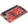
 SparkFun MicroMod ATP Carrier BoardSPARKFUN
¥6,298税込¥6,928
1個
33日以内出荷
DescriptionAccess all the pins(i.e. ATP)of the MicroMod Processor Boards with the SparkFun MicroMod ATP Carrier Board! This board breaks out the MicroMod Processor Board's pins on the M.2 connector to 0.1" spaced female headers and PTH pads on the edge of the board. This Carrier Board is great if you're interested in testing out different MicroMod Processor Boards for your application.A modern USB-C connector makes programming easy. In addition to the pins broken out, two separate Qwiic-enabled I2C ports allow you to easily daisy chain Qwiic-enabled devices. We've exposed the SWD pins for more advanced users who prefer to use the power and speed of professional tools. A USB-A connector is provided for Processor Boards that have USB Host support. A backup battery is provided for processor boards with RTC. If you need a "lot" of GPIO with a simple-to-program, ready for market module, the ATP is the fix you need. We've even added a convenient jumper to measure the current consumption for low power testing.MicroMod is a modular interface ecosystem that connects a microcontroller "processor board" to various "carrier board" peripherals. Utilizing the M.2 standard, the MicroMod standard is designed to easily swap out processors on the fly. Pair a specialized carrier board for the project you need with your choice of compatible processor!Get Started with the MicroMod ATP Carrier Board GuideFeaturesM.2 ConnectorOperating Voltage Range~3.3V to 6.0V(via VIN to AP7361C 3.3V Voltage Regulator)3.3V(via 3V3)Ports [1]1x USB type C1x USB type A Host2x Qwiic Enabled I2C1x CAN1x I2S2x SPI2x UARTs2x Dedicated Analog Pins2x Dedicated PWM Pins2x Dedicated Digital Pins12x General Purpose Input Output Pins1x SWD 2x5 header1mAh battery backup for RTCButtonsResetBootLEDsPower3.3VPhillips #0 M2.5x3mm screw included[1] Note:Depending on the design of the Processor Board, not all the pins may be accessible.
アズワン品番67-0423-18
 SparkFun MicroMod DIY Carrier Kit 5 packSPARKFUN
¥2,398税込¥2,638
1個
33日以内出荷
DescriptionThe great thing about open source is that while SparkFun has designed our own MicroMod carrier boards, that does not stop you from creating your very own MicroMod carrier board. The MicroMod DIY Carrier Kit includes five M.2 connectors(4.2mm height), screws, and standoffs so that you can get all the special parts you may need to make your own carrier board.MicroMod uses the common M.2 connector. This is the same connector found on modern motherboards and laptops. There are various locations for the plastic 'key' on the M.2 connector to prevent a user from inserting an incompatible device. The MicroMod standard uses the 'E' key and further modifies the M.2 standard by moving the mounting screw 4mm to the side. The 'E' key is fairly common so a user could insert a M.2 compatible Wifi module but because the screw mount doesn't align, the user would not be able to secure an incompatible device into a MicroMod carrier board.MicroMod is a modular interface ecosystem that connects a microcontroller "processor board" to various "carrier board" peripherals. Utilizing the M.2 standard, the MicroMod standard is designed to easily swap out processors on the fly. Pair a specialized carrier board for the project you need with your choice of compatible processor!
アズワン品番67-0424-52
 SparkFun I2S Audio Breakout - MAX98357ASPARKFUN
¥1,998税込¥2,198
1個
33日以内出荷
DescriptionThe SparkFun I2S Audio Breakout board uses the MAX98357A digital to analog converter(DAC), which converts I2S(not be confused with I2C)audio to an analog signal to drive speakers. The I2S Audio Breakout converts the digital audio signals using the I2S standard to an analog signal and amplifies the signal using a class D amplifier which can deliver up to 3.2W of power into a 4Ω load. The board can be configured to output only the left channel audio, right channel, or both.The SparkFun I2S Audio Breakout board is fairly simple, requiring only a few pin connections to get it up and working. By default the board is configured in "mono" operation, meaning the left and right signals are combined together to drive a single speaker. If you want a separate speaker for the left and right audio channels you'll need to cut the mono jumper. In addition to being able to select the audio channel output, the gain can also be configured in a few ways. The gain of the amplifier can be configured from as low as +3dB to as high as +15dB. While the channel selection can be configured on board, the gain however is controlled externally using the gain pin. By default, the board is configured for +9dB, but can be easily changed!Get Started with the SparkFun I2S Audio Breakout GuideFeaturesSupply Voltage Range:2.5V - 5.5V.Output Power:3.2W into 4Ω at 5V.Output Channel Selection:Left, Right, or Left/2 + Right/2(Default).Sample Rate:8kHz - 96kHz.Sample Resolution:16/32 bit.Quiescent Current:2.4mA.Filterless Class D OutputsNo MCLK RequiredClick and Pop ReductionShort-Circuit and Thermal Protection.
アズワン品番67-0422-64
 Shapeoko 4 XL - Hybrid Table, with RouterSPARKFUN
¥799,800税込¥879,780
1個
33日以内出荷
DescriptionPlease note, these machines are built to order have an estimated lead time of 4 business days before shippingThis is the Shapeoko 4 XL, nearly double the cutting area of the Shapeoko 4 Standard! The Shapeoko is a 3-axis CNC Machine kit that allows you to create your 2D and 3D designs out of non-ferrous metals, hardwoods, and plastics. The Shapeoko 4 XL is designed to be affordable enough for any shop and powerful enough to do real work. Don't let the size intimidate you! This is an entry-level CNC machine designed for hobbyists, artists, and fabricators!Each Shapeoko 4 XL has a cutting area of 838.2mm(X)x 444.5 mm(Y)x 101.6mm(Z)(33"×17.5"×4")and an overall footprint of 1270mm(X)x 609.6mm(Y)x 482.6mm(Z)(50"×24"×19"). The power cable included in this kit is designed for the United States National Plug Standard. Don't forget you can put whatever you want on the adapter ring(as long as it fits), whether that's a laser, 3D print extrusion head, or a marker. Get creative!Upgrades from the Shapeoko 3 include:New, more rigid v-wheel design15mm beltsInductive homing switchesNew electronicsIntegrated t-slot Hybrid Table(OPTIONAL)Fully-supported Y extrusionsLeadscrew-driven Z-axisNew, more rigid 65mm router mountSweepy 65mm V2 dust bootNote:This item is non-returnable. If this item arrives damaged or is not functioning properly, please do not hesitate to contact us to see if further actions may be taken.Not Compatible with the Shapeoko 4:Expansion PacksT-Track Clamp KitsZ-PlusProximity Switch KitMaintenance KitShapeoko 3 Bit SetterHDZ 4.0FeaturesFootprint:1270mm×609.6mm×482.6mm(50"×24"×19")Cutting Area:838.2mm×444.5mm×101.6mm(33"×17.5"×4")Weight 137lbs.Operating System:Mac(OSX 10.14 or higher)or PC(Windows 8.1 or 10, Intel or AMD)
アズワン品番67-0428-90
 PicoBuck LED DriverSPARKFUN
¥5,298税込¥5,828
1個
33日以内出荷
DescriptionThe PicoBuck LED Driver is an economical and easy to use driver that will allow you to control and blend three different LEDs on three different channels. By default, each channel is driven at 330mA; that current can be reduced by either presenting an analog voltage or a PWM signal to the board. Version 12 of the board adds a solderable jumper that can be closed to increase the maximum current to 660mA. The new voltage regulator also increased the voltage rating on the various components on the board, allowing it to be used up to the full 36V rating of the AL8805 part.Three signal inputs are provided for dimming control. You can use the PWM signal from an Arduino or your favorite microcontroller to dim each channel individually, or you can tie them all to the same PWM for simultaneous dimming. Dimming can be done by an analog voltage(20%-100% of max current by varying voltage from .5V-2.5V)or by PWM(so long as PWM minimum voltage is less than .4V and maximum voltage is more than 2.4V)for a full 0-100% range. A small jumper is provided for each channel to allow you to increase the drive strength from 330mA to 660mA. Two mounting holes for 4-40 or M3 screws are provided on either side of the board. They are perforated so they can be easily snapped off with a pair of pliers, if a smaller footprint is desired.Note:If you're going to use screw terminals, this board uses two different sizes. Check the related products for both sizes you'll need.Note:The PicoBuck LED Driver was made in collaboration with Ethan Zonca. A portion of each sale is given back to him.
アズワン品番67-0420-83
 SparkFun Digital Temperature Sensor - TMP102 QwiicSPARKFUN
¥2,298税込¥2,528
1個
33日以内出荷
DescriptionWe all like to know the temperature, right? Well, with the SparkFun TMP102 Digital Temperature Sensor, we've made it just about as easy as it gets. Based on the original Digital Temperature Sensor Breakout TMP102, we've added Qwiic connectors to bring this board into our plug-and-play Qwiic Ecosystem and added an address jumper instead of breaking out the address pin. However, we still have broken out 0.1"-spaced pins in case you prefer to use breadboard.The TMP102 itself is an easy-to-use digital temperature sensor from Texas Instruments. While some temperature sensors use an analog voltage to represent the temperature, the TMP102 uses the I2C bus of the Arduino to communicate the temperature.The TMP102 is capable of reading temperatures to resolution of 0.0625℃, and is accurate up to 0.5℃. The breakout has built-in 4.7kΩ pull-up resistors for I2C communications and runs from 1.4V to 3.6V. I2C communication uses an open drain signaling, so there is no need to use level shifting.The SparkFun Qwiic Connect System is an ecosystem of I2C sensors, actuators, shields and cables that make prototyping faster and less prone to error. All Qwiic-enabled boards use common 1mm pitch, 4-pin JST connector. This reduces the amount of required PCB space, and polarized connections mean you can't hook it up wrong.Get Started with the Qwiic TMP102 Digital Temperature Sensor GuideFeaturesUses the I2C interfaceI2C Address:0x48 by default(Three additional addresses available, as well)12-bit, 0.0625℃ resolutionTypical temperature accuracy of ±0.5℃3.3V sensorSupports up to four TMP102 sensors on the I2C bus at time2x Qwiic Connectors
アズワン品番67-0427-17
 SparkFun Beefy 3 - FTDI Basic BreakoutSPARKFUN
¥5,798税込¥6,378
1個
33日以内出荷
DescriptionThis is SparkFun Beefy 3 FTDI Basic Breakout for the FTDI FT231X USB to serial IC. The pinout of this board matches the FTDI cable to work with official Arduino and cloned 3.3V Arduino boards. It can also be used for general serial applications. Built upon the same foundation as our 3.3V SparkFun FTDI Basic Breakout, the Beefy 3 is equipped with an AP2112K voltage regulator making this FTDI basic breakout board capable of handling a current load of up to 600 mA! With the addition of a more "Beefy" voltage regulator your will now be able to power a 3.3V project directly from the FTDI. The pinout of this board matches the FTDI cable to work with official Arduino and cloned 3.3V Arduino boards.This board brings out the DTR pin as opposed to the RTS pin of the FTDI cable. The DTR pin allows an Arduino target to auto-reset when a new Sketch is downloaded. This is a really nice feature to have and allows a sketch to be downloaded without having to hit the reset button. This board will auto reset any Arduino board that has the reset pin brought out to a 6-pin connector. The pins labeled BLK and GRN correspond to the colored wires on the FTDI cable. The black wire on the FTDI cable is GND, green is DTR. Use these BLK and GRN pins to align the FTDI basic board with your Arduino target.There are pros and cons to the FTDI Cable vs the FTDI Basic. This board has TX and RX LEDs that allow you to actually see serial traffic on the LEDs to verify if the board is working, however this board now requires a Micro-B USB cable. The FTDI Cable is well protected against the elements, but is large and cannot be embedded into a project as easily. The FTDI Basic uses DTR to cause a hardware reset where the FTDI cable uses the RTS signal.This board was designed to decrease the cost of Arduino development and increase ease of use(the auto-reset feature rocks!). Our Arduino Pro and LilyPad boards use this type of connector.
アズワン品番67-0430-06
 SparkFun MicroMod Environmental Function BoardSPARKFUN
¥44,980税込¥49,478
1個
33日以内出荷
DescriptionThe SparkFun MicroMod Environmental Function Board adds additional sensing options to the MicroMod Processor Boards. This Function Board includes three sensors to monitor air quality(SGP40), humidity temperature(SHTC3), and CO2 concentrations(STC31)in your indoor environment. To make it even easier to use, all communication is over the MicroMod's I2C bus!The SGP40 measures the quality of the air in your room or house. The SGP40 uses a metal oxide(MOx)sensor with a temperature controlled micro hotplate and provides a humidity-compensated volatile organic compound(VOC)based indoor air quality signal. Both the sensing element and VOC Algorithm feature an unmatched robustness against contaminating gases present in real world applications enabling a unique long term stability as well as low drift and device to device variation.The SHTC3 is a highly accurate digital humidity and temperature sensor. The SHTC3 uses a capacitive humidity sensor with a relative humidity measurement range of 0 to 100% RH and bandgap temperature sensor with a temperature measurement range of -40℃ to 125℃. The SHTC3 builds on the success of their SHTC1 sensor with higher accuracy(±2% RH, ±0.2℃)than its predecessor, enabling greater flexibility.The STC31 measures CO2 concentrations based on thermal conductivity and has two CO2 measurement ranges:0 to 25 vol%; and 0 to 100 vol%. The measurement repeatability is 0.2 vol%, with a stability of 0.025 vol% / ℃. The measurement accuracy depends on the measurement range:0.5 vol% + 3% measured value; 1 vol% + 3% measured value. Using measurements from the SHTC3, the STC31 is able to provide humidity-compensated measurements together with improved temperature compensation. The STC31 can compensate for atmospheric pressure too - which is handy if, like us, you're up in the mountains!The outstanding performance of these three sensors is based on Sensirion's patented CMOSens(R)technology, which combines the sensor element, signal processing, and digital calibration on a small CMOS chip. The well-proven CMOS technology is perfectly suited for high-quality mass production and is the ideal choice for demanding and cost-sensitive OEM applications.Utilizing our handy M.2 MicroMod connector, no soldering is required to connect it to your system. Simply match up the key on your processor and function board's beveled edge connector to their respective key on the M.2 connector, then secure them to the main board with screws. The MicroMod Environmental Function Board can then be read via the I2C port. The board is equipped with the AP2112 3.3V voltage regulator, I2C pull-up resistors, power LED, jumper to disable the LED, and jumpers for alternative STC31 addresses.Note:A MicroMod Processor and Main Board are not included with this MicroMod Environmental Function Board. These boards will need to be purchased separately.MicroMod is a modular interface ecosystem that connects a microcontroller "processor board" to various "carrier board" peripherals. Utilizing the M.2 standard, the MicroMod standard is designed to easily swap out processors and function boards on the fly. Pair a specialized carrier board for the project you need with your choice of compatible processor!Get Started with the MicroMod Environmental Function BoardFeaturesInput voltage range2.5V to 6.0VTyp.5Vvia Main Board's USB connectorTyp.~3.7V to 4.2Vvia Main Board's LiPo battery ConnectorI/O voltage3.3VAP2112 3.3V voltage regulator(rated 600mA)Power LEDI2C pull-up resistorsSensirion SGP40 Air Quality SensorUses I2C interfaceAddress:0x59(default)Operating voltage range1.7V to 3.6V(Typ.3.3V)Operating temperature range-20℃ to +55℃Typical current consumption2.6mAduring continuous operation(at 3.3V)34μAwhen idle(heater off)Output signalDigital raw value(SRAW):0 - 65535 ticksDigital processed value(VOC Index):0 - 500 VOC index pointsSwitch-on behaviorTime until reliably detecting VOC events:<60sTime until specifications are met:<1hRecommended sampling intervalVOC Index:1sSRAW:0.5s - 10s(Typ. 1s)Sensirion SHTC3 Humidity and Temperature SensorUses I2C interfaceAddress:0x70(default, non-configurable)Operating voltage range1.62V - 3.6V(Typ.3.3V)Operating temperature range-40℃ to +125 ℃Relative HumidityMeasurement range:0% to 100%Typical accuracy:±2 %RHResolution:0.01 %RHTemperatureMeasurement range:-40℃ to +125 ℃Typical accuracy:±0.2 ℃Resolution:0.01 ℃Typical current consumption(varies based on mode)4.9μA to 430μA(Normal Mode)0.5μA to 270μA(Low Power Mode)Allows the STC31 to compensate for humidity and temperatureSensirion STC31 CO2 SensorUses I2C interfaceAddresses:0x29(default), 0x2A, 0x2B, 0x2COperating voltage range2.7V to 5.5V(Typ.3.3V)Operating temperature range-20 ℃ to +85 ℃Calibrated for CO2 in N2 and CO2 in airMeasurement ranges0 to 25 vol% in N20 to 100 vol% in airAccuracy0.5 vol% + 3% measured value in N21 vol% + 3% measured value in airConcentration and temperature resolution:16-bitRepeatability:0.2 vol%Temperature stability:0.025 vol% / ℃Start-up time:14 msThermal conductivity sensor provides calibrated gas concentration and temperature outputJumpersPWR LEDI2C pull-up resistorsSTC31 address selectionNote:The I2C addresses that are reserved for each sensor is 0x59(SGP40), 0x70(SHTC3), 0x29(STC31). A multiplexer/Mux is required to communicate to multiple SHTC3 sensors on a single bus. The SHTC3 uses the same address as the Qwiic Mux(0x70). For advanced users that are using multiple SHTC3's with the Qwiic Mux, you will need to adjust the Qwiic Mux's default address.
アズワン品番67-0427-60