カテゴリ
- 学童・教育用品(17)
- 制御機器(2)
- はんだ関連・静電気対策用品(1)
絞り込み
ブランド
- SPARKFUN
- モノタロウ(3)
- RS PRO(8)
- HAKKO(白光)(5)
- goot(太洋電機産業)(5)
- ホーザン(2)
- エンジニア(1)
- サンハヤト(1)
- DIGILENT(1)
- アズピュア(アズワン)(1)
「solder wick」の検索結果
特価

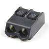
 Poke Home Connector - 2-PinSPARKFUN
¥189税込¥208
1個
33日以内出荷
DescriptionPoke Home Connectors have been featured on a number of our boards over the last few years by providing a simple screw-terminal-type connector for easy wire connection purposes. Similar to screw terminals, Poke Home Connectors grasp a wire entered into the receiving area of the pin-out by pressing down on the small plastic strip at the end of the housing. Doing so raises the internal clamp and, upon release of the button secures the wire in place without any soldering required.Poke Home Connectors work better in environments with a lot of vibrations(i.e. automotive applications)or when a wire is expanding or contracting due to temperature cycling. Additionally, the tension in the connector is automatically adjusted to the wire gauge(assuming it is within the accepted wire thickness)as opposed to variances in tension when a user tightens the screw terminal.
アズワン品番67-0425-83
 LEDドライバSPARKFUN
¥2,498税込¥2,748
1個
33日以内出荷
DescriptionThis is the FemtoBuck, a small-size single-output constant current LED driver. Each FemtoBuck has the capability to dim a single high-power channel of LEDs from 0-350mA at up to 36V while the dimming control can be either accessed via PWM or analog signal from 0-2.5V. This board is based off of the PicoBuck LED Driver, developed in collaboration with Ethan Zonca, except instead of blending three different LEDs on three different channels the FemtoBuck controls just one.For the FemtoBuck, we've increased the voltage ratings on the parts to allow the input voltage to cover the full 36V range of the AL8805 driver. Since the FemtoBuck is a constant current driver, the current drawn from the supply will drop as supply voltage rises. In general, efficiency of the FemtoBuck is around 95%, depending on the input voltage. On board each FemtoBuck you will find two inputs for both power input and dimming control pins and an area to install a 3.5mm screw terminal. Finally at either side of the board you will find small indents or "ears" which will allow you to use a zip tie to secure the wires to the board after soldering them down. This version of the FemtoBuck is equipped with a small solder jumper that can be closed with a glob of solder to double the output current from 330mA to 660mA.
アズワン品番67-0477-97
 SparkFun Configurable OpAmp Board - TSH82SPARKFUN
¥2,298税込¥2,528
1個
欠品中
DescriptionThe SparkFun TSH82 Configurable OpAmp Board was designed to give you the best combination of performance and flexibility that we could achieve by giving you two gain stages, each one independently accessible on the header pins. Each stage is natively configured as an inverting amplifier that can also be strung together to expand the capabilities of the TSH82 from STMicroelectronics. With the use of the jumpers on the back of the board, you can configure each stage for non-inverting operation, differential input, and DC input coupling.Electrically speaking, both stages on this board are identical. The default configuration is inverting with a gain of -4.7 with a bandwidth of almost 10MHz. Input signals are AC coupled, possess an input impedance of 10K with a low frequency cutoff of 15.9Hz. Outputs are also DC coupled, so don't forget to add a capacitor to the output if you're running a single-ended supply and need to strip out the DC component. The board will also operate with a single-ended DC power supply of 4.5V to 12V, or a bipolar supply from +/-2.25V to +/-6V.On the back of the board you'll find 10 solder jumpers that can be used to change the board's performance, but nothing there needs to be changed to use it in it's default state.Get Started With the Configurable OpAmp Board Guide
アズワン品番67-0420-03
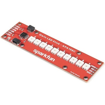 SparkFun Qwiic LED Stick - APA102CSPARKFUN
¥3,500税込¥3,850
1個
33日以内出荷
DescriptionThe SparkFun Qwiic LED Stick features ten addressable APA102 LEDs, making it easy to add full color LED control using I2C. Write to individual LEDs to display a count in binary, or write to the whole strip for cool lighting effects. You can even add more LEDs to the end if you need to. We've written an Arduino library and Python package that take care of the I2C and communication to the LEDs so all you have to do is decide what color each LED should be.The LED Stick has a default I2C address of 0x23 but can be changed with a simple command, allowing you to control up to 100 LEDs(10 Qwiic LED Sticks)on a single bus! The address can also be changed to 0x22 by closing the solder jumper on the back of the board.This board is one of our many Qwiic compatible boards! Simply plug and go. No soldering, no figuring out which is SDA or SCL, and no voltage regulation or translation required!Warning:Using a lot of LEDs can draw a lot of current. Make sure to consider the power limits of your setup. If you expect your LED chain to draw more than 600mA of current, connect your external supply directly to VLED. Closing the jumper from VLED to VCC will add a 4.7uF decoupling capacitor.The SparkFun Qwiic Connect System is an ecosystem of I2C sensors, actuators, shields and cables that make prototyping faster and less prone to error. All Qwiic-enabled boards use a common 1mm pitch, 4-pin JST connector. This reduces the amount of required PCB space, and polarized connections mean you can't hook it up wrong.Get Started with the Qwiic LED Stick GuideFeatures10x APA102C addressable LEDs driven by an ATTiny85Default I2C Address:0x23(Adjustable to 0x22 via Jumper)2x Qwiic Connectors
アズワン品番67-0421-83
 SparkFun Spectral Sensor Breakout - AS7263 NIR QwiicSPARKFUN
¥9,998税込¥10,998
1個
欠品中
DescriptionThe SparkFun AS7263 Near Infrared(NIR)Spectral Sensor Breakout brings spectroscopy to the palm of your hand, making it easier than ever to measure and characterize how different materials absorb and reflect different wavelengths of light. The AS7263 Breakout is unique in its ability to communicate by both an I2C interface and serial interface using AT commands. Hookup is easy, thanks to the Qwiic connectors attached to the board --- simply plug one end of the Qwiic cable into the breakout and the other into one of the Qwiic shields, then stack the board on a development board. You'll be ready to upload a sketch to start taking spectroscopy measurements in no time.The AS7263 spectrometer detects wavelengths in the visible range at 610, 680, 730, 760, 810 and 860nm of light, each with 20nm of full-width half-max detection. The board also has multiple ways for you to illuminate objects that you will try to measure for a more accurate spectroscopy reading. There is an onboard LED that has been picked out specifically for this task, as well as two pins to solder your own LED into.Note:The I2C address of the AS7263 is 0x49 and is hardware defined. A multiplexer/Mux is required to communicate to multiple AS7263 sensors on a single bus. If you need to use more than one AS7263 sensor consider using the Qwiic Mux Breakout.The SparkFun Qwiic Connect System is an ecosystem of I2C sensors, actuators, shields and cables that make prototyping faster and less prone to error. All Qwiic-enabled boards use a common 1mm pitch, 4-pin JST connector. This reduces the amount of required PCB space, and polarized connections mean you can't hook it up wrong.Get Started with the SparkFun AS726X Spectral Sensor Breakout GuideFeatures6 near-IR channels:610nm, 680nm, 730nm, 760nm, 810nm and 860nm, each with 20nm FWHMNIR filter set realized by silicon interference filters16-bit ADC with digital accessProgrammable LED drivers2.7V to 3.6V with I2C interface2x Qwiic connectors
アズワン品番67-0426-70
 SparkFun Real Time Clock Module - RV-1805 QwiicSPARKFUN
¥7,798税込¥8,578
1個
33日以内出荷
DescriptionGet with the times, already! This SparkFun Real Time Clock(RTC)Module is a Qwiic-enabled breakout board for the RV-1805 chipset. The RTC is ultra-low power(running at only about 22nA in its lowest power setting)so it can use a supercapacitor for backup power instead of a normal battery. This means you get plenty of charge and discharge cycles without any degradation to the "battery." To make it even easier to get your readings, all communication is enacted exclusively via I2C, utilizing our handy Qwiic system so no soldering is required to connect it to the rest of your system. However, we still have broken out 0.1"-spaced pins in case you prefer to use a breadboard.This RTC module's built in RV-1805 has not one, but two internal oscillators:a 32.768kHz tuning fork crystal and a low power RC based oscillator and can automatically switch between the two using the more precise crystal to correct the RC oscillator every few minutes. This feature allows the module to maintain a very accurate date and time with the worst case being +/- about three minutes over a year. The RV-1805 also has a built in trickle charger so as soon as the RTC is connected to power the it will be fully charged in under 10 minutes and has the ability to switch power to other systems allowing it to directly turn on or off a power hungry device such as a microcontroller or RF engine.There is also the option to add a battery to the board if the supercapacitor just isn't going keep your project powered long enough(keep in mind, the supercap can hypothetically make the board keep time for around 35 days), you can solder on an external battery. That means you can let board sit with no power or connection to the outside world and the current hour/minute/second/date will be maintained.Note:The I2C address of the RV-1805 is 0x69 and is hardware defined. A multiplexer/Mux is required to communicate to multiple RV-1805 sensors on a single bus. If you need to use more than one RV-1805 sensor consider using the Qwiic Mux Breakout.The SparkFun Qwiic connect system is an ecosystem of I2C sensors, actuators, shields and cables that make prototyping faster and less prone to error. All Qwiic-enabled boards use a common 1mm pitch, 4-pin JST connector. This reduces the amount of required PCB space, and polarized connections mean you can't hook it up wrong.Get Started with the RV-1805 Real Time Clock Module GuideFeaturesOperating Voltage(Startup):1.6V - 3.6VOperating Voltage(Timekeeping):1.5V - 3.6VOperating Temperature:-40℃ - 85℃Time Accuracy:±2.0 ppmCurrent Consumption:22nA(Typ.)I2C Address:0xD2Supercapacitor for Backup Power2x Internal Oscillators2x Qwiic Connectors
アズワン品番67-0420-02
 Arduino Nano Stackable Header KitSPARKFUN
¥849税込¥934
1個
欠品中
DescriptionThese stackable headers are made to work with the SparkFun Qwiic Shield for Arduino Nano or any comparable shield to connect the shield with a Arduino Nano footprint. This set includes two 15-pin headers; the pins are spaced by 0.1".Each set of headers allows you to stack a Qwiic Nano shield on top of your Arduino Nano or plug them into a solderless breadboard.Note:Soldering is required for functionality and physical attachment to a shield or board.
アズワン品番67-0425-81
 SparkFun Basic 16x2 Character LCD - White on Black, 5V with HeadersSPARKFUN
¥7,198税込¥7,918
1個
欠品中
DescriptionThis is a basic 16 character by two line display with a snazzy black background with white characters. This LCD utilizes the extremely common HD44780 parallel interface chipset. Interface code is freely available. This is the same LCD that is included with the SparkFun Inventor's Kit and comes with all the GPIO pins pre-soldered on for quick and easy interfacing.Includes white LED backlight.Get Started with the Basic Character LCD GuideFeatures3.15"×1.425"
アズワン品番67-0425-06
 Thumb Joystick - DeluxeSPARKFUN
¥1,098税込¥1,208
1個
33日以内出荷
DescriptionThis is a 16mm deluxe thumb joystick and is very similar to the 'analog' joysticks found inside PlayStation controllers. Directional movements are provided simply by two potentiometers - one for each axis. These 10k potentiometers will read the position changes for the joystick's full range of physical motion. This joystick also has a select button that is actuated when the joystick is pressed down.The mechanical parts found in this joystick are mostly metal and are considered far sturdier(rugged, if you will)than other, plastic joystick options.Note:This thumb joystick does not include a top cap and it will need to be purchased separately. Additionally, the leads on the housing of this joystick are much thicker than the leads on the trimpots &; push button components. When soldering to BOB-9110, we recommend using a pair of fine tip tweezers to guide each pin into the correct hole before pushing down.
アズワン品番67-0421-49
 SparkFun Wireless Joystick KitSPARKFUN
¥13,980税込¥15,378
1個
33日以内出荷
DescriptionThe SparkFun Wireless Joystick Kit provides an easy way to control your next XBee project. Before the wireless joystick, radio-controlled projects used hobby RC transmitters, the same ones used for RC cars, boats and planes. The problem with these transmitters is that many aren't customizable, and the ones that are tend to be too expensive for many of us. The Wireless Joystick Kit offers a custom wireless solution for those who want to control their project their own way.Equipped with the increasingly popular SAMD21 onboard, all you need is to assemble the SparkFun Wireless Joystick into the configuration you want and add your own XBee and lithium ion battery into the provided sockets. The Wireless Joystick Kit can be assembled into a configuration that utilizes dual joysticks for better RC steering robots(like tanks)or a single joystick configuration with four 12mm momentary pushbuttons(a setup similar to what older game consoles used). We have provided a full Hookup Guide that gives assembly instructions, as well as a tank-steering motor controller tutorial to help get you started!Please be aware that the SparkFun Wireless Joystick Kit isNOT supported on Windows 7/8due to a lack of support drivers for those specific OS's.Note:This kit will need to be assembled before use, so a beginner's knowledge of soldering will be required. Additionally, in an effort to keep shipping rates down and make this kit available to people throughout the world without delay, there is no XBee or lithium ion battery included.Get Started with the Wireless Joystick Kit Guide
アズワン品番67-0424-08
 SparkFun Qwiic micro:bit BreakoutSPARKFUN
¥1,898税込¥2,088
1個
33日以内出荷
DescriptionThe SparkFun Qwiic micro:bit Breakout is a board that connects to the BBC micro:bit and expands the capabilities of the development platform by providing access to more pins and allowing for connections to the I2C and SPI buses. This breakout board for the micro:bit's edge connector allows intermediate and advanced users to connect the micro:bit to breadboards and other Qwiic sensors, motors, LEDs and more.The micro:bit on its own has three digital/analog input/output rings available for you to use initially with alligator clips. With the micro:bit Breakout we have broken out all 21 GPIO, power and ground-to-pin outs in a 0.1" formation and with two individual Qwiic Connectors. With this breakout you will be able to unlock the full potential of your micro:bit!Note:No micro:bit or headers are included with this breakout; they will need to be purchased separately. If you would like a micro:bit breakout with headers already soldered on, be sure to check out this board's sibling.The SparkFun Qwiic Connect System is an ecosystem of I2C sensors, actuators, shields and cables that make prototyping faster and less prone to error. All Qwiic-enabled boards use a common 1mm pitch, 4-pin JST connector. This reduces the amount of required PCB space, and polarized connections mean you can't hook it up wrong.Get Started with the Qwiic micro:bit Breakout Guide
アズワン品番67-0420-12
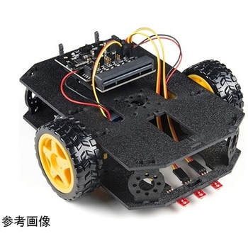 SparkFun micro:bot kit for micro:bit - v2.0SPARKFUN
¥24,980税込¥27,478
1個
33日以内出荷
DescriptionRobots are fun, and the micro:bit is the perfect controller for learning how to build and program robots! Combining the micro:bit with the SparkFun moto:bit carrier board creates a flexible, low-cost, Qwiic-enabled robotics platform for robot enthusiasts young and old! With the SparkFun micro:bot kit you will be able to create simple robots quickly without spending hours learning how to build and program your bot.Inside each micro:bot kit you will find all the components required to build your micro:bit into a robotics powerhouse; the only part that's not included is the micro:bit itself. Simply add your own micro:bit to the provided moto:bit, assemble the kit, and you will be ready to start moving. The SparkFun micro:bot kit is a great way to get your feet wet in the world of robotics.The kit does not require any soldering and is recommended for anyone curious about robotics or the micro:bit platform.Note:The SparkFun micro:bot kit doesNOTinclude a micro:bit board. The micro:bit board will need to be purchased separately.The micro:bit is a pocket-sized computer that lets you get creative with digital technology. Between the micro:bit and our shield-like bit boards you can do almost anything while coding, customizing and controlling your micro:bit from almost anywhere! You can use your micro:bit for all sorts of unique creations, from robots to musical instruments and more. At half the size of a credit card, this versatile board has vast potential!Get started with the micro:bot kit Guide
アズワン品番67-0424-41
 SparkFun High Precision Temperature Sensor - TMP117 QwiicSPARKFUN
¥4,898税込¥5,388
1個
33日以内出荷
DescriptionThe SparkFun Qwiic TMP117 breakout is a high precision temperature sensor equipped with an I2C interface. It outputs temperature readings with high precision of ±0.1℃ across the temperature range of -20℃ to +50℃s with no calibration and a maximum range from -55℃ to 150℃. The SparkFun High Precision Temperature Sensor also has a very low power consumption rate which minimizes the impact of self-heating on measurement accuracy. Utilizing our handy Qwiic system, no soldering is required to connect it to the rest of your system. However, we still have broken out 0.1"-spaced pins in case you prefer to use a breadboard.The SparkFun High Precision Temperature Sensor also includes programmable temperature limits, and digital offset for system correction. While the TMP102 is capable of reading temperatures to a resolution of 0.0625℃ and is accurate up to 0.5℃, the on-board TMP117 is not only more precise but has a 16-bit resolution of 0.0078℃!To make this breakout even easier to use, we've written an Arduino library to help you get started "Qwiic-ly." Check the Documents tab above for more information.The SparkFun Qwiic Connect System is an ecosystem of I2C sensors, actuators, shields and cables that make prototyping faster and less prone to error. All Qwiic-enabled boards use a common 1mm pitch, 4-pin JST connector. This reduces the amount of required PCB space, and polarized connections mean you can't hook it up wrong.The TMP117 High Precision Temperature Sensor can also be automatically detected, scanned, configured, and logged using the OpenLog Artemis datalogger system. No programming, soldering, or setup required!Need a custom board? This component can be found in SparkFun's A La Carte board builder. You can have a custom design fabricated with this component - and your choice of hundreds of other sensors, actuators and wireless devices - delivered to you in just a few weeks.Get Started with the SparkFun High Precision TMP117 Hookup GuideFeaturesUses I2C interface(Qwiic-enabled)Four selectable addresses0x48(default), 0x49, 0x4A, 0x4B16-bit resolution, 0.0078℃High accuracy, digital temperature sensor±0.1℃(max)from ?20℃ to 50℃±0.15℃(max)from ?40℃ to 70℃±0.2℃(max)from ?40℃ to 100℃±0.25℃(max)from ?55℃ to 125℃±0.3℃(max)from ?55℃ to 150℃Operating temperature range-55℃ to +150℃Operating voltage range1.8V to 5.5VTypically 3.3V if using the Qwiic cableLow power consumption3.5μA(1-Hz conversion cycle)150nA(shutdown current)Programmable operating modesContinuous, one-shot, and shutdownProgrammable temperature alert limitsSelectable averaging for reduced noiseDigital offset for system correctionNIST traceabilityDocumentsSchematicEagle FilesBoard DimensionsHookup GuideDatasheet(TMP117)Arduino LibraryGitHub Hardware Repo
アズワン品番67-0427-10
 PicoBuck LED DriverSPARKFUN
¥5,298税込¥5,828
1個
33日以内出荷
DescriptionThe PicoBuck LED Driver is an economical and easy to use driver that will allow you to control and blend three different LEDs on three different channels. By default, each channel is driven at 330mA; that current can be reduced by either presenting an analog voltage or a PWM signal to the board. Version 12 of the board adds a solderable jumper that can be closed to increase the maximum current to 660mA. The new voltage regulator also increased the voltage rating on the various components on the board, allowing it to be used up to the full 36V rating of the AL8805 part.Three signal inputs are provided for dimming control. You can use the PWM signal from an Arduino or your favorite microcontroller to dim each channel individually, or you can tie them all to the same PWM for simultaneous dimming. Dimming can be done by an analog voltage(20%-100% of max current by varying voltage from .5V-2.5V)or by PWM(so long as PWM minimum voltage is less than .4V and maximum voltage is more than 2.4V)for a full 0-100% range. A small jumper is provided for each channel to allow you to increase the drive strength from 330mA to 660mA. Two mounting holes for 4-40 or M3 screws are provided on either side of the board. They are perforated so they can be easily snapped off with a pair of pliers, if a smaller footprint is desired.Note:If you're going to use screw terminals, this board uses two different sizes. Check the related products for both sizes you'll need.Note:The PicoBuck LED Driver was made in collaboration with Ethan Zonca. A portion of each sale is given back to him.
アズワン品番67-0420-83
 SparkFun Inventor's Kit for micro:bit v2 Lab PackSPARKFUN
¥159,800税込¥175,780
1個
33日以内出荷
DescriptionThe SparkFun Inventor's Kit for micro:bit v2 Lab Pack includes 10 complete micro:bit v2 Inventor's Kits, an SIK Refill Pack and 25 AAA-sized batteries to get your students started in the world of electronics. The SIKs inside the Lab Pack have everything you need, including micro:bit v2s, connector breakouts, breadboards and all the cables and accessories to hook up all the projects listed in our online Experiment Guide.The kit does not require any soldering and is recommended for all users, from beginners to engineering students. We have provided a complete Experiment Guide in the Documents tab for you to check out now! If you are new to teaching electronics or have taught with the original SparkFun Inventor's Kit and are looking for something new, the SIK for micro:bit v2 is the perfect kit for you!SparkFun packages everything educators need to get started with this platform in a variety of classroom and makerspace settings with diverse student populations. The hardware boards, cables and extra parts come pre-packaged, and our online support materials --- including an online Experiment Guide(to be updated)--- help you bring the power of the open source community to your classroom. Examples and curriculum materials are available from SparkFun and Arduino, as well as from other educators involved in this growing maker movement.The micro:bit is a pocket-sized computer that lets you get creative with digital technology. Between the micro:bit and our shield-like bit boards you can do almost anything while coding, customizing and controlling your micro:bit from almost anywhere! You can use your micro:bit for all sorts of unique creations, from robots to musical instruments and more. At half the size of a credit card, this versatile board has vast potential!
アズワン品番67-0424-93
 SparkFun Real Time Clock Module - RV-8803 QwiicSPARKFUN
¥5,798税込¥6,378
1個
33日以内出荷
DescriptionThe SparkFun RV-8803 Real Time Clock Module is a Qwiic-enabled breakout board for the RV-8803 RTC. The RV-8803 boasts some impressive features including a temperature compensated crystal providing extremely precise time-keeping, low power consumption, and time stamp event input along with a user-programmable timing offset value. The RV-8803 also has an improved I2C interface compared to the RV-1805 RTC that removes the need to sequence commands/writes to the device. Best of all, the temperature compensation comes factory calibrated. Utilizing our handy Qwiic system so no soldering is required to connect it to the rest of your system. However, we still have broken out 0.1"-spaced pins in case you prefer to use a breadboard.Adding a real-time clock to your project is the perfect way to get more accurate data; timing or otherwise. Using the Qwiic connector makes for a fast, solid way to incorporate this into your project. The RTC module has counters for hundredths of seconds, seconds, minutes, hours, date, month, year and weekday with a number of alarm and interrupt settings available as well. Plus the large operating temperature range(-40 to +105℃)and temperature compensated crystal makes for a good addition for field applications or harsh environments.The SparkFun Qwiic Connect System is an ecosystem of I2C sensors, actuators, shields and cables that make prototyping faster and less prone to error. All Qwiic-enabled boards use a common 1mm pitch, 4-pin JST connector. This reduces the amount of required PCB space, and polarized connections mean you can't hook it up wrong.Get Started with the SparkFun RV-8803 Real Time Clock Module GuideFeaturesFactory Calibrated Temperature CompensationHigh Time Accuracy±1.5 ppm 0 to +50℃±3.0 ppm -40 to +85℃±7.0 ppm +85 to +105℃1.5V to 5.5V Operating Voltage Range240nA @ 3.3v Low-Power ConsumptionI2C Address:0x32Periodic Countdown Timer Interrupt functionPeriodic Time Update Interrupt function(seconds, minutes)Alarm Interrupts for weekday or date, hour and minute settingsExternal Event Input with Interrupt and Time Stamp functionProgrammable Clock Output pin for peripheral devices.Operating temperature range:-40 to +105℃2x Qwiic Connectors
アズワン品番67-0420-10
 LOAD CELL AMP HX711SPARKFUN
¥3,500税込¥3,850
1個
欠品中
DescriptionThe SparkFun Load Cell Amplifier is a small breakout board for the HX711 IC that allows you to easily read load cells to measure weight. By connecting the amplifier to your microcontroller you will be able to read the changes in the resistance of the load cell, and with some calibration you'll be able to get very accurate weight measurements. This can be handy for creating your own industrial scale, process control or simple presence detection.This version of the SparkFun Load Cell Amplifier features a few changes that you specifically asked for! We have separated the analog and digital supply, as well as added a 3.3uH inductor and a 0.1uF filter capacitor for digital supply. Need even more? Checkout the SparkFun Qwiic Scale. It has all the features of the HX711 but with additional library support, a true I2C interface, and no soldering required!The HX711 uses a two-wire interface(Clock and Data)for communication. Any microcontroller's GPIO pins should work, and numerous libraries have been written, making it easy to read data from the HX711. Check the hookup guide below for more information.Load cells use a four-wire Wheatstone bridge configuration to connect to the HX711. These are commonly colored RED, BLK, WHT, GRN and YLW. Each color corresponds to the conventional color coding of load cells:Red(Excitation+ or VCC)Black(Excitation- or GND)White(Amplifier-, Signal- or Output-)Green(A+, S+ or O+)Yellow(Shield)The YLW pin acts as an optional input that is not hooked up to the strain gauge but is utilized to ground and shield against outside EMI(electromagnetic interference). Please keep in mind that some load cells might have slight variations in color coding.Note:Special thanks to Bodge for supplying the Library for the HX711!Get Started with the HX711 Load Cell Amplifier GuideFeaturesOperation Voltage:2.7V--5VOperation Current:< 1.5mASelectable 10SPS or 80SPS output data rateSimultaneous 50 and 60Hz supply rejection
アズワン品番67-0362-17
 Garmin LIDAR-Lite v4 LED - Distance Measurement SensorSPARKFUN
¥21,980税込¥24,178
1個
33日以内出荷
DescriptionThe LIDAR-Lite v4 LED sensor is the next step in the LIDAR-Lite line. A small, lightweight, low-power optical ranging sensor. It's the first to incorporate ANT profile wireless networking technology into an optical sensor. Its built-in nRF52840 processor means that developers can create custom applications, or be operated as a stand-alone device right out of the box by using the preloaded stock application.Like the LIDAR-Lite v3 and LIDAR-Lite v3HP sensors; it can also be directly connected to an external micro-controller running a custom user application. As such, it provides a highly adaptable option for OEM and maker applications in robotics, Internet of Things, and unmanned vehicles ― or any application where an ultrasonic sensor might otherwise be used. It's perfect as the basic building block for applications where wireless capabilities, small size, light weight, low power consumption and high performance are important factors in a short-range, 10-meter, optical distance measuring sensor.The LIDAR-Lite v4 requires an external 5VDC power source and soldering is required. This Time-of-Flight ranging module uses a LED and optics for ranging. It does not use a laser; therefore, it is inherently eye-safe under normal usage.FeaturesResolution:1 cmMeasurement repeatability:As measured indoors to a 90% reflective target1 cm is equivalent to 1 standard deviationUsing "high accuracy" mode, with averaging:+/- 1 cm to 2 meters+/- 2 cm to 4 meters+/- 5 cm to 10 metersRange:5 cm to 10 meters(as measured from back of unit)Update rate:I2C = >200 Hz typicalANT(R)= up to 200 Hz to a 90% target indoors at 2m in normal operating modeInterface:I2C or ANT; user configurable for SPI using the Nordic SDKPower(operating voltage):4.75 - 5.25 VDCCurrent consumption:2mA idle, 85mA during acquisitionOperating temperature:-20 to 60° CLED wavelength:940 nmBeam divergence:4.77°Optical aperture:14.9 mmUnit size(HxWxD):2.1"×0.8"×0.9"(52.2×21.2×24.0 mm)Weight:14.6 g(0.5 oz)
アズワン品番67-0427-09
 SparkFun Qwiic Alphanumeric Display - WhiteSPARKFUN
¥2,998税込¥3,298
1個
33日以内出荷
DescriptionWe are quite familiar with seven-segment displays. We see them on our alarm clocks, ovens, and microwaves. By adding more segments to each digit you can display more than just numbers! Introducing the brand new SparkFun Qwiic Alphanumeric Display. These white fourteen-segment digits allow you display all sorts of numbers, characters, and symbols. With Qwiic, simply plug it in and go. No soldering, no figuring out which is SDA or SCL, and no voltage regulation or translation required!The SparkFun Alphanumeric Display Arduino library makes printing strings to the display as easy as calling the print()function. With this library, you'll be able to send I2C commands to the VK16K33 LED driver chip to light up segments(including the decimal point or colon)and even scroll your string across the display. You can download the library through the Arduino library manager by searching 'SparkFun Alphanumeric Display' or you can get the GitHub repo as a .zip file and install the library from there.The VK16K33 also supports I2C address configuration. Simply close a combination of the address jumpers on the back and you can communicate with up to four displays on the same bus. Our slim board design also features detachable stand off holes, vertical Qwiic connectors, and internal mounting holes.The SparkFun Qwiic Connect System is an ecosystem of I2C sensors, actuators, shields and cables that make prototyping faster and less prone to error. All Qwiic-enabled boards use a common 1mm pitch, 4-pin JST connector. This reduces the amount of required PCB space, and polarized connections mean you can't hook it up wrong.Get Started with the Qwiic Alphanumeric Display Hookup GuideFeaturesWhite displayOperating Voltage:3.3VIntegrated RC oscillatorMaximum display segment numbers:128 patterns13×3 matrix key scan circuit16-step dimming circuitI2C Addresses:0x70(0x71, 0x72, 0x73)2x Qwiic connectors2x Wall Mounting Points
アズワン品番67-0421-87