カテゴリ
- 学童・教育用品(56)
- 制御機器(2)
絞り込み
ブランド
- SPARKFUN
- モノタロウ(3)
- MAZDA(マツダ)(82)
- 光(49)
- 大阪魂(49)
- ダイヤトレンド(47)
- オカムラ(岡村製作所)(42)
- ヤマモトレーシング(27)
- 島津製作所(16)
- C’ultiva(カルティバ)(14)
- ASUS(エイスース)(13)
- NTN(エヌティーエヌ)(11)
- Intel(インテル)(10)
- TRUSCO(8)
- フエニックス・コンタクト(8)
- SCHMERSAL(8)
- アイリスオーヤマ(7)
- MUELLER ELECTRIC(7)
- メディアカバーマーケット(7)
- AbuGarcia(アブガルシア)(7)
- ブランドをもっと見る
「up4」の検索結果
 SparkFun Triple Axis Digital Accelerometer Breakout - ADXL313 QwiicSPARKFUN
¥6,598税込¥7,258
1個
欠品中
DescriptionThe SparkFun ADXL313 Breakout is a low power, high resolution(up to 13-bits)3-axis accelerometer for measurement up to ±4g. This breakout measures the static acceleration of gravity in tilt-sensing applications, as well as dynamic accel
アズワン品番67-0427-42
 ATX Right Angle Connector - PTH 4-pinSPARKFUN
¥209税込¥230
1個
33日以内出荷
DescriptionThis 4-pin, ATX, right angle connector mates up to the standard 4-pin computer peripheral port often found on ATX power supplies. This connector will also serve as a replacement to that found in the SparkFun ATX Power Connector Breakout Kit.FeaturesWorks with 12V 5V devices.
アズワン品番67-0425-74
 Micro HDMI Cable - 3ftSPARKFUN
¥2,998税込¥3,298
1個
欠品中
DescriptionThis is an inexpensive 3-foot-long HDMI to Micro HDMI cable that you can use to hook up your Raspberry Pi 4 to a suitable monitor or TV. Heck, you can hook up anything you want with it! Micro HDMI is less common of a medium right now even m
アズワン品番67-0420-59
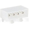
 Screw Terminals 3.5mm Pitch 4-PinSPARKFUN
¥529税込¥582
1個
欠品中
DescriptionThis is a Screw Terminal with 3.5mm pitch pins. Comes in 2, 3, or 4 positions and have the really cool feature of slide-locking together to form any size you need(4, 5, up to 20 without problems). Rated up to 300V @ 10A. Terminal can accept 26 to 16AWG wire. 3.5mm/138mil pin pitch will not fit standard 0.1" perf boards but this is the most common pitch screw terminal.
アズワン品番67-0425-71
 AVR 8 Pin 20MHz 8K 4A/D - ATtiny85SPARKFUN
¥1,098税込¥1,208
1個
33日以内出荷
DescriptionAtmel's itty-bitty ATtiny85 8-Bit Processor. 8K of program space, 6 I/O lines, and 4-channel 10 bit ADC. Runs up to 20MHz with external crystal. Package can be programmed in circuit.
アズワン品番67-0430-03
 SparkFun Raspberry Pi 4 Hardware Starter Kit - 4GBSPARKFUN
¥56,980税込¥62,678
1個
33日以内出荷
DescriptionThe Raspberry Pi 4 Hardware Starter Kit provides a solid set of parts and instruction for working with the Raspberry Pi 4 in a more hardware-centric manner. While the Raspberry Pi isn't typically considered a go-to for hardware projects, its I/O pins hold a lot of benefits that you can use for a variety of applications. This kit covers the basics like using LEDs, and Buttons while providing a solid set of parts for working with any other hardware I/O and the 40-pin header. In addition, we've included all the parts needed for getting the Raspberry Pi 4 up and running whether it's on its own, or using a monitor(not included). The new 64GB MicroSD cards keep read/write commands running super fast, too.Most of the contents of the kit rely on the use of the 2x20, 40-pin header, so we've included a special extender to allow you to plug in the ribbon cable while using the provided heatsink case. We've also included a Qwiic Shim for easily working with I2C based Qwiic boards with the Pi. No soldering is required for this kit!Note:This variation includes the 4GB RAM option for the Raspberry Pi 4.Get Started with the Raspberry Pi 4 Model B Guide
アズワン品番67-0424-46
 LilyPad Sewable Electronics Kit GuidebookSPARKFUN
¥2,098税込¥2,308
1個
33日以内出荷
DescriptionThe full-color LilyPad Sewable Electronics Kit Guidebook contains step-by-step instructions for creating four interactive projects from the materials contained in the kit. Examples and circuits are provided and explained. The manual also includes a glossary and troubleshooting tips. Once you make your way through all of the projects, you will have a much better grasp on e-textiles!Note:This is just the manual for the LilyPad Sewable Electronics Kit. The kit itself or the individual parts used in this book will need to be purchased separately.ExamplesProject 1:Glowing PinProject 2:Illuminated MaskProject 3:Light-Up PlushProject 4:Night-Light Pennant
アズワン品番67-0420-18
 Flexible Qwiic Cable - 50mmSPARKFUN
¥469税込¥516
1個
33日以内出荷
DescriptionThis is a 50mm long 4-conductor cable with 1mm JST termination. It's designed to connect Qwiic enabled components together but can be used for other applications as well. The cable insulation is made from a highly malleable material making it more flexible than our original Qwiic cable particularly in tight spaces or enclosures.Each Qwiic Cable's wires have been color coded to red, black, blue and yellow.The SparkFun Qwiic connect system is an ecosystem of I2C sensors, actuators, shields and cables that make prototyping faster and less prone to error. All Qwiic-enabled boards use a common 1mm pitch, 4-pin JST connector. This reduces the amount of required PCB space, and polarized connections mean you can't hook it up wrong.FeaturesDimensions:50mm(1.96")Length
アズワン品番67-0426-06
 Himax CMOS Imaging Camera - HM01B0SPARKFUN
¥3,698税込¥4,068
1個
33日以内出荷
DescriptionThe HM01B0 from Himax Imaging is an ultra low power CMOS Monochrome Image Sensor that enables the integration of an "Always On" camera for computer vision applications such as gestures, intelligent ambient light and proximity sensing, tracking and object identification. The sensor allows the sensor to consume very low power of <2mW at QVGA 30FPS. This low power consumption and vision applications camera comes with a ribbon cable that mates to the camera connector populated on the following products:MicroMod Machine Learning Carrier BoardArtemis Development KitEdge Development Board - Apollo3 BlueThe HM01B0 contains 320×320 pixel resolution and supports a 320×240 window mode which can be readout at a maximum frame rate of 60FPS, and a 2×2 monochrome binning mode with a maximum frame rate of 120FPS. The video data is transferred over a configurable 1bit, 4bit or 8bit interface with support for frame and line synchronization. The sensor integrates black level calibration circuit, automatic exposure and gain control loop, self-oscillator and motion detection circuit with interrupt output to reduce host computation and commands to the sensor to optimize the system power consumption.FeaturesImage SensorUltra Low Power Image Sensor(ULPIS)designed for Always On vision devices and applicationsHigh sensitivity 3.6μ BrightSenseTM pixel technology320×320 active pixel resolution with support for QVGA window, vertical flip and horizontal mirror readoutProgrammable black level calibration target, frame size, frame rate, exposure, analog gain(up to 8x)and digital gain(up to 4x)Automatic exposure and gain control loop with support for 50 / 60Hz flicker avoidanceFlexible 1bit, 4bit and 8bit video data interface with video frame and line syncMotion Detection circuit with programmable ROI and detection threshold with digital output to serve as an interruptOn-chip self oscillatorI2C 2-wire serial interface for register accessHigh CRA for low profile module designSensor ParametersActive Pixel Array 320×320Pixel Size 3.6 μm×3.6 μmFull Image Area 1152 μm×1152 μmDiagonal(Optical Format)1.63 mm(1/11″)Scan Mode:ProgressiveShutter Type:Electronic Rolling ShutterFrame Rate MAX 51 fps @ 320×320, 60 fps @ 320×240(QVGA)CRA(maximum)30℃Sensor SpecificationsSupply Voltage:Analog - 2.8 V, Digital - 1.5V(Internal LDO:1.5V - 2.8V), I/O - 1.5 - 2.8VInput Reference Clock:3 - 50 MHzSerial Interface(I2C):2-wire, 400 KHz max.Video Data Interface:1b, 4b, 8b with frame / line SYNCOutput Clock Rate MAX:50 MHz for 1bit, 12.5 MHz for 4bit, 6.25 MHz for 8bitEst. Power Consumption(include IO with 5pF load):QVGA 60FPS(Typical)<4 mWQVGA 30FPS(Typical)<2 mW
アズワン品番67-0427-08
 LilyPad Sewable Electronics KitSPARKFUN
¥31,980税込¥35,178
1個
33日以内出荷
DescriptionThe LilyPad Sewable Electronics Kit lets you explore the wonderful world of electronic sewing(e-sewing)and e-textiles through a series of introductory projects using the LilyPad system. You'll learn how to sew basic circuits to light up LEDs, control them with buttons and switches and even experiment with a pre-programmed LilyMini circuit that reacts to ambient light levels. In addition to LilyPad LEDs and battery holders, the kit comes with two LilyPad ProtoSnap boards that let you explore the circuit before you sew the pieces into a project.The full-color LilyPad Sewable Electronics Kit Guide(included)contains step-by-step instructions for using LilyPad pieces to create four complete sewable circuit projects with conductive thread. Easy-to-follow diagrams and troubleshooting tips make this a great introductory resource for crafters and creatives.LilyPad is a wearable technology developed by Dr. Leah Buechley and cooperatively designed by Dr. Buechley and SparkFun. Each LilyPad component was creatively constructed with large sew tabs to allow for stitching into clothing. Various input, output, power and sensor boards are available. They're even washable!Note:A portion of this sale is given back to Dr. Buechley for continued development and education in e-textiles.Note:Due to the requirements of shipping the batteries in this kit, orders may take longer to process and therefore do not qualify for same-day shipping. Additionally, these batteries can not be shipped via Ground or Economy methods to Alaska or Hawaii. Sorry for any inconvenience this may cause.ExamplesSewable Electronics Projects:Project 1:Glowing PinProject 2:Illuminated MaskProject 3:Light-Up PlushProject 4:Night-Light Pennant
アズワン品番67-0424-05
 Standoff - Nylon 3/8", 4-40SPARKFUN
¥159税込¥175
1個
33日以内出荷
DescriptionThese nylon standoffs are 3/8" long and tapped for a 4-40 screw. These are great for mounting your board in an enclosure, or just getting it up off the table. The black nylon will give your project a very sessy look.Sold in packs of 10
アズワン品番67-0430-15
 Mini Microswitch - SPDT Roller LeverSPARKFUN
¥569税込¥626
1個
33日以内出荷
DescriptionAlthough small in size, KW4-Z5F roller microswitches are rated for controlling electrical loads ranging from logic level(computer based circuits)to power duty switching(up to 16.1 A and 250 Vac). The package size of the subminiature switch
アズワン品番67-0421-81
 Rotary Potentiometer - 100k Ohm, Logarithmic Panel MountSPARKFUN
¥949税込¥1,044
1個
欠品中
DescriptionAn adjustable potentiometer can open up many interesting user interfaces. With this rotary potentiometer just turn the dial and the resistance changes. This potentiometer from Bourns has a 1/4" metal knurled shaft diameter, PC pin terminal
アズワン品番67-0421-10
 Flexible Qwiic Cable - 100mmSPARKFUN
¥659税込¥725
1個
33日以内出荷
DescriptionThis is a 100mm long 4-conductor cable with 1mm JST termination. It's designed to connect Qwiic enabled components together but can be used for other applications as well. The cable insulation is made from a highly malleable material making it more flexible than our original Qwiic cable particularly in tight spaces or enclosures.Each Qwiic Cable's wires have been color coded to red, black, blue and yellow.The SparkFun Qwiic connect system is an ecosystem of I2C sensors, actuators, shields and cables that make prototyping faster and less prone to error. All Qwiic-enabled boards use a common 1mm pitch, 4-pin JST connector. This reduces the amount of required PCB space, and polarized connections mean you can't hook it up wrong.FeaturesDimensions:100mm(3.93")Length
アズワン品番67-0426-05
 Latch Terminals - 5mm Pitch 4-PinSPARKFUN
¥549税込¥604
1個
33日以内出荷
DescriptionYou'll have no need for a screwdriver with this terminal! This is a 4-pin Latch Terminal with 5mm pitch pins. Each pin is rated up to 250V @ 11A and will line up well with the standard 0.19" spacing. Please note that the pins are thick enough(1.20mm OD)that you may need to increase the hole diameter on some boards. Each of the terminals can accept 18-22AWG wire.FeaturesLatch Terminal5mm Pitch4-PinTin Plated Brass Terminals18-22AWG Wire RangeOperation Temperature:-55℃~+100℃
アズワン品番67-0425-80
 XBee 3 Pro Module - U.FL AntennaSPARKFUN
¥12,980税込¥14,278
1個
33日以内出荷
DescriptionAfter years of popularity with the XBee Series 1 and XBee Series 2 Pro Modules, we now have the XBee Series 3 Pro which brings the best of both worlds. XBee 3 not only handles 802.15.4, and ZigBee, but also BLE protocols and you can now talk to the modules over UART or SPI as well. With a 300ft indoor range, or 2mile outdoor/line-of-sight range, you can set up a mesh network to talk to or communicate with various devices around your house, work, or other area.This module has the familiar XBee package while sporting a U.FL connector to add an antenna. You also get a built in microcontroller so you can also configure and program the modules using MicroPython as well as Digi's XCTU software. With a HCS08 CPU running at up to 50.33MHz, 15x digital I/O pins, and 4x 10-bit ADC pins these modules can even hold their own as a microcontroller.Note:While these are backwards compatible in many ways with the XBee 1s and 2s, they are not completely compatible. Please see documentation for differences if you plan on adding these to an existing project.FeaturesRF 250Kbps, Serial 1Mbps300ft(indoor)to 2 mile(outdoor)rangeTransmit power +19dBM @ 135mAReceiver Sensitivity -103dBm @ 15mA4x 10-bit ADC inputs15x Digital I/O pinsHCS08 CPU at up to 50.33MHz128/256 bit AES Encryption2.1V to 3.6V operating voltage1.7 μA power-down currentBuilt in RS-485 supportAT command or API frame supportFCC Certified
アズワン品番67-0429-52
 XBee 3 Pro Module - RP-SMA AntennaSPARKFUN
¥11,980税込¥13,178
1個
33日以内出荷
DescriptionAfter years of popularity with the XBee Series 1 and XBee Series 2 Pro Modules, we now have the XBee Series 3 Pro which brings the best of both worlds. XBee 3 not only handles 802.15.4, and ZigBee, but also BLE protocols and you can now talk to the modules over UART or SPI as well. With a 300ft indoor range, or 2mile outdoor/line-of-sight range, you can set up a mesh network to talk to or communicate with various devices around your house, work, or other area.This module has the familiar XBee package while sporting a connector to add an RP-SMA antenna. You also get a built in microcontroller so you can also configure and program the modules using MicroPython as well as Digi's XCTU software. With a HCS08 CPU running at up to 50.33MHz, 15x digital I/O pins, and 4x 10-bit ADC pins these modules can even hold their own as a microcontroller.Note:While these are backwards compatible in many ways with the XBee 1s and 2s, they are not completely compatible. Please see documentation for differences if you plan on adding these to an existing project.FeaturesRF 250Kbps, Serial 1Mbps300ft(indoor)to 2mile(outdoor)rangeTransmit power +19dBM @ 135mAReceiver Sensitivity -103dBm @ 15mA4x 10-bit ADC inputs15x Digital I/O pinsHCS08 CPU at up to 50.33MHz128/256 bit AES Encryption2.1V to 3.6V operating voltage1.7 μA power-down currentBuilt in RS-485 supportAT command or API frame supportFCC Certified
アズワン品番67-0429-54
 SparkFun I2S Audio Breakout - MAX98357ASPARKFUN
¥1,998税込¥2,198
1個
33日以内出荷
DescriptionThe SparkFun I2S Audio Breakout board uses the MAX98357A digital to analog converter(DAC), which converts I2S(not be confused with I2C)audio to an analog signal to drive speakers. The I2S Audio Breakout converts the digital audio signals using the I2S standard to an analog signal and amplifies the signal using a class D amplifier which can deliver up to 3.2W of power into a 4Ω load. The board can be configured to output only the left channel audio, right channel, or both.The SparkFun I2S Audio Breakout board is fairly simple, requiring only a few pin connections to get it up and working. By default the board is configured in "mono" operation, meaning the left and right signals are combined together to drive a single speaker. If you want a separate speaker for the left and right audio channels you'll need to cut the mono jumper. In addition to being able to select the audio channel output, the gain can also be configured in a few ways. The gain of the amplifier can be configured from as low as +3dB to as high as +15dB. While the channel selection can be configured on board, the gain however is controlled externally using the gain pin. By default, the board is configured for +9dB, but can be easily changed!Get Started with the SparkFun I2S Audio Breakout GuideFeaturesSupply Voltage Range:2.5V - 5.5V.Output Power:3.2W into 4Ω at 5V.Output Channel Selection:Left, Right, or Left/2 + Right/2(Default).Sample Rate:8kHz - 96kHz.Sample Resolution:16/32 bit.Quiescent Current:2.4mA.Filterless Class D OutputsNo MCLK RequiredClick and Pop ReductionShort-Circuit and Thermal Protection.
アズワン品番67-0422-64
 SparkFun Qwiic HAT for Raspberry PiSPARKFUN
¥2,298税込¥2,528
1個
33日以内出荷
DescriptionThe SparkFun Qwiic HAT for Raspberry Pi is the quickest and easiest way to enter into SparkFun's Qwiic ecosystem while still using that Raspberry Pi that you've come to know and love. The Qwiic HAT connects the I2C bus(GND, 3.3V, SDA and SCL)on your Raspberry Pi to an array of Qwiic connectors on the HAT. Since the Qwiic system allows for daisy chaining boards with different addresses, you can stack as many sensors as you'd like to create a tower of sensing power!The Qwiic Pi HAT has four Qwiic connect ports, all on the same I2C bus. In addition, many of the useful GPIO pins on the Raspberry Pi are broken out. This HAT is compatible with any Raspberry Pi that utilizes the standard 2x20 GPIO header. It has been designed to sit to the side of the Pi, allowing it to work conveniently with a Pi Tin enclosure to connect boards to the Qwiic ports.Note:There is a small silk error that has reversed the SDA and SCL. This is simply a cosmetic mix-up and will not impact any function with this board.The SparkFun Qwiic Connect System is an ecosystem of I2C sensors, actuators, shields and cables that make prototyping faster and less prone to error. All Qwiic-enabled boards use a common 1mm pitch, 4-pin JST connector. This reduces the amount of required PCB space, and polarized connections mean you can't hook it up wrong.Get Started with the SparkFun Qwiic Pi HAT GuideFeatures4x Qwiic Connection PortsSelect GPIO Pins Broken OutPi Tin Compatibility
アズワン品番67-0422-50
 Rotary Potentiometer - 100k Ohm, Linear Panel MountSPARKFUN
¥1,098税込¥1,208
1個
欠品中
DescriptionAn adjustable potentiometer can open up many interesting user interfaces. With this rotary potentiometer just turn the dial and the resistance changes. This potentiometer from Bourns has a 1/4" metal knurled shaft diameter, solder lug terminals, no detents, and has a 100K linear taper.Connect VCC to an outer pin, GND to the other, and the center pin will have a voltage that varies from 0 to VCC depending on the rotation of the pot. Hook the center pin to an ADC on a microcontroller and get a variable input from the user!
アズワン品番67-0421-09
 SparkFun Qwiic pHAT v2.0 for Raspberry PiSPARKFUN
¥2,598税込¥2,858
1個
33日以内出荷
DescriptionThe SparkFun Qwiic pHAT V2.0 for Raspberry Pi provides you with the quickest and easiest way to enter into SparkFun's Qwiic ecosystem while still using that Raspberry Pi that you've come to know and love. The Qwiic pHAT connects the I2C bus(GND, 3.3V, SDA, and SCL)on your Raspberry Pi to an array of Qwiic connectors on the HAT. Since the Qwiic system allows for daisy-chaining boards with different addresses, you can stack as many sensors as you'd like to create a tower of sensing power!The Qwiic pHAT V2.0 has four Qwiic connect ports(two on its side and two vertical), all on the same I2C bus. We've also made sure to add a simple 5V screw terminal to power boards that may need more than 3.3V and a general-purpose button(with the option to shut down the Pi with a script). Also updated, the mounting holes found on the board are now spaced to accommodate the typical Qwiic board dimension of 1.0"×1.0". This HAT is compatible with any Raspberry Pi that utilizes the standard 2x20 GPIO header as well as the NVIDIA Jetson Nano and Google Coral.NoteWhen placing a Raspberry Pi and the pHAT in an enclosure(like the Pi Tin), we noticed that the pHAT was not fully inserted in Pi's header pins. For a secure connection, you'll need to add a pair of 1x20 stackable headers to extend the pins to your cart.The SparkFun Qwiic Connect System is an ecosystem of I2C sensors, actuators, shields and cables that make prototyping faster and less prone to error. All Qwiic-enabled boards use a common 1mm pitch, 4-pin JST connector. This reduces the amount of required PCB space, and polarized connections mean you can't hook it up wrong.Get Started with the SparkFun Qwiic pHAT GuideFeatures4x Qwiic Connection Ports1x 5V Tolerant Screw Terminal1x General Purpose ButtonHAT-compatible 40-pin Female Header
アズワン品番67-0422-97
 SparkFun MicroMod Artemis ProcessorSPARKFUN
¥6,198税込¥6,818
1個
33日以内出荷
DescriptionLeveraging the ultra powerful Artemis Module, the SparkFun MicroMod Artemis Processor is the brain board of your dreams. With a Cortex-M4F with BLE 5.0 running up to 96MHz and with as low power as 6uA per MHz(less than 5mW), the M.2 MicroMod connector allows you to plug in a MicroMod Carrier Board with any number of peripherals. Let's have a look at what this processor board has to offer! If you need Machine Learning capabilities, Bluetooth, I2C functionality to connect to all our amazing Qwiic boards, and more the Artemis Processor is the perfect choice for your MicroMod Carrier Board.At the heart of SparkFun's Artemis Module is Ambiq Micro's Apollo3 processor, whose ultra-efficient ARM Cortex-M4F processor is spec'd to run TensorFlow Lite using only 6uA/MHz. We've routed two I2C buses, eight GPIO, dedicated digital, analog, and PWM pins, multiple SPI as well as QuadSPI, and Bluetooth to boot. You really can't go wrong with this processor. Grab one today, pick up a compatible carrier board, and get hacking!MicroMod is a modular interface ecosystem that connects a microcontroller "processor board" to various "carrier board" peripherals. Utilizing the M.2 standard, the MicroMod standard is designed to easily swap out processors on the fly. Pair a specialized carrier board for the project you need with your choice of compatible processor!Get Started with the MicroMod Artemis Processor GuideFeaturesArtemis General Features1M Flash / 384k RAM48MHz / 96MHz turbo available6uA/MHz(operates less than 5mW at full operation)48 GPIO - all interrupt capable31 PWM channelsBuilt in BLE radio and antenna10 ADC channels with 14-bit precision with up to 2.67 million samples per second effective continuous, multi-slot sampling rate2 channel differential ADC2 UARTs6 I2C buses6 SPI buses2/4/8-bit SPI busPDM interfaceI2S InterfaceSecure 'Smart Card' interfaceFCC/IC/CE Certified(ID Number 2ASW8-ART3MIS)Specific Peripherals made available on MicroMod Artemis:1x USB dedicated for programming and debug1x UART with flow control2x I2C1x SPI1x Quad-SPI8x Fast GPIO2x Digital Pins2x Analog Pins2x PWM1x Differential ADC pairStatus LEDVIN Level ADCAdditional peripherals are available but are shared on dedicated MicroMod pins.
アズワン品番67-0423-05
 QWIIC 12BIT 4CHANNEL ADS1015SPARKFUN
¥5,498税込¥6,048
1個
欠品中
DescriptionA lot of the time you just need to add more analog inputs to solve a problem. It happens. The SparkFun Qwiic 12 Bit ADC can provide four channels of I2C controlled ADC input to your Qwiic enabled project. These channels can be used as single-ended inputs, or in pairs for differential inputs. What makes this even more powerful is that it has a programmable gain amplifier that lets you "zoom in" on a very small change in analog voltage(but will still effect your input range and resolution). Utilizing our handy Qwiic system, no soldering is required to connect it to the rest of your system. However, we still have broken out 0.1"-spaced pins in case you prefer to use a breadboard.The ADS1015 uses its own internal voltage reference for measurements, but a ground and 3.3V reference are also available on the pin outs for users. This ADC board includes screw pin terminals on the four channels of input, allowing for solderless connection to voltage sources in your setup. It also has an address jumper that lets you choose one of four unique addresses(0x48, 0x49, 0x4A, 0x4B). With this, you can connect up to four of these on the same I2C bus and have sixteen channels of ADC. The maximum resolution of the converter is 12-bits in differential mode and 11-bits for single-ended inputs. Step sizes range from 125μV per count to 3mV per count depending on the full-scale range(FSR)setting.We have included an onboard 10K trimpot connected to channel A3. This is handy for initial setup testing and can be used as a simple variable input to your project. But don't worry, we added an isolation jumper so you can use channel A3 however you'd like.Note:The I2C address of the ADS1015 is 0x48 and is jumper selectable to 0x49, 0x4A, 0x4B. A multiplexer/Mux is required to communicate to multiple ADS1015 sensors on a single bus. If you need to use more than one ADS1015 sensor consider using the Qwiic Mux Breakout.The SparkFun Qwiic connect system is an ecosystem of I2C sensors, actuators, shields and cables that make prototyping faster and less prone to error. All Qwiic-enabled boards use a common 1mm pitch, 4-pin JST connector. This reduces the amount of required PCB space, and polarized connections mean you can't hook it up wrong.Get Started with the SparkFun Qwiic 12-Bit ADC Hookup GuideFeaturesADS1015Operating Voltage(VDD):2.0V-5.5V(Note:When powering with a Qwiic cable, the input range is only 3.3v)Operating Temperature:-40℃ to 125℃Operation Modes:Single-Shot, Continuous-Conversion(Default), and Duty CyclingAnalog Inputs:Measurement Type:Single-Ended(Default)Input Voltage Range:GND to VDDFull Scale Range(FSR):±.256V to ±6.114V(Default:2.048V)Resolution:12-bit(Differential)or 11-bit(Single-Ended)LSB size:0.125mV - 3mV(Default:1 mV)Sample Rate:128 Hz to 3.3 kHz(Default:1600SPS)Current Consumption(Typical):150μA-200μAI2C Address:0x48(Default), 0x49, 0x4A, or 0x4BScrew pin terminals for solderless connection to voltage sourcesFour unique I2C addresses:0x480x490x4A0x4B2x Qwiic connection portsOnboard 10K trimpot
アズワン品番67-0360-13
 SparkFun Qwiic Cable KitSPARKFUN
¥3,898税込¥4,288
1個
欠品中
DescriptionThe SparkFun Qwiic Connect System is constantly growing in popularity with makers. So to make it even easier to get started, we've assembled this Qwiic Cable Kit for everyone. If you aren't sure which Qwiic cable to use, this handy box includes all of them allowing you to save a little money and time! It has a little something for everyone.The SparkFun Qwiic Cable Kit includes 10 cables of various lengths and styles that will get your Qwiic boards connected together, to a development platform, or to a breadboard. Each Qwiic Cable's wires have been color coded to red, black, blue and yellow with 1mm JST termination.The SparkFun Qwiic connect system is an ecosystem of I2C sensors, actuators, shields and cables that make prototyping faster and less prone to error. All Qwiic-enabled boards use a common 1mm pitch, 4-pin JST connector. This reduces the amount of required PCB space, and polarized connections mean you can't hook it up wrong.
アズワン品番67-0424-24
 SparkFun Thing Plus - RP2040SPARKFUN
¥6,698税込¥7,368
1個
33日以内出荷
DescriptionThe SparkFun Thing Plus - RP2040 is a low-cost, high performance board with flexible digital interfaces featuring the Raspberry Pi Foundation's RP2040 microcontroller. Besides the Thing Plus orFeatherfootprint(with 18 GPIO pins), the board also includes an SD card slot, 16MB(128Mbit)flash memory, a JST single cell battery connector(with a charging circuit and fuel gauge sensor), an addressable WS2812 RGB LED, JTAG PTH pins, four(4-40 screw)mounting holes, and our signature Qwiic connector.The RP2040 contains two ARM Cortex-M0+ processors(up to 133MHz)and features:264kB of embedded SRAM in six banks6 dedicated IO for SPI Flash(supporting XIP)30 multifunction GPIO:Dedicated hardware for commonly used peripheralsProgrammable IO for extended peripheral supportFour 12-bit ADC channels with internal temperature sensor(up to 0.5 MSa/s)USB 1.1 Host/Device functionalityThe RP2040 is supported with both C/C++ and MicroPython cross-platform development environments, including easy access to runtime debugging. It has UF2 boot and floating-point routines baked into the chip. While the chip has a large amount of internal RAM, the board includes an additional 16MB of external QSPI flash memory to store program code.The SparkFun Qwiic Connect System is an ecosystem of I2C sensors, actuators, shields and cables that make prototyping faster and less prone to error. All Qwiic-enabled boards use a common 1mm pitch, 4-pin JST connector. This reduces the amount of required PCB space, and polarized connections mean you can't hook it up wrong.Get Started With the Thing Plus RP2040 Hookup GuideFeaturesSparkFun Thing Plus - RP2040 FeaturesRaspberry Pi Foundation's RP2040 microcontroller16MB QSPI Flash MemoryJTAG PTH PinsThing Plus(or Feather)Form-Factor:18[1]x Multifunctional GPIO Pins[2]Four available 12-bit ADC channels with internal temperature sensor(500kSa/s)Up to eight 2-channel PWMUp to two UARTsUp to two I2C busesUp to two SPI busesUSB-C Connector:USB 1.1 Host/Device functionality2-pin JST Connector for a LiPo Battery(not included)500mA charging circuitQwiic ConnectorButtons:BootResetLEDs:PWR- Red 3.3V power indicatorCHG- Yellow battery charging indicator25- Blue status/test LED(GPIO 25)WS2812- Addressable RGB LED(GPIO 08)Four Mounting Holes:4-40 screw compatibleDimensions:2.3"×0.9"RP2040 General FeaturesDual Cortex M0+ processors, up to 133 MHz264 kB of embedded SRAM in 6 banks6 dedicated IO for QSPI flash, supporting execute in place(XIP)30 programmable IO for extended peripheral supportSWD interfaceTimer with 4 alarmsReal time counter(RTC)USB 1.1 Host/Device functionalitySupported programming languagesMicroPythonC/C++1.Note:GPIO 08is not included in this count, as it passes through the WS2812 addressable RGB LED first.GPIO 07andGPIO 23are counted as a single GPIO because they are tied together.2.Note:The GPIO pins are programmable so you can reconfigure the pins! Check out the RP2040 datasheet for more information on the GPIO functionality.
アズワン品番67-0423-56
 SparkFun Qwiic AdapterSPARKFUN
¥479税込¥527
1個
33日以内出荷
DescriptionThe SparkFun Qwiic Adapter provides the perfect means to make any old I2C board into a Qwiic-enabled board. This adapter breaks out the I2C pins from the Qwiic connectors to pins that you can easily solder with your favorite I2C-enabled device.The Qwiic Adapter has two Qwiic connection ports, all on the same I2C bus. Four plated through holes are broken out for SCL, SDA, 3.3V and GND. These pins can be used to convert an old I2C-enabled device into a Qwiic-enabled board.The SparkFun Qwiic Connect System is an ecosystem of I2C sensors, actuators, shields and cables that make prototyping faster and less prone to error. All Qwiic-enabled boards use a common 1mm pitch, 4-pin JST connector. This reduces the amount of required PCB space, and polarized connections mean you can't hook it up wrong.Get Started with the SparkFun Qwiic Adapter GuideFeatures2x Qwiic Connection PortsBroken-out I2C Pins
アズワン品番67-0419-69
 Qwiic Cable - Grove Adapter 100mmSPARKFUN
¥709税込¥780
1個
欠品中
DescriptionWith the SparkFun Qwiic Connect System expanding every day, we want to make sure it becomes as accessible as possible but we understand there are other systems that can compliment it out there. The Qwiic to Grove Adapter Cable allows interoperability between the SparkFun Qwiic Connect System and the I2C based Grove boards from Seeed Studio. Now you can plug Seeed Studio boards you may have onto the Qwiic bus or you can use this cable to introduce Qwiic sensors, inputs, and outputs into your Grove system.Note:The Grove system has a variety of different signal systems that use the same connector. This cableonlyworks with the I2C variety.The SparkFun Qwiic connect system is an ecosystem of I2C sensors, actuators, shields and cables that make prototyping faster and less prone to error. All Qwiic-enabled boards use a common 1mm pitch, 4-pin JST connector. This reduces the amount of required PCB space, and polarized connections mean you can't hook it up wrong.FeaturesLength:100mm
アズワン品番67-0425-61
 SparkFun Qwiic Alphanumeric Display - COMシリーズSPARKFUN
¥2,998税込¥3,298
1個
33日以内出荷
DescriptionThe SparkFun Alphanumeric Display Arduino library makes printing strings to the display as easy as calling the print()function. With this library, you'll be able to send I2C commands to the VK16K33 LED driver chip to light up segments(including the decimal point or colon)and even scroll your string across the display. You can download the library through the Arduino library manager by searching 'SparkFun Alphanumeric Display' or you can get the GitHub repo as a .zip file and install the library from there.The SparkFun Qwiic Connect System is an ecosystem of I2C sensors, actuators, shields and cables that make prototyping faster and less prone to error. All Qwiic-enabled boards use a common 1mm pitch, 4-pin JST connector. This reduces the amount of required PCB space, and polarized connections mean you can't hook it up wrong.Get Started with the Qwiic Alphanumeric Display Hookup GuideFeaturesOperating Voltage:3.3VIntegrated RC oscillatorMaximum display segment numbers:128 patterns13×3 matrix key scan circuit16-step dimming circuitI2C Addresses:0x70(0x71, 0x72, 0x73)2x Qwiic connectors2x Wall Mounting Points
アズワン品番67-0421-61
 SparkFun Qwiic Alphanumeric Display - COMシリーズSPARKFUN
¥2,998税込¥3,298
1個
33日以内出荷
DescriptionThe SparkFun Alphanumeric Display Arduino library makes printing strings to the display as easy as calling the print()function. With this library, you'll be able to send I2C commands to the VK16K33 LED driver chip to light up segments(including the decimal point or colon)and even scroll your string across the display. You can download the library through the Arduino library manager by searching 'SparkFun Alphanumeric Display' or you can get the GitHub repo as a .zip file and install the library from there.The SparkFun Qwiic Connect System is an ecosystem of I2C sensors, actuators, shields and cables that make prototyping faster and less prone to error. All Qwiic-enabled boards use a common 1mm pitch, 4-pin JST connector. This reduces the amount of required PCB space, and polarized connections mean you can't hook it up wrong.Get Started with the Qwiic Alphanumeric Display Hookup GuideFeaturesOperating Voltage:3.3VIntegrated RC oscillatorMaximum display segment numbers:128 patterns13×3 matrix key scan circuit16-step dimming circuitI2C Addresses:0x70(0x71, 0x72, 0x73)2x Qwiic connectors2x Wall Mounting Points
アズワン品番67-0421-62
 SparkFun Qwiic Alphanumeric Display - COMシリーズSPARKFUN
¥3,198税込¥3,518
1個
33日以内出荷
DescriptionThe SparkFun Alphanumeric Display Arduino library makes printing strings to the display as easy as calling the print()function. With this library, you'll be able to send I2C commands to the VK16K33 LED driver chip to light up segments(including the decimal point or colon)and even scroll your string across the display. You can download the library through the Arduino library manager by searching 'SparkFun Alphanumeric Display' or you can get the GitHub repo as a .zip file and install the library from there.The SparkFun Qwiic Connect System is an ecosystem of I2C sensors, actuators, shields and cables that make prototyping faster and less prone to error. All Qwiic-enabled boards use a common 1mm pitch, 4-pin JST connector. This reduces the amount of required PCB space, and polarized connections mean you can't hook it up wrong.Get Started with the Qwiic Alphanumeric Display Hookup GuideFeaturesOperating Voltage:3.3VIntegrated RC oscillatorMaximum display segment numbers:128 patterns13×3 matrix key scan circuit16-step dimming circuitI2C Addresses:0x70(0x71, 0x72, 0x73)2x Qwiic connectors2x Wall Mounting Points
アズワン品番67-0421-64
 SparkFun Qwiic Alphanumeric Display - COMシリーズSPARKFUN
¥2,998税込¥3,298
1個
33日以内出荷
DescriptionThe SparkFun Alphanumeric Display Arduino library makes printing strings to the display as easy as calling the print()function. With this library, you'll be able to send I2C commands to the VK16K33 LED driver chip to light up segments(including the decimal point or colon)and even scroll your string across the display. You can download the library through the Arduino library manager by searching 'SparkFun Alphanumeric Display' or you can get the GitHub repo as a .zip file and install the library from there.The SparkFun Qwiic Connect System is an ecosystem of I2C sensors, actuators, shields and cables that make prototyping faster and less prone to error. All Qwiic-enabled boards use a common 1mm pitch, 4-pin JST connector. This reduces the amount of required PCB space, and polarized connections mean you can't hook it up wrong.Get Started with the Qwiic Alphanumeric Display Hookup GuideFeaturesOperating Voltage:3.3VIntegrated RC oscillatorMaximum display segment numbers:128 patterns13×3 matrix key scan circuit16-step dimming circuitI2C Addresses:0x70(0x71, 0x72, 0x73)2x Qwiic connectors2x Wall Mounting Points
アズワン品番67-0421-63
 SparkFun Qwiic micro:bit BreakoutSPARKFUN
¥1,898税込¥2,088
1個
33日以内出荷
DescriptionThe SparkFun Qwiic micro:bit Breakout is a board that connects to the BBC micro:bit and expands the capabilities of the development platform by providing access to more pins and allowing for connections to the I2C and SPI buses. This breakout board for the micro:bit's edge connector allows intermediate and advanced users to connect the micro:bit to breadboards and other Qwiic sensors, motors, LEDs and more.The micro:bit on its own has three digital/analog input/output rings available for you to use initially with alligator clips. With the micro:bit Breakout we have broken out all 21 GPIO, power and ground-to-pin outs in a 0.1" formation and with two individual Qwiic Connectors. With this breakout you will be able to unlock the full potential of your micro:bit!Note:No micro:bit or headers are included with this breakout; they will need to be purchased separately. If you would like a micro:bit breakout with headers already soldered on, be sure to check out this board's sibling.The SparkFun Qwiic Connect System is an ecosystem of I2C sensors, actuators, shields and cables that make prototyping faster and less prone to error. All Qwiic-enabled boards use a common 1mm pitch, 4-pin JST connector. This reduces the amount of required PCB space, and polarized connections mean you can't hook it up wrong.Get Started with the Qwiic micro:bit Breakout Guide
アズワン品番67-0420-12
 SparkFun Air Velocity Sensor Breakout - FS3000-1005 QwiicSPARKFUN
¥17,980税込¥19,778
1個
33日以内出荷
DescriptionNeed to keep track of the airflow in your data center or around your servers? How about making sure your HVAC and air control systems are functioning at full capacity? Well, the new SparkFun FS3000-1005 Air Velocity Sensor Breakout can help you with all that and more! It's super easy and super quick(Qwiic!)to hook up.This breakout board is focused around Renesas' FS3000-1005, a surface-mount air velocity module with a range of 0-7.2m/s(0-16.2mph). It utilizes a MEMS thermopile-based sensor, features a digital output with 12-bit resolution and comprises a "solid" thermal isolation technology and silicon carbide coating to protect it from abrasive wear and water condensation.We've written an Arduino library to help you get started quickly. You can download the library through the Arduino library manager by searching 'SparkFun Air Velocity' or you can get the GitHub repo as a .zip file and install the library from there.The SparkFun Qwiic Connect System is an ecosystem of I2C sensors, actuators, shields and cables that make prototyping faster and less prone to error. All Qwiic-enabled boards use a common 1mm pitch, 4-pin JST connector. This reduces the amount of required PCB space, and polarized connections mean you can't hook it up wrong.Get Started with the Qwiic Air Velocity Sensor BreakoutFeaturesI2C address:0x28Air flow speed:0 - 7.23 m/sec(0 - 16.17mph)Accuracy:5 % of full scale flow range12-bit resolutionInput Voltage:2.7-3.3VAverage current draw:10mA
アズワン品番67-0427-58
 SparkFun Qwiic MicroPressure SensorSPARKFUN
¥24,980税込¥27,478
1個
33日以内出荷
DescriptionThe SparkFun Qwiic MicroPressure Sensor is a miniature breakout equipped with Honeywell's 25psi piezoresistive silicon pressure sensor. This MicroPressure Sensor offers a calibrated and compensated pressure sensing range of 60mbar to 2.5bar, easy to read 24 bit digital I2C output, and can be calibrated and compensated over a specific temperature range for sensor offset, sensitivity, temperature effects, and non-linearity using an on-board Application Specific Integrated Circuit(ASIC). With its ultra-low power consumption and Qwiic ports, you've got yourself a power packed little sensor!Each Qwiic MicroPressure Sensor has a calibrated pressure sensing range from 1-25psi and a power consumption rate as low as 0.01mW typ. average power, 1Hz measurement frequency for ultimate portability. Used in multiple medical(blood pressure monitoring, negative pressure wound therapy), industrial(air braking systems, gas and water meters), and consumer uses(coffee machines, humidifiers, air beds, washing machines, dishwashers), the SparkFun Qwiic MicroPressure Sensor is a great addition to the SparkFun Qwiic ecosystem!The SparkFun Qwiic Connect System is an ecosystem of I2C sensors, actuators, shields and cables that make prototyping faster and less prone to error. All Qwiic-enabled boards use a common 1mm pitch, 4-pin JST connector. This reduces the amount of required PCB space, and polarized connections mean you can't hook it up wrong.Get Started with the SparkFun Qwiic MicroPressure Hookup GuideFeaturesPressure Type:AbsoluteOperating Pressure:25psi(172.37kPa)I2C Address:0x18Accuracy:±0.25%Voltage - Supply:1.8V-3.6VPort Size:Male - 0.1"(2.5mm)TubePort Style:BarblessMaximum Pressure:60psi(413.69kPa)Compatible with a variety of liquid media2x Qwiic Connectors
アズワン品番67-0427-25
 SparkFun Digital Temperature Sensor - TMP102 QwiicSPARKFUN
¥2,298税込¥2,528
1個
33日以内出荷
DescriptionWe all like to know the temperature, right? Well, with the SparkFun TMP102 Digital Temperature Sensor, we've made it just about as easy as it gets. Based on the original Digital Temperature Sensor Breakout TMP102, we've added Qwiic connectors to bring this board into our plug-and-play Qwiic Ecosystem and added an address jumper instead of breaking out the address pin. However, we still have broken out 0.1"-spaced pins in case you prefer to use breadboard.The TMP102 itself is an easy-to-use digital temperature sensor from Texas Instruments. While some temperature sensors use an analog voltage to represent the temperature, the TMP102 uses the I2C bus of the Arduino to communicate the temperature.The TMP102 is capable of reading temperatures to resolution of 0.0625℃, and is accurate up to 0.5℃. The breakout has built-in 4.7kΩ pull-up resistors for I2C communications and runs from 1.4V to 3.6V. I2C communication uses an open drain signaling, so there is no need to use level shifting.The SparkFun Qwiic Connect System is an ecosystem of I2C sensors, actuators, shields and cables that make prototyping faster and less prone to error. All Qwiic-enabled boards use common 1mm pitch, 4-pin JST connector. This reduces the amount of required PCB space, and polarized connections mean you can't hook it up wrong.Get Started with the Qwiic TMP102 Digital Temperature Sensor GuideFeaturesUses the I2C interfaceI2C Address:0x48 by default(Three additional addresses available, as well)12-bit, 0.0625℃ resolutionTypical temperature accuracy of ±0.5℃3.3V sensorSupports up to four TMP102 sensors on the I2C bus at time2x Qwiic Connectors
アズワン品番67-0427-17
 SparkFun IR Array Breakout - 55 Degree FOV, MLX90640 QwiicSPARKFUN
¥22,980税込¥25,278
1個
33日以内出荷
DescriptionIt's time to say hip hip array for this IR Breakout! The MLX90640 SparkFun IR Array Breakout is equipped with a 32x24 array of thermopile sensors creating, in essence, a low resolution thermal imaging camera. With this breakout you can detect surface temperatures from many feet away with an accuracy of ±1.5℃(best case). To make it even easier to get your infrared image, all communication is enacted exclusively via I2C, utilizing our handy Qwiic system. However, we still have broken out 0.1"-spaced pins in case you prefer to use a breadboard.This specific IR Array Breakout features a55°x35°field of view with a temperature measurement range of -40℃-300℃. The MLX90640 IR Array has pull up resistors attached to the I2C bus; both can be removed by cutting the traces on the corresponding jumpers on the back of the board. Please be aware that the MLX90640 requires complex calculations by the host platform so a regular Arduino Uno(or equivalent)doesn't have enough RAM or flash to complete the complex computations required to turn the raw pixel data into temperature data. You will need a microcontroller with 20,000 bytes or more of RAM. To achieve this, we recommend a Teensy 3.1 or above.The SparkFun Qwiic connect system is an ecosystem of I2C sensors, actuators, shields and cables that make prototyping faster and less prone to error. All Qwiic-enabled boards use a common 1mm pitch, 4-pin JST connector. This reduces the amount of required PCB space, and polarized connections mean you can't hook it up wrong.Get Started with the SparkFun IR Array Breakout GuideFeaturesOperating Voltage:3V-3.6VCurrent Consumption:~18mAField of View:55°x35°Measurement Range:-40℃-300℃Resolution:±1.5℃Refresh Rate:0.5Hz-64HzI2C Address:0x332x Qwiic Connection Ports
アズワン品番67-0426-88
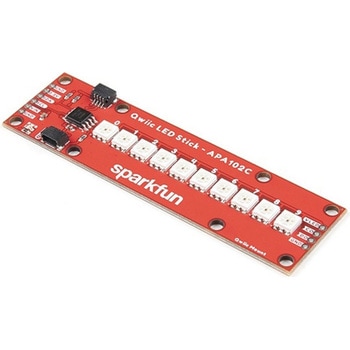 SparkFun Qwiic LED Stick - APA102CSPARKFUN
¥3,500税込¥3,850
1個
33日以内出荷
DescriptionThe SparkFun Qwiic LED Stick features ten addressable APA102 LEDs, making it easy to add full color LED control using I2C. Write to individual LEDs to display a count in binary, or write to the whole strip for cool lighting effects. You can even add more LEDs to the end if you need to. We've written an Arduino library and Python package that take care of the I2C and communication to the LEDs so all you have to do is decide what color each LED should be.The LED Stick has a default I2C address of 0x23 but can be changed with a simple command, allowing you to control up to 100 LEDs(10 Qwiic LED Sticks)on a single bus! The address can also be changed to 0x22 by closing the solder jumper on the back of the board.This board is one of our many Qwiic compatible boards! Simply plug and go. No soldering, no figuring out which is SDA or SCL, and no voltage regulation or translation required!Warning:Using a lot of LEDs can draw a lot of current. Make sure to consider the power limits of your setup. If you expect your LED chain to draw more than 600mA of current, connect your external supply directly to VLED. Closing the jumper from VLED to VCC will add a 4.7uF decoupling capacitor.The SparkFun Qwiic Connect System is an ecosystem of I2C sensors, actuators, shields and cables that make prototyping faster and less prone to error. All Qwiic-enabled boards use a common 1mm pitch, 4-pin JST connector. This reduces the amount of required PCB space, and polarized connections mean you can't hook it up wrong.Get Started with the Qwiic LED Stick GuideFeatures10x APA102C addressable LEDs driven by an ATTiny85Default I2C Address:0x23(Adjustable to 0x22 via Jumper)2x Qwiic Connectors
アズワン品番67-0421-83
 SparkFun Qwiic Alphanumeric Display - WhiteSPARKFUN
¥2,998税込¥3,298
1個
33日以内出荷
DescriptionWe are quite familiar with seven-segment displays. We see them on our alarm clocks, ovens, and microwaves. By adding more segments to each digit you can display more than just numbers! Introducing the brand new SparkFun Qwiic Alphanumeric Display. These white fourteen-segment digits allow you display all sorts of numbers, characters, and symbols. With Qwiic, simply plug it in and go. No soldering, no figuring out which is SDA or SCL, and no voltage regulation or translation required!The SparkFun Alphanumeric Display Arduino library makes printing strings to the display as easy as calling the print()function. With this library, you'll be able to send I2C commands to the VK16K33 LED driver chip to light up segments(including the decimal point or colon)and even scroll your string across the display. You can download the library through the Arduino library manager by searching 'SparkFun Alphanumeric Display' or you can get the GitHub repo as a .zip file and install the library from there.The VK16K33 also supports I2C address configuration. Simply close a combination of the address jumpers on the back and you can communicate with up to four displays on the same bus. Our slim board design also features detachable stand off holes, vertical Qwiic connectors, and internal mounting holes.The SparkFun Qwiic Connect System is an ecosystem of I2C sensors, actuators, shields and cables that make prototyping faster and less prone to error. All Qwiic-enabled boards use a common 1mm pitch, 4-pin JST connector. This reduces the amount of required PCB space, and polarized connections mean you can't hook it up wrong.Get Started with the Qwiic Alphanumeric Display Hookup GuideFeaturesWhite displayOperating Voltage:3.3VIntegrated RC oscillatorMaximum display segment numbers:128 patterns13×3 matrix key scan circuit16-step dimming circuitI2C Addresses:0x70(0x71, 0x72, 0x73)2x Qwiic connectors2x Wall Mounting Points
アズワン品番67-0421-87
 SparkFun Spectral Sensor Breakout - AS7263 NIR QwiicSPARKFUN
¥9,998税込¥10,998
1個
欠品中
DescriptionThe SparkFun AS7263 Near Infrared(NIR)Spectral Sensor Breakout brings spectroscopy to the palm of your hand, making it easier than ever to measure and characterize how different materials absorb and reflect different wavelengths of light. The AS7263 Breakout is unique in its ability to communicate by both an I2C interface and serial interface using AT commands. Hookup is easy, thanks to the Qwiic connectors attached to the board --- simply plug one end of the Qwiic cable into the breakout and the other into one of the Qwiic shields, then stack the board on a development board. You'll be ready to upload a sketch to start taking spectroscopy measurements in no time.The AS7263 spectrometer detects wavelengths in the visible range at 610, 680, 730, 760, 810 and 860nm of light, each with 20nm of full-width half-max detection. The board also has multiple ways for you to illuminate objects that you will try to measure for a more accurate spectroscopy reading. There is an onboard LED that has been picked out specifically for this task, as well as two pins to solder your own LED into.Note:The I2C address of the AS7263 is 0x49 and is hardware defined. A multiplexer/Mux is required to communicate to multiple AS7263 sensors on a single bus. If you need to use more than one AS7263 sensor consider using the Qwiic Mux Breakout.The SparkFun Qwiic Connect System is an ecosystem of I2C sensors, actuators, shields and cables that make prototyping faster and less prone to error. All Qwiic-enabled boards use a common 1mm pitch, 4-pin JST connector. This reduces the amount of required PCB space, and polarized connections mean you can't hook it up wrong.Get Started with the SparkFun AS726X Spectral Sensor Breakout GuideFeatures6 near-IR channels:610nm, 680nm, 730nm, 760nm, 810nm and 860nm, each with 20nm FWHMNIR filter set realized by silicon interference filters16-bit ADC with digital accessProgrammable LED drivers2.7V to 3.6V with I2C interface2x Qwiic connectors
アズワン品番67-0426-70
 SparkFun Real Time Clock Module - RV-8803 QwiicSPARKFUN
¥5,798税込¥6,378
1個
33日以内出荷
DescriptionThe SparkFun RV-8803 Real Time Clock Module is a Qwiic-enabled breakout board for the RV-8803 RTC. The RV-8803 boasts some impressive features including a temperature compensated crystal providing extremely precise time-keeping, low power consumption, and time stamp event input along with a user-programmable timing offset value. The RV-8803 also has an improved I2C interface compared to the RV-1805 RTC that removes the need to sequence commands/writes to the device. Best of all, the temperature compensation comes factory calibrated. Utilizing our handy Qwiic system so no soldering is required to connect it to the rest of your system. However, we still have broken out 0.1"-spaced pins in case you prefer to use a breadboard.Adding a real-time clock to your project is the perfect way to get more accurate data; timing or otherwise. Using the Qwiic connector makes for a fast, solid way to incorporate this into your project. The RTC module has counters for hundredths of seconds, seconds, minutes, hours, date, month, year and weekday with a number of alarm and interrupt settings available as well. Plus the large operating temperature range(-40 to +105℃)and temperature compensated crystal makes for a good addition for field applications or harsh environments.The SparkFun Qwiic Connect System is an ecosystem of I2C sensors, actuators, shields and cables that make prototyping faster and less prone to error. All Qwiic-enabled boards use a common 1mm pitch, 4-pin JST connector. This reduces the amount of required PCB space, and polarized connections mean you can't hook it up wrong.Get Started with the SparkFun RV-8803 Real Time Clock Module GuideFeaturesFactory Calibrated Temperature CompensationHigh Time Accuracy±1.5 ppm 0 to +50℃±3.0 ppm -40 to +85℃±7.0 ppm +85 to +105℃1.5V to 5.5V Operating Voltage Range240nA @ 3.3v Low-Power ConsumptionI2C Address:0x32Periodic Countdown Timer Interrupt functionPeriodic Time Update Interrupt function(seconds, minutes)Alarm Interrupts for weekday or date, hour and minute settingsExternal Event Input with Interrupt and Time Stamp functionProgrammable Clock Output pin for peripheral devices.Operating temperature range:-40 to +105℃2x Qwiic Connectors
アズワン品番67-0420-10