カテゴリ
- 学童・教育用品(16)
絞り込み
ブランド
- SPARKFUN
- X.A.M(489)
- SUS(エスユーエス)(266)
- ニッサン(35)
- 日本精器(30)
- MAD MAX(マッドマックス)(30)
- SANEI(旧:三栄水栓製作所)(22)
- プロトブレンボ(18)
- TP-LINK(14)
- LAMP(スガツネ工業)(13)
- メディアカバーマーケット(11)
- HARWIN(10)
- オカムラ(岡村製作所)(9)
- CREE(8)
- Seeed Studio(8)
- BEAMS(ビームス)(7)
- 長谷川工業(6)
- ハゼット(6)
- ALPINE(6)
- ブランドをもっと見る
「xam」の検索結果
特価
 RF Link Transmitter - 315MHzSPARKFUN
¥1,698税込¥1,868
1個
33日以内出荷
DescriptionThese wireless transmitters work with our 315MHz receivers. They can easily fit into a breadboard and work well with microcontrollers to create a very simple wireless data link. Since these are only transmitters, they will only work communicating data one-way, you would need two pairs(of different frequencies)to act as a transmitter/receiver pair.Note:These modules are indiscriminate and will receive a fair amount of noise. Both the transmitter and receiver work at common frequencies and don't have IDs. Therefore, a method of filtering this noise and pairing transmitter and receiver will be necessary. The example code below shows such an example for basic operation. Please refer to the example code and links below for ways to accomplish a robust wireless data link.Features315MHz500ft range(given perfect conditions)4800bps data rate5V supply voltage
アズワン品番67-0430-46
 LilyPad Sewable Electronics Kit GuidebookSPARKFUN
¥2,098税込¥2,308
1個
33日以内出荷
DescriptionThe full-color LilyPad Sewable Electronics Kit Guidebook contains step-by-step instructions for creating four interactive projects from the materials contained in the kit. Examples and circuits are provided and explained. The manual also includes a glossary and troubleshooting tips. Once you make your way through all of the projects, you will have a much better grasp on e-textiles!Note:This is just the manual for the LilyPad Sewable Electronics Kit. The kit itself or the individual parts used in this book will need to be purchased separately.ExamplesProject 1:Glowing PinProject 2:Illuminated MaskProject 3:Light-Up PlushProject 4:Night-Light Pennant
アズワン品番67-0420-18
 RF Link Receiver - 4800bps 315MHzSPARKFUN
¥1,998税込¥2,198
1個
33日以内出荷
DescriptionThese wireless receivers work with our 315MHz transmitters. They can easily fit into a breadboard and work well with microcontrollers to create a very simple wireless data link. Since these are only receivers, they will only work communicating data one-way, you would need two pairs(of different frequencies)to act as a transmitter/receiver pair.Note:These modules are indiscriminate and will receive a fair amount of noise. Both the transmitter and receiver work at common frequencies and don't have IDs. Therefore, a method of filtering this noise and pairing transmitter and receiver will be necessary. The example code below shows such an example for basic operation. Please refer to the example code and links below for ways to accomplish a robust wireless data link.Note:These receivers are almost identical to the RF link 434MHz receiver. SparkFun does everything in our power to make sure you receive the product you requested. However, if you are concerned you may have received the incorrect product you can verify which version receiver this is by running a simple test circuit.Features315 MHz500ft range(given perfect conditions)4800bps data rate5V supply voltage
アズワン品番67-0430-44
 LED RGB Strip - Addressable, Sealed, 1m APA104SPARKFUN
¥9,998税込¥10,998
1個
欠品中
DescriptionGone are the days that you have to worry about silicone weather proofing splitting and breaking on you! These are sealed addressable 1 meter long 5V RGB LED strips that come packed with 60 APA104s per meter. Each of these strips are enclosed by a flexible silicon jacket with an IP65 waterproof rating to protect your precious APA104 LEDs. You will be able to control each RGB LED individually giving you the ability to create cool lighting effects for your car, fish tank, or perhaps under cabinet lighting in your kitchen! These LED strips are compatible with similar WS2812 and SK6812 addressable LED's.Note:These come in 1m segments on a reel. They are preterminated with 0.1" spaced 3-pin connectors as well as a 2 wire power connector, as shown in the pictures.FeaturesFlexible LED strip with external control for each LED pixelHigh brightness, full-color and fully addressable(cascade, chasing and scanning)Maximum length of 5 metersExample uses include architectural, landscape, and decorative lighting
アズワン品番67-0421-40
 SparkFun Soil Moisture Sensor with Screw TerminalsSPARKFUN
¥2,198税込¥2,418
1個
33日以内出荷
DescriptionThe SparkFun Soil Moisture Sensor is a simple breakout for measuring the moisture in soil and similar materials. The soil moisture sensor is pretty straightforward to use. The two large, exposed pads function as probes for the sensor, together acting as a variable resistor. The more water that is in the soil means the better the conductivity between the pads will be, resulting in a lower resistance and a higher SIG out. This version of the Soil Moisture Sensor includes a 3-pin screw pin terminal pre-soldered to the board for easy wiring and setup.To get the SparkFun Soil Moisture Sensor functioning, all you will need is to connect the VCC and GND pins to your Arduino-based device(or compatible development board). You will receive a SIG out, which will depend on the amount of water in the soil. One commonly known issue with soil moisture senors is their short lifespan when exposed to a moist environment. To combat this, we've had the PCB coated in gold finishing(ENIG, or Electroless Nickel Immersion Gold).Note:Check the Hookup Guide below for assembly and weatherproofing instructions, as well as a simple example project that you can put together yourself!Get Started with the Soil Moisture Sensor Guide
アズワン品番67-0426-56
 SparkFun Inventor's Kit for Arduino Uno - v4.1SPARKFUN
¥34,980税込¥38,478
1個
33日以内出荷
DescriptionThe SparkFun Inventor's Kit(SIK)for Arduino Uno is a great way to get started with programming and hardware interaction with the Arduino programming language. The SIK includes everything you need to complete five overarching projects consisting of 16 interconnected circuits that teach everything from blinking an LED to reading sensors. The culminating project is your very own autonomous robot! No previous programming or electronics experience is required to use this kit.The online guide contains step-by-step instructions with circuit diagrams and hookup tables for building each project and circuit with the included parts. Full example code is provided, new concepts and components are explained at point of use, and troubleshooting tips offer assistance if something goes wrong.The kit does not require any soldering and is recommended for beginners ages 10 and up who are looking for an Arduino starter kit. For SIK version 4.1 we took an entirely different approach to teaching embedded electronics. In previous versions of the SIK, each circuit focused on introducing a new piece of technology. With SIK v4.1, components are introduced in the context of the circuit you are building, and each circuit builds upon the last, leading up to a project that incorporates all of the components and concepts introduced throughout the guide. With new parts and a completely new strategy, even if you've used the SIK before, you're in for a brand-new experience!This version of the SIK replaces the SparkFun RedBoard Qwiic with the Arduino Uno(SMD version)and comes without the SIK guidebook and carrying case. With these components being swapped and removed, we were able to reduce the overall size and weight of the kit, making shipping cheaper and easier for anyone ordering internationally.Note:As stated above, this SIK does NOT include a carrying case or print guidebook.Get Started With the SparkFun Inventor's Kit v4.1 Experiment GuideExamplesProject 1:LightCircuit 1A:Blinking an LEDCircuit 1B:PotentiometerCircuit 1C:PhotoresistorCircuit 1D:RGB Night-LightProject 2:SoundCircuit 2A:BuzzerCircuit 2B:Digital TrumpetCircuit 2C:"Simon Says" GameProject 3:MotionCircuit 3A:Servo MotorsCircuit 3B:Distance SensorCircuit 3C:Motion AlarmProject 4:DisplayCircuit 4A:LCD "Hello, World!"Circuit 4B:Temperature SensorCircuit 4C:"DIY Who Am I?" GameProject 5:RobotCircuit 5A:Motor BasicsCircuit 5B:Remote-Controlled RobotCircuit 5C:Autonomous Robot
アズワン品番67-0424-34
 SparkFun Inventor's Kit Bridge Pack for micro:bitSPARKFUN
¥15,980税込¥17,578
1個
33日以内出荷
DescriptionDo you own micro:bit or micro:bit Go Bundle and want to expand your skills with the new microcontroller? You are in luck! The SparkFun Inventor's Kit Bridge Pack for micro:bit was designed to provide you with an easy way to transform your m:b into full fledged learning kit! Each Bridge Pack includes all of the parts found in the SIK for micro:bit that aren't included with the Go Bundle. With the SIK Bridge Pack for micro:bit you will be able to complete circuits that will teach you how to read sensors, move motors, build Bluetooth(R)devices and more.The micro:bit is pocket-sized computer that lets you get creative with digital technology. Between the micro:bit and our shield-like bit boards you can do almost anything while coding, customizing and controlling your micro:bit from almost anywhere! You can use your micro:bit for all sorts of unique creations, from robots to musical instruments and more. At half the size of credit card, this versatile board has vast potential!Note:The Bridge Pack is NOT full SparkFun Inventor's Kit and only includes the parts to complement micro:bit Go Bundle or standalone board. That also means that this kit doesnotinclude micro:bit, which will need to be purchased separately.Get started with the micro:bit SIK Experiment GuideExamplesCircuit 0:Hello, micro:bit!Circuit 1:Blinking an LEDCircuit 2:Reading PotentiometerCircuit 3:Reading PhotoresistorCircuit 4:Driving an RGB LEDCircuit 5:Reading an SPDT SwitchCircuit 6:Reading Button PressCircuit 7:Reading the Temperature SensorCircuit 8:Using Servo MotorCircuit 9:Using BuzzerCircuit 10:Using the AccelerometerCircuit 11:Using the Compass
アズワン品番67-0424-21
 SparkFun Inventor's Kit for micro:bit v2 Lab PackSPARKFUN
¥159,800税込¥175,780
1個
33日以内出荷
DescriptionThe SparkFun Inventor's Kit for micro:bit v2 Lab Pack includes 10 complete micro:bit v2 Inventor's Kits, an SIK Refill Pack and 25 AAA-sized batteries to get your students started in the world of electronics. The SIKs inside the Lab Pack have everything you need, including micro:bit v2s, connector breakouts, breadboards and all the cables and accessories to hook up all the projects listed in our online Experiment Guide.The kit does not require any soldering and is recommended for all users, from beginners to engineering students. We have provided a complete Experiment Guide in the Documents tab for you to check out now! If you are new to teaching electronics or have taught with the original SparkFun Inventor's Kit and are looking for something new, the SIK for micro:bit v2 is the perfect kit for you!SparkFun packages everything educators need to get started with this platform in a variety of classroom and makerspace settings with diverse student populations. The hardware boards, cables and extra parts come pre-packaged, and our online support materials --- including an online Experiment Guide(to be updated)--- help you bring the power of the open source community to your classroom. Examples and curriculum materials are available from SparkFun and Arduino, as well as from other educators involved in this growing maker movement.The micro:bit is a pocket-sized computer that lets you get creative with digital technology. Between the micro:bit and our shield-like bit boards you can do almost anything while coding, customizing and controlling your micro:bit from almost anywhere! You can use your micro:bit for all sorts of unique creations, from robots to musical instruments and more. At half the size of a credit card, this versatile board has vast potential!
アズワン品番67-0424-93
 SparkFun OpenScaleSPARKFUN
¥11,980税込¥13,178
1個
33日以内出荷
DescriptionThe SparkFun OpenScale is a simple-to-use, open source solution for measuring weight and temperature. It has the ability to read multiple types of load cells and offers a simple-to-use serial menu to configure calibration value, sample rate, time stamp and units of precision.Simply attach a four-wire or five-wire load cell of any capacity, plug the OpenScale into a USB port, open a terminal window at 9,600bps, and you'll immediately see mass readings. The SparkFun OpenScale will enable you to turn a load cell or four load sensors in a Wheatstone bridge configuration into the DIY weigh scale for your application.The OpenScale was designed for projects and applications where the load was static(like the beehive in front of SparkFun HQ)or where constant readings are needed without user intervention(for example, on a conveyor belt system). A load cell with an equipped OpenScale can remain in place for months without needing user interaction!On board the SparkFun OpenScale is the ATmega328P microcontroller, for addressing your communications needs and transferring your data to a serial terminal or to a data logger such as the OpenLog, an FT231 with mini USB, for USB to serial connection; the HX711, a 24-bit ADC for weigh scales; and the TMP102, for recording the ambient temperature of your system. The OpenScale communicates at a TTL level of 9,600bps 8-N-1 by default and possesses a baud rate configurable from 1,200bps to 1,000,000bps.Get Started with the OpenScale GuideFeaturesOperating Voltage:5VOperating Ampage:80-100mAPower Cycling above 500msSelectable 10SPS or 80SPS Output Data RateLocal External Temperature SensorsFixed Adjustable Gain
アズワン品番67-0426-48
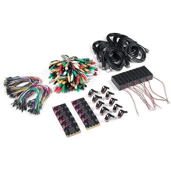
 LilyPad Sewable Electronics KitSPARKFUN
¥31,980税込¥35,178
1個
33日以内出荷
DescriptionThe LilyPad Sewable Electronics Kit lets you explore the wonderful world of electronic sewing(e-sewing)and e-textiles through a series of introductory projects using the LilyPad system. You'll learn how to sew basic circuits to light up LEDs, control them with buttons and switches and even experiment with a pre-programmed LilyMini circuit that reacts to ambient light levels. In addition to LilyPad LEDs and battery holders, the kit comes with two LilyPad ProtoSnap boards that let you explore the circuit before you sew the pieces into a project.The full-color LilyPad Sewable Electronics Kit Guide(included)contains step-by-step instructions for using LilyPad pieces to create four complete sewable circuit projects with conductive thread. Easy-to-follow diagrams and troubleshooting tips make this a great introductory resource for crafters and creatives.LilyPad is a wearable technology developed by Dr. Leah Buechley and cooperatively designed by Dr. Buechley and SparkFun. Each LilyPad component was creatively constructed with large sew tabs to allow for stitching into clothing. Various input, output, power and sensor boards are available. They're even washable!Note:A portion of this sale is given back to Dr. Buechley for continued development and education in e-textiles.Note:Due to the requirements of shipping the batteries in this kit, orders may take longer to process and therefore do not qualify for same-day shipping. Additionally, these batteries can not be shipped via Ground or Economy methods to Alaska or Hawaii. Sorry for any inconvenience this may cause.ExamplesSewable Electronics Projects:Project 1:Glowing PinProject 2:Illuminated MaskProject 3:Light-Up PlushProject 4:Night-Light Pennant
アズワン品番67-0424-05
 SparkFun Inventor's Kit for micro:bit v2SPARKFUN
¥17,980税込¥19,778
1個
33日以内出荷
DescriptionThe SparkFun Inventor's Kit(SIK)for micro:bit v2 is a great way to get creative, connected and coding with the micro:bit. The SIK for micro:bit v2 provides not only the micro:bit v2 board but everything you need to hook up and experiment with multiple electronic circuits! With the SIK for micro:bit v2 you will be able to complete circuits that will teach you how to read sensors, move motors, build Bluetooth(R)devices and more.The SparkFun Inventor's Kit for micro:bit is the latest and greatest in single-board computer kits. Surrounding the micro:bit v2 SIK is one core philosophy --- that anyone can(and should)experiment with cutting-edge electronics in a fun and playful way without breaking the bank.The kit does not require any soldering and is recommended for all users, from beginners to engineers. We have provided a complete Experiment Guide in the Documents tab for you to check out now! If you have ever been interested in learning about electronics, or if you have used the original SparkFun Inventor's Kit and are looking for something new, the SIK for micro:bit is the perfect kit for you!The micro:bit is a pocket-sized computer that lets you get creative with digital technology. Between the micro:bit and our shield-like bit boards you can do almost anything while coding, customizing and controlling your micro:bit from almost anywhere! You can use your micro:bit for all sorts of unique creations, from robots to musical instruments and more. At half the size of a credit card, this versatile board has vast potential!ExamplesCircuit 0:Hello, micro:bit!Circuit 1:Blinking an LEDCircuit 2:Reading a PotentiometerCircuit 3:Reading a PhotoresistorCircuit 4:Driving an RGB LEDCircuit 5:Reading an SPDT SwitchCircuit 6:Reading a Button PressCircuit 7:Reading the Temperature SensorCircuit 8:Using a Servo MotorCircuit 9:Using a BuzzerCircuit 10:Using the AccelerometerCircuit 11:Using the Compass
アズワン品番67-0424-61
 SparkFun Qwiic Button - Green LEDSPARKFUN
¥1,698税込¥1,868
1個
33日以内出荷
DescriptionButtons are an easy and tactile way to interface with your project, but why would you want to deal with debouncing, polling, and wiring up pull-up resistors? The Qwiic Button with built-in green LED simplifies all of those nasty worries away into an easy to use I2C device! Utilizing our Qwiic Connect System, using the button is as simple as connecting cable and loading up some pre-written code!If you need multiple buttons for your project, fear not! Each button has configurable I2C address, so you can daisy-chain multiple buttons over Qwiic and still address each one individually. We've got an example in our Arduino library that provides super-easy way to configure your Qwiic Button to whatever I2C address you desire. You can download the library through the Arduino library manager by searching 'SparkFun Qwiic Button' or you can get the GitHub repo as .zip file and install the library from there.In addition to handling blinking and debouncing, the Qwiic Button has configurable interrupts that can be configured to activate upon button press or click. We've also taken the liberty of implementing FIFO queue onboard the Qwiic Button where it keeps an internal record of when the button was pressed. This means that code on your microcontroller need not waste valuable processing time checking the status of the button but instead can run small function whenever the button is pressed or clicked! For more information on interrupts check out our guide here!The SparkFun Qwiic Connect System is an ecosystem of I2C sensors, actuators, shields and cables that make prototyping faster and less prone to error. All Qwiic-enabled boards use common 1mm pitch, 4-pin JST connector. This reduces the amount of required PCB space, and polarized connections mean you can't hook it up wrong.Get Started with the SparkFun Qwiic Button GuideFeatures12mm Green LED Button rated for 50mABuilt in LED can be configured for your desired level of blinkiness!Each button has configurable I2C addressConfigurable interrupts check out our guide here!FIFO queueDon't like the color green? Check out the SparkFun Qwiic Button Breakout and add another colored button!Red LED Tactile ButtonBlue LED Tactile ButtonGreen LED Tactile ButtonWhite LED Tactile Button
アズワン品番67-0420-14
 Alchitry Cu FPGA Development Board Lattice iCE40 HXSPARKFUN
¥15,980税込¥17,578
1個
33日以内出荷
DescriptionIf you are not needing a lot of power to start your FPGA adventure, or are looking for a more economical option, the Alchitry Cu FPGA Development Board might be the perfect option for you! The Alchitry Cu is a "lighter" FPGA version than the Alchitry Au but still offers something completely unique. FPGAs, or Field-Programmable Gate Arrays, are an advanced development board type for engineers and hobbyists alike to experience the next step in programming with electronics. The Cu truly exemplifies the trend of more affordable and increasingly powerful FPGA boards arriving each year. This board is a fantastic starting point into the world of FPGAs and the heart of your next project. Finally, now that this board is built by SparkFun, we added a Qwiic connector for easy I2C integration!The Alchitry Cu uses the Lattice iCE40 HX FPGA with 7680 logic cells and is supported by the open source tool chain Project IceStorm. The Cu possesses 79 IO pins with eight general purpose LEDs; a 100MHz on-board clock that can be manipulated internally by the FPGA; a USB-C connector to configure and power the board; and a USB to serial interface for data transfer.By adding stackable expansion boards similar to shields or HATs called "Elements," the Alchitry Cu is able to expand its own hardware capabilities by adding prototyping spaces, buttons, LEDs, and more!The SparkFun Qwiic Connect System is an ecosystem of I2C sensors, actuators, shields and cables that make prototyping faster and less prone to error. All Qwiic-enabled boards use a common 1mm pitch, 4-pin JST connector. This reduces the amount of required PCB space, and polarized connections mean you can't hook it up wrong.Get Started with our Learning FPGA TutorialsFeaturesLattice iCE40-HX8K FPGA - 7680 logic elements79 IO pins(3.3V logic level)USB-C to configure and power the boardEight general purpose LEDsOne button(typically used as a reset)100MHz on-board clock(can be multiplied internally by the FPGA)Powered with 5V through USB-C port, 0.1" holes, or headersUSB to serial interface for data transfer(up to 12Mbaud)Qwiic ConnectorDimensions of 65mm×45mmExamplesFirst FPGA Project - Getting Fancy with PWMExternal IO and Metastability
アズワン品番67-0423-08
 SparkFun Educator Lab Pack for micro:bit v2SPARKFUN
¥109,800税込¥120,780
1個
33日以内出荷
DescriptionThe micro:bit v2 Educator's Lab Pack includes 10 micro:bit v2 boards and everything you need to get you started with the new learning platform. The Lab Pack has everything you need, including micro:bits, cables, battery packs and a few parts to experiment with. This package provides an easy way to introduce your students to the micro:bit without any difficulty or parts hunting.SparkFun packages everything educators need to get started with the micro:bit in a variety of classroom settings and learning environments. The hardware boards, cables and extra parts come pre-packaged. Examples and curriculum materials are available from SparkFun and micro:bit, as well as from other educators involved in this growing maker education movement.Lab Packs are your classroom entry point. By combining our kits, popular boards and other educational tools with support materials(to be updated), SparkFun brings all the power of the open source community to the classroom. We've also updated the battery pack to be closer to what is in other micro:bit kits. It now requires 2xAAA batteries.The micro:bit is a pocket-sized computer that lets you get creative with digital technology. Between the micro:bit and our shield-like bit boards you can do almost anything while coding, customizing and controlling your micro:bit from almost anywhere! You can use your micro:bit for all sorts of unique creations, from robots to musical instruments and more. At half the size of a credit card, this versatile board has vast potential!FeaturesMicro:bit 2.0:64 MHz Arm Cortex-M4 with FPU512KB Flash128KB RAM5x5 Red LED ArrayTwo Programmable Buttons, one touch sensitive logoMEMS microphone and LED indicatorOnboard Light, Compass, Accelerometer, Temp Sensors and Speaker2.4 Ghz Micro:bit Radio/BLE 5.0 Smart Antenna25-pin Edge Connector4 dedicated GPIO, PWM, i2c, SPI, and ext. powerThree Digital/Analog Input/Output RingsTwo Power Rings --- 3V and GNDDedcated I2C bus for peripheralsMicroUSB Connector(5V)JST-PH Battery Connector(NotJST-XH)(3V)Power/reset Button with Status LED200 mA available for accessoriesProgram with C++, MakeCode, Python, Scratch
アズワン品番67-0424-92
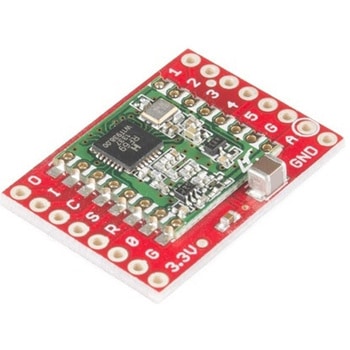 SparkFun RFM69 Breakout 434MHzSPARKFUN
¥4,398税込¥4,838
1個
33日以内出荷
DescriptionThis is the SparkFun RFM69 Breakout, a small piece of tech that breaks out all the pins available on the RFM69HCW module as well as making the transceiver easy to use. The RFM69HCW is an inexpensive and versatile radio module that operates in the unlicensed ISM(Industry, Science and Medicine)radio band. It's perfect for building inexpensive short-range wireless networks of sensors and actuators for home automation, citizen science and more.This RFM69HCW operates on the 434MHz frequency and is capable of transmitting at up to 100mW and up to 300kbps, but you can change both of those values to fit your application. For example, you can maximize range by increasing the transmit power and reducing the data rate, or you can reduce both for short-range sensor networks that sip battery power. At full power and with simple wire antennas, we can get messages from one side of a large office building to the other through numerous internal walls. In open air you can reach 500 meters or more. With more complex antennas and modulation schemes, similar parts have successfully transmitted from space to the ground(by very smart amateur radio enthusiasts; your mileage may vary)!The RFM69HCW uses an SPI(Serial Peripheral Interface)to communicate with a host microcontroller, and several good Arduino libraries are available. It supports up to 256 networks of 255 nodes per network, features AES encryption to keep your data private, and transmits data packets up to 66 bytes long.SparkFun sells two versions of the RFM69HCW:a 915MHz version and this 434MHz version. Although the ISM band is license-free, the band itself is different in different areas. Very roughly, 915MHz is for use in the Americas, and the 434MHz version is for use in Europe, Asia and Africa. Check your local regulations for other areas.Get Started with the RFM69HCW Hookup GuideFeaturesTransmit power:-18dBm(0.016mW)to +20dBm(100mW)in 1dBm stepsReceive sensitivity:down to -120dBm at 1.2kbpsModulation types:FSK GFSK MSK GMSK OOKBit rates(FSK):1.2kbps to 300kbpsVoltage range:1.8V to 3.6VCurrent consumption:0.1uA sleep, 1.25mA standby, 16mA receive, 130mA transmit(max)Encryption:AES 128-bit(optional)Packet buffer(FIFO):66 bytes0.8"×1.1"
アズワン品番67-0429-33
 SparkFun Cryptographic Co-Processor Breakout - ATECC608A QwiicSPARKFUN
¥1,498税込¥1,648
1個
33日以内出荷
DescriptionProduct Restrictions:To access certain features of the ATECC608A, users will need to contact Microchip and sign an NDA contract to obtain the complete datasheet. Due to the required NDA - technical support, an Arduino library, and hookup guide are not provided for users on this product.The SparkFun ATECC608A Cryptographic Co-processor Breakout allows you to add strong security to your IoT node, edge device, or embedded system. This includesasymmetricauthentication,symmetricAES-128 encryption/decryption, and much more. As stated above, the ATECC608A has limited Arduino support and the complete datasheet is under NDA with Microchip.This breakout board includes two Qwiic ports for plug and play functionality. Utilizing our handy Qwiic system, no soldering is required to connect it to the rest of your system. However, we still have broken out 0.1"-spaced pins in case you prefer to use a breadboard. The ATECC608A chip is capable of many cryptographic processes, including, but not limited to:Creating and securely storing unique asymmetric key pairs based on Elliptic Curve Cryptography(FIPS186-3).AES-128:Encrypt/Decrypt, Galois Field Multiply for GCMCreating and verifying 64-byte digital signatures(from 32-bytes of message data).Creating a shared secret key on a public channel via Elliptic Curve Diffie-Hellman Algorithm.SHA-256 HMAC Hash including off-chip context save/restoreInternal high quality FIPS random number generator.Embedded in the chip is a 10Kb EEPROM array that can be used for storing keys, certificates, data, consumption logging, and security configurations. Access to the sections of memory can then be restricted and the configuration locked to prevent changes. Each ATECC608A Breakout ships with a guaranteed unique 72-bit serial number and includes several security features to prevent physical attacks on the device itself, or logical attacks on the data transmitted between the device.A summary datasheet for the ATECC608A is available here. The full datasheet is under NDA with Microchip. You will need to contact them for access to the entire datasheet. Meanwhile, the ArduinoATECCX08 Library currently only supports the ATECC608A with SAMD21 Arduino boards.We do have much more support for the ATECC508A version of this chip. Please check out our ATECC508A Hookup Guide and Arduino Library(which includes six examples). This will get you familiar with the basics of elliptic curve cryptography and signing/verifying data with the ATECC508A version of the chip.Note:The I2C address of the ATECC608A is 0x60 and is software-configurable to any address. A multiplexer/Mux is required to communicate to multiple ATECC608A sensors at the default address when on a single bus. If you need to use more than one ATECC608A sensor at the default address, consider using the Qwiic Mux Breakout.Note:The ATECC608A can be only configured once before it isPERMANENTLYlocked. It is advisable that users purchase multiple boards in order to use other configurations and explore the advanced functions of the ATECC608A.Additionally, this boardIScapable of encrypting and decrypting data. However, to access these additional features, you will need to contact Microchip and sign an NDA contract to obtain the complete datasheet.It is recommended that an SparkFun RedBoard Turbo - SAMD21 Development Board is used with this product due to the buffer size required on the I2C bus.The SparkFun Qwiic Connect System is an ecosystem of I2C sensors, actuators, shields and cables that make prototyping faster and less prone to error. All Qwiic-enabled boards use a common 1mm pitch, 4-pin JST connector. This reduces the amount of required PCB space, and polarized connections mean you can't hook it up wrong.FeaturesOperating Voltage:2.0V-5.5V(Default on Qwiic System:3.3V)Active Current Draw(for ATECC608A):16 mASleep Current(for ATECC608A):<150 nAGuaranteed Unique 72-bit Serial Number10 Kb EEPROM Memory for Keys, Certificates, and DataStorage for up to 16 Keys256-bit Key LengthInternal High-Quality FIPS Random Number Generator(RNG)Configurable I2C Address(7-bit):0x60(Default)
アズワン品番67-0423-59