カテゴリ
- すべてのカテゴリ
- オフィスサプライ
- 学童・教育用品
- 理科/技術/科学工作(20)
- 学童・教育用品
- オフィスサプライ
絞り込み

 Qwiic JST-SH Micro SMTテストフック付 4ピンケーブルAdafruit
¥999税込¥1,099
1個
欠品中
仕様●タイプ:オプション品●カテゴリ:-●機能:-●使用IC/部品:-●プラットフォーム:Qwiic●タイプ:オプション品アズワン品番68-2095-47
 Qwiic JST Connector - SMD 4-Pin VerticalSPARKFUN
¥259税込¥285
1個
33日以内出荷
DescriptionHere is a tiny 4-pin Qwiic 1mm JST connector. This connector mounts to allow you to connect your cable vertically, great for tight spaces. This connector is used on all of our Qwiic-based boards and can be used to create your own I2C-based
アズワン品番67-0425-88
 JST SH Vertical 6-Pin Connector - SMDSPARKFUN
¥719税込¥791
1個
33日以内出荷
仕様●シリーズ名:(汎用品)●種別:GPSアズワン品番67-0453-87
 Qwiic JST Connector - SMD 4-pin HorizontalSPARKFUN
¥209税込¥230
1個
33日以内出荷
DescriptionHere is a tiny 4-pin Qwiic 1mm JST connector. This connector is used on all of our Qwiic-based boards and can be used to create your own I2C-based device compatible with the Qwiic system. Additionally, this connector will mate with all of
アズワン品番67-0425-41
 JST Right-Angle Connector - SMD 2-Pin BlackSPARKFUN
¥329税込¥362
1個
33日以内出荷
DescriptionThis is a two pin, compact surface mount JST connector. We really like the solid locking feeling and high current rating on these small connectors. We use these all the time as battery connectors.
アズワン品番67-0425-09
 PureThermal Mini Pro JST-SR with FLIR Lepton 3.5SPARKFUN
¥129,800税込¥142,780
1個
38日以内出荷
DescriptionThe new PureThermal Mini Pro JST-SR with Thermal by FLIR is a hackable thermal camera for the FLIR Lepton thermal imaging camera core. Just like its PureThermal 2 predecessor, it ships pre-configured to operate as a plug-and-play UVC 1.0 USB thermal webcam that will work with standard webcam and video apps on all major platforms using a JST-SR to USB Cable, or your own custom cable. For developers, its reference firmware and viewer software are open source.It has multiple connection options such as solder straight to the board or a custom cable using the JST-SR port. The PTMini Pro also features four mounting holes, less complex circuitry, and perhaps best of all, USB DFU. This is a development kit ready to be embedded into a production system.Each board comes with a FLIR Lepton 3.5.The FLIR Lepton(R)is a radiometric-capable LWIR camera solution that is smaller than a dime, fits inside a smartphone, and is one tenth the cost of traditional IR cameras. Using focal plane arrays of either 160x120 or 80x60 active pixels, Lepton easily integrates into native mobile-devices and other electronics as an IR sensor or thermal imager. The radiometric Lepton captures accurate, calibrated, and noncontact temperature data in every pixel of each image.FeaturesPureThermal:Compatible with all production FLIR Leptons, including radiometric 2.5 and 3.5 cores9 Hz color video over usb using the USB UVC classSTM32F412 ARM microprocessor - execute on-board image processing without need for an external systemOpen source reference firmware:GroupGets PureThermal GithubWorks with GetThermal - our custom open source thermal video display software for macOS and Linux with radiometric supportDFU over USB using a JST-SR port to USB cable, or a modified USB cable and the through holes.Four mounting holesCompact form-factor ready to be embedded into production systemsFLIR Lepton 3.5:Thermal sensitivity:< 50 mK(0.050℃)Spectral Range:8 - 14 microns(nominal)Long Wave Infrared(LWIR)Resolution:160h×120v pixelsRadiometric Accuracy - High Gain Mode:Greater of +/- 5℃ or 5%(typical); Low Gain Mode:Greater of +/- 10℃ or 10%(typical)Scene Dynamic Range - High Gain Mode:-10° to +140℃; Low Gain Mode:-10° to +400℃(at room temperature), -10° to +450℃(typical)Pixel Size:12 micrometersFrame Rate:8.7 Hz(effective)Output Format:User-selectable 14-bit, 8-bit(AGC applied), or 24-bit RGB(AGC and colorization applied)Horizontal Field of View(HFOV):57°Lens Type:f/1.1Size(w×l×h):10.50×12.70×7.14 mmWeight:0.9 gramsPower Consumption:150 mW typical, 650 mW during shutter event, 5mW standbyOptimum Operating Temperature Range:-10℃ to + 80℃
アズワン品番67-0423-44
 Monk Makes Micro-bit用電源 SKU00074Monk Makes
¥1,698税込¥1,868
1個
6日以内出荷
一方の端に2.1mm DCバレルジャックソケットが付いており、3.3Vの安定化出力により、JSTバッテリコネクタを基板のもう一方の端からくるワイヤに接続してマイクロビットに電力を供給できる。
タイププロダクト:BBC マイクロビット用アドオンRoHS指令(10物質対応)対応
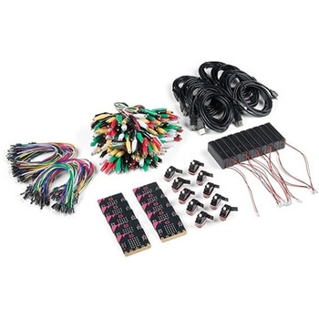 SparkFun Educator Lab Pack for micro:bit v2SPARKFUN
¥109,800税込¥120,780
1個
33日以内出荷
DescriptionThe micro:bit v2 Educator's Lab Pack includes 10 micro:bit v2 boards and everything you need to get you started with the new learning platform. The Lab Pack has everything you need, including micro:bits, cables, battery packs and a few parts to experiment with. This package provides an easy way to introduce your students to the micro:bit without any difficulty or parts hunting.SparkFun packages everything educators need to get started with the micro:bit in a variety of classroom settings and learning environments. The hardware boards, cables and extra parts come pre-packaged. Examples and curriculum materials are available from SparkFun and micro:bit, as well as from other educators involved in this growing maker education movement.Lab Packs are your classroom entry point. By combining our kits, popular boards and other educational tools with support materials(to be updated), SparkFun brings all the power of the open source community to the classroom. We've also updated the battery pack to be closer to what is in other micro:bit kits. It now requires 2xAAA batteries.The micro:bit is a pocket-sized computer that lets you get creative with digital technology. Between the micro:bit and our shield-like bit boards you can do almost anything while coding, customizing and controlling your micro:bit from almost anywhere! You can use your micro:bit for all sorts of unique creations, from robots to musical instruments and more. At half the size of a credit card, this versatile board has vast potential!FeaturesMicro:bit 2.0:64 MHz Arm Cortex-M4 with FPU512KB Flash128KB RAM5x5 Red LED ArrayTwo Programmable Buttons, one touch sensitive logoMEMS microphone and LED indicatorOnboard Light, Compass, Accelerometer, Temp Sensors and Speaker2.4 Ghz Micro:bit Radio/BLE 5.0 Smart Antenna25-pin Edge Connector4 dedicated GPIO, PWM, i2c, SPI, and ext. powerThree Digital/Analog Input/Output RingsTwo Power Rings --- 3V and GNDDedcated I2C bus for peripheralsMicroUSB Connector(5V)JST-PH Battery Connector(NotJST-XH)(3V)Power/reset Button with Status LED200 mA available for accessoriesProgram with C++, MakeCode, Python, Scratch
アズワン品番67-0424-92
 SparkFun Qwiic HAT for Raspberry PiSPARKFUN
¥2,298税込¥2,528
1個
33日以内出荷
DescriptionThe SparkFun Qwiic HAT for Raspberry Pi is the quickest and easiest way to enter into SparkFun's Qwiic ecosystem while still using that Raspberry Pi that you've come to know and love. The Qwiic HAT connects the I2C bus(GND, 3.3V, SDA and SCL)on your Raspberry Pi to an array of Qwiic connectors on the HAT. Since the Qwiic system allows for daisy chaining boards with different addresses, you can stack as many sensors as you'd like to create a tower of sensing power!The Qwiic Pi HAT has four Qwiic connect ports, all on the same I2C bus. In addition, many of the useful GPIO pins on the Raspberry Pi are broken out. This HAT is compatible with any Raspberry Pi that utilizes the standard 2x20 GPIO header. It has been designed to sit to the side of the Pi, allowing it to work conveniently with a Pi Tin enclosure to connect boards to the Qwiic ports.Note:There is a small silk error that has reversed the SDA and SCL. This is simply a cosmetic mix-up and will not impact any function with this board.The SparkFun Qwiic Connect System is an ecosystem of I2C sensors, actuators, shields and cables that make prototyping faster and less prone to error. All Qwiic-enabled boards use a common 1mm pitch, 4-pin JST connector. This reduces the amount of required PCB space, and polarized connections mean you can't hook it up wrong.Get Started with the SparkFun Qwiic Pi HAT GuideFeatures4x Qwiic Connection PortsSelect GPIO Pins Broken OutPi Tin Compatibility
アズワン品番67-0422-50
 SparkFun Thing Plus - XBee3 Micro U.FLSPARKFUN
¥16,980税込¥18,678
1個
33日以内出荷
DescriptionThe XBee3 Thing Plus is an ultra capable and easy way for getting into wireless device development. The combination of XBee and Qwiic in a space conscious design represents a much needed update to our XBee offering. With 20 I/O pins and Lithium Polymer Ion battery management, the XBee3 Thing Plus has all the basics for quickly prototyping or developing a connected device such as a remote sensor. The Qwiic connector and JST connector for the battery make for a solder-less option when working with the board which shortens setup time.The new XBee3 Micro Module provides the classic all-but plug and play 802.15.4 2.4GHz wireless connection(Zigbee 3.0 Protocol)that makes it so desirable, but with a new addition of being programmable with MicroPython(32KB of memory available for it). RF data rates up to 250 Kbps and 200ft indoor ranges and up to 4000ft line-of-sight outdoor range. Communicating with/Configuring the module happens via an AT Command set or the Digi API, X-CTU, both locally or over-the-air. There's even a mobile version of X-CTU now; Digi XBee(R)Mobile.This variation features a U.FL antenna connector for longer range communications. Check out the related products for compatible antennas.Get Started With the SparkFun XBee3 Thing Plus GuideFeaturesXBee3 Micro ModuleSilicon Labs EFR32MG SoC250Kbps RF, 1Mbps Serial data ratesIndoor/Urban range up to 200 ft(60 m)Outdoor/RF Line of Sight range up to 4000 ft(1200 m)+8 dBm transmit power-103 dBm receiver sensitivityUART, I2C, SPI Interfaces(SPI currently not available at this time, but broken out on the board)ISM 2.4GHz Frequency Band(802.15.4)1MB of memory, 128KB RAM(32KB available for MicroPython)20 GPIO PinsConfigurable via X-CTU or AT Command set via both USB and Wirelessly(second XBee 3 device required for wireless configuration unless you're using the mobile app)Qwiic CompatibleOn-board charging circuit and connector for 3.3v Lithium Polymer Ion Batteries(see related products for compatible batteries)2.6VDC - 3.6VDC supply voltageU.FL Antenna Connector
アズワン品番67-0429-55
 SparkFun Thing Plus - XBee3 Micro Chip AntennaSPARKFUN
¥17,980税込¥19,778
1個
33日以内出荷
DescriptionThe XBee3 Thing Plus is an ultra-capable and easy way for getting into wireless device development. The combination of XBee and Qwiic in a space-conscious design represents a much-needed update to our XBee offering. With 20 I/O pins and Lithium-Polymer Ion battery management, the XBee3 Thing Plus has all the basics for quickly prototyping or developing a connected device such as a remote sensor. The Qwiic connector and JST connector for the battery make for a solder-less option when working with the board which shortens setup time.The new XBee3 Micro Module provides the classic, near plug and play 802.15.4 2.4GHz wireless connection(Zigbee 3.0 Protocol)that makes it so desirable, but with a new addition of being programmable with MicroPython(32KB of memory available for it). RF data rates up to 250Kbps and 200 ft indoor ranges and up to 4000 ft line-of-sight outdoor range. Communicating with/Configuring the module happens via an AT Command set or the Digi API, X-CTU, both locally or over-the-air. There's even a mobile version of X-CTU now; Digi XBee(R)Mobile.Note:This variation uses a chip antenna and is not compatible with external antennas.Get Started With the SparkFun XBee3 Thing Plus GuideFeaturesXBee3 Micro ModuleSilicon Labs EFR32MG SoC250Kbps RF, 1Mbps Serial data ratesIndoor/Urban range up to 200 ft(60 m)Outdoor/RF Line of Sight range up to 4000 ft(1200 m)+8 dBm transmit power-103 dBm receiver sensitivityUART, I2C, SPI Interfaces(SPI currently not available at this time, but broken out on the board)ISM 2.4GHz Frequency Band(802.15.4)1MB of memory, 128KB RAM(32KB available for MicroPython)20 GPIO PinsConfigurable via X-CTU or AT Command set via both USB and Wirelessly(second XBee 3 device required for wireless configuration unless you're using the mobile app)Qwiic CompatibleOn-board charging circuit and connector for 3.3v Lithium Polymer Ion Batteries(see related products for compatible batteries)2.6VDC - 3.6VDC supply voltageOn-board Chip Antenna
アズワン品番67-0429-57
 SparkFun Qwiic Button - Green LEDSPARKFUN
¥1,698税込¥1,868
1個
33日以内出荷
DescriptionButtons are an easy and tactile way to interface with your project, but why would you want to deal with debouncing, polling, and wiring up pull-up resistors? The Qwiic Button with built-in green LED simplifies all of those nasty worries away into an easy to use I2C device! Utilizing our Qwiic Connect System, using the button is as simple as connecting cable and loading up some pre-written code!If you need multiple buttons for your project, fear not! Each button has configurable I2C address, so you can daisy-chain multiple buttons over Qwiic and still address each one individually. We've got an example in our Arduino library that provides super-easy way to configure your Qwiic Button to whatever I2C address you desire. You can download the library through the Arduino library manager by searching 'SparkFun Qwiic Button' or you can get the GitHub repo as .zip file and install the library from there.In addition to handling blinking and debouncing, the Qwiic Button has configurable interrupts that can be configured to activate upon button press or click. We've also taken the liberty of implementing FIFO queue onboard the Qwiic Button where it keeps an internal record of when the button was pressed. This means that code on your microcontroller need not waste valuable processing time checking the status of the button but instead can run small function whenever the button is pressed or clicked! For more information on interrupts check out our guide here!The SparkFun Qwiic Connect System is an ecosystem of I2C sensors, actuators, shields and cables that make prototyping faster and less prone to error. All Qwiic-enabled boards use common 1mm pitch, 4-pin JST connector. This reduces the amount of required PCB space, and polarized connections mean you can't hook it up wrong.Get Started with the SparkFun Qwiic Button GuideFeatures12mm Green LED Button rated for 50mABuilt in LED can be configured for your desired level of blinkiness!Each button has configurable I2C addressConfigurable interrupts check out our guide here!FIFO queueDon't like the color green? Check out the SparkFun Qwiic Button Breakout and add another colored button!Red LED Tactile ButtonBlue LED Tactile ButtonGreen LED Tactile ButtonWhite LED Tactile Button
アズワン品番67-0420-14
 SparkFun Qwiic Motor DriverSPARKFUN
¥6,698税込¥7,368
1個
欠品中
DescriptionThe SparkFun Qwiic Motor Driver takes all the great features of the Serial Controlled Motor Driver(SCMD)and miniaturizes them, adding Qwiic ports for plug and play functionality. Boasting the same 4245 PSOC and 2-channel motor ports as the SCMD, the SparkFun Qwiic Motor Driver is designed to communicate over I2C to make setting up your next robotic project as fast and easy as possible! Utilizing our handy Qwiic system and screw terminals for motor and power hook-up, no soldering is required to connect it to the rest of your system.With 1.2A steady state drive per channel(1.5A peak)and 127 levels of DC drive strength, this little Qwiic board is perfect for your small DC motor driver needs. Since the Qwiic Motor Driver is a 3.3V logic device, you'll need to use a logic level converter to interface to 5V.The I2C address of the Qwiic Motor Driver is 0x5D and is jumper selectable to 0x58, 0x59, 0x5A, 0x5B, ... 0x63.The SparkFun Qwiic Connect System is an ecosystem of I2C sensors, actuators, shields and cables that make prototyping faster and less prone to error. All Qwiic-enabled boards use a common 1mm pitch, 4-pin JST connector. This reduces the amount of required PCB space, and polarized connections mean you can't hook it up wrong.Need a custom board? This component can be found in SparkFun's A La Carte board builder. You can have a custom design fabricated with this component - and your choice of hundreds of other sensors, actuators and wireless devices - delivered to you in just a few weeks.Get Started With the Qwiic Motor Driver Hookup GuideFeatures1.5 A peak drive per channel, 1.2 A steady stateOperates from 3 to 11 Volts with 12V absolute max3.3V default VCC and logic127 levels of DC drive strength.Controllable by I2C or TTL UART signalsDirection inversion on a per motor basisGlobal Drive enableExposed small heat sink shapeSeveral I2C addresses, default UART bauds availableAdjustable I2C Address:0x5D Default2x Qwiic ConnectorsDocumentsSchematicEagle FilesBoard DimensionsHookup GuideArduino LibraryPython ModuleGithub Hardware Repo
アズワン品番67-0426-33
 SparkFun Pulse Oximeter and Heart Rate Sensor - MAX30101 & MAX32664 QwiicSPARKFUN
¥13,980税込¥15,378
1個
33日以内出荷
DescriptionThe SparkFun Pulse Oximeter and Heart Rate Sensor is an I2C based biometric sensor, utilizing two chips from Maxim Integrated:the MAX32664 Biometric Sensor Hub and the MAX30101 Pulse Oximetry and Heart Rate Module. While the latter does all the sensing, the former is an incredibly small and fast Cortex M4 processor that handles all of the algorithmic calculations, digital filtering, pressure/position compensation, advanced R-wave detection, and automatic gain control. We've provided a Qwiic connector to easily connect to the I2C data lines but you will also need to connect to two additional lines. This board is very small, measuring at 1in×0.5in(25.4mm×12.7mm), which means it will fit nicely on your finger without all the bulk.The MAX30101 does all the sensing by utilizing its internal LEDs to bounce light off the arteries and arterioles in your finger's subcutaneous layer and sensing how much light is absorbed with its photodetectors. This is known as photoplethysmography. This data is passed onto and analyzed by the MAX32664 which applies its algorithms to determine heart rate and blood oxygen saturation(SpO2). SpO2 results are reported as the percentage of hemoglobin that is saturated with oxygen. It also provides useful information such as the sensor's confidence in its reporting as well as a handy finger detection data point. To get the most out of the sensor we've written an Arduino Library to make it easy to adjust all the possible configurations.The SparkFun Qwiic connect system is an ecosystem of I2C sensors, actuators, shields and cables that make prototyping faster and less prone to error. All Qwiic-enabled boards use a common 1mm pitch, 4-pin JST connector. This reduces the amount of required PCB space, and polarized connections mean you can't hook it up wrong.Get Started with the Pulse Oximeter and Heart Rate Monitor Hookup GuideFeaturesSparkFun Pulse Oximeter and Heart Rate SensorMAX30101 and MAX32664 sensor and sensor hubQwiic connectors for power and I2C interfaceI2C Address:0x55MAX30101 - Pulse Oximeter and Heart-Rate SensorHeart-Rate Monitor and Pulse Oximeter Sensor in LED Reflective SolutionIntegrated Cover Glass for Optimal, Robust PerformanceUltra-Low Power Operation for Mobile DevicesFast Data Output CapabilityRobust Motion Artifact ResilienceMAX32664 - Ultra-Low Power Biometric Sensor HubBiometric Sensor Hub SolutionFinger-Based Algorithms Measure Pulse Heart Rate and Pulse Blood Oxygenation Saturation(SpO2)Both Raw and processed data are availableBasic Peripheral mix optimizes size and performance
アズワン品番67-0426-96
 SparkFun 9DoF IMU Breakout - ICM-20948 QwiicSPARKFUN
¥7,298税込¥8,028
1個
欠品中
DescriptionThe SparkFun 9DoF IMU Breakout incorporates all the amazing features of Invensense's ICM-20948 into a Qwiic-enabled breakout board complete with a logic shifter and broken out GPIO pins for all your motion sensing needs. The ICM-20948 itself is an extremely low powered, I2C and SPI enabled 9-axis motion tracking device that is ideally suited for smartphones, tablets, wearable sensors, and IoT applications. Utilizing our handy Qwiic system, no soldering is required to connect it to the rest of your system. However, we still have broken out 0.1"-spaced pins in case you prefer to use a breadboard.In addition to the 3-Axis Gyroscope with four selectable ranges, 3-Axis Accelerometer, again with four selectable ranges, and 3-axis magnetometer with an FSR to ±4900μT, the ICM-20948 also includes a Digital Motion Processor that offloads the computation of motion sensing algorithms from the detectors, allowing optimal performance of the sensors. We've also broken out all the ICM-20948 pin functionality to GPIO and labeled them I2C on the front, SPI on the back for ease of identification.Note:The I2C address of the ICM-20948 is 0x69 and is jumper selectable to 0x68. A multiplexer/Mux is required to communicate to multiple ICM-20948 sensors on a single bus. If you need to use more than one ICM-20948 sensor consider using the Qwiic Mux Breakout.The SparkFun Qwiic Connect System is an ecosystem of I2C sensors, actuators, shields and cables that make prototyping faster and less prone to error. All Qwiic-enabled boards use a common 1mm pitch, 4-pin JST connector. This reduces the amount of required PCB space, and polarized connections mean you can't hook it up wrong.Need a custom board? This component can be found in SparkFun's A La Carte board builder. You can have a custom design fabricated with this component - and your choice of hundreds of other sensors, actuators and wireless devices - delivered to you in just a few weeks.Get Started with the SparkFun ICM-20948 9DoF IMU GuideFeatures1.95 V to 3.6 V supply voltageTriple-axis MEMS gyroscope with user-programmable full-scale range of ±250 dps, ±500 dps, ±1000 dps, and ±2000 dpsTriple-axis MEMS accelerometer with programmable full scale range of ±2g, ±4g, ±8g, and ±16gTriple-axis silicon monolithic Hall-effect magnetic sensor with full scale measurement range to ±4900 μTI2C at up to 100 kHz(standard-mode)or up to 400 kHz(fast-mode)or SPI at up to 7 MHz for communicationwith registersOn-board digital motion processor(DMP)Digital-output temperature sensor2x Qwiic Connection PortsI2C Address:0x69(0x68 with Jumper)DocumentsSchematicEagle FilesHookup GuideDatasheet(ICM-20948)Arduino LibraryPython Support(Qwiic_Py)GitHub Hardware Repo
アズワン品番67-0427-05
 SparkFun GPS Breakout - NEO-M9N, SMA QwiicSPARKFUN
¥22,980税込¥25,278
1個
33日以内出荷
DescriptionThe SparkFun NEO-M9N GPS Breakout is a high quality GPS board with equally impressive configuration options including SMA. The NEO-M9N module is a 92-channel u-blox M9 engine GNSS receiver, meaning it can receive signals from the GPS, GLONASS, Galileo, and BeiDou constellations with ~1.5 meter accuracy. This breakout supports concurrent reception of four GNSS. This maximizes position accuracy in challenging conditions increasing, precision and decreases lock time; and thanks to the onboard rechargeable battery, you'll have backup power enabling the GPS to get a hot lock within seconds! Additionally, this u-blox receiver supports I2C(u-blox calls this Display Data Channel)which makes it perfect for the Qwiic compatibility so we don't have to use up our precious UART ports. Utilizing our handy Qwiic system, no soldering is required to connect it to the rest of your system. However, we still have broken out 0.1"-spaced pins in case you prefer to use a breadboard.The NEO-M9N module detects jamming and spoofing events and can report them to the host, so that the system can react to such events. A SAW(Surface Acoustic Wave)filter combined with an LNA(Low Noise Amplifier)in the RF path is integrated into the NEO-M9N module which allows normal operation even under strong RF interferences.U-blox based GPS products are configurable using the popular, but dense, windows program called u-center. Plenty of different functions can be configured on the NEO-M9N:baud rates, update rates, geofencing, spoofing detection, external interrupts, SBAS/D-GPS, etc. All of this can be done within the SparkFun Arduino Library!The SparkFun NEO-M9N GPS Breakout is also equipped with an on-board rechargeable battery that provides power to the RTC on the NEO-M9N. This reduces the time-to-first fix from a cold start(~24s)to a hot start(~2s). The battery will maintain RTC and GNSS orbit data without being connected to power for plenty of time.This product requires an antenna:Be sure to check out the related products/hookup accessories and pick a suitable SMA antenna for your project.The SparkFun Qwiic Connect System is an ecosystem of I2C sensors, actuators, shields and cables that make prototyping faster and less prone to error. All Qwiic-enabled boards use a common 1mm pitch, 4-pin JST connector. This reduces the amount of required PCB space, and polarized connections mean you can't hook it up wrong.The NEO-M9N GPS Breakout can also be automatically detected, scanned, configured, and logged using the OpenLog Artemis datalogger system. No programming, soldering, or setup required!Get Started With the SparkFun NEO-M9N GPS GuideFeaturesIntegrated SMA connector for use with antenna of your choice92-Channel GNSS Receiver1.5m Horizontal Accuracy25Hz Max Update Rate(four concurrent GNSS)Time-To-First-Fix:Cold:24sHot:2sMax Altitude:80,000mMax G:≦4Max Velocity:500m/sVelocity Accuracy:0.05m/sHeading Accuracy:0.3 degreesTime Pulse Accuracy:30ns3.3V VCC and I/OCurrent Consumption:~31mA Tracking GPS+GLONASSSoftware ConfigurableGeofencingOdometerSpoofing DetectionExternal InterruptPin ControlLow Power ModeMany others!Supports NMEA, UBX, and RTCM protocols over UART or I2C interfaces
アズワン品番67-0423-87
 SparkFun GPS Breakout - ZOE-M8Q QwiicSPARKFUN
¥14,980税込¥16,478
1個
33日以内出荷
DescriptionThe SparkFun ZOE-M8Q GPS Breakout is a high accuracy, miniaturized, GPS board that is perfect for applications that don't possess a lot of space. The on-board ZOE-M8Q is a 72-channel GNSS receiver, meaning it can receive signals from the GPS, GLONASS, BeiDou, and Galileo constellations. This increases precision and decreases lock time and thanks to the onboard rechargable battery you'll have backup power enabling the GPS to get a hot lock within seconds! Additionally, this u-blox receiver supports I2C(u-blox calls this Display Data Channel)which made it perfect for the Qwiic compatibility so we don't have to use up our precious UART ports. Utilizing our handy Qwiic system, no soldering is required to connect it to the rest of your system. However, we still have broken out 0.1"-spaced pins in case you prefer to use a breadboard.U-blox based GPS products are configurable using the popular, but dense, windows program called u-center. Plenty of different functions can be configured on the ZOE-M8Q:baud rates, update rates, geofencing, spoofing detection, external interrupts, SBAS/D-GPS, etc. All of this can be done within the SparkFun Arduino Library. We've also made sure to configure the UART pin grouping on the breakout to an industry standard to insure that it easily connects to a Serial Basic.The SparkFun ZOE-M8Q GPS Breakout is also equipped with an on-board rechargeable battery that provides power to the RTC on the ZOE-M8Q. This reduces the time-to-first fix from a cold start(~30s)to a hot start(~1s). The battery will maintain RTC and GNSS orbit data without being connected to power for up to five hours. Since the ZOE-M8Q is a tiny GPS receiver and to minimize its footprint, we've added a U.FL connector to allow the use of both large standard ceramic antennas as well as very small chip scale antennas.Note:The I2C address of the ZOE-M8Q is 0x42 and is software configurable. A multiplexer/Mux is required to communicate to multiple ZOE-M8Q sensors on a single bus. If you need to use more than one ZOE-M8Q sensor consider using the Qwiic Mux Breakout.The SparkFun Qwiic Connect System is an ecosystem of I2C sensors, actuators, shields and cables that make prototyping faster and less prone to error. All Qwiic-enabled boards use a common 1mm pitch, 4-pin JST connector. This reduces the amount of required PCB space, and polarized connections mean you can't hook it up wrong.The ZOE-M8Q GPS Breakout can also be automatically detected, scanned, configured, and logged using the OpenLog Artemis datalogger system. No programming, soldering, or setup required!Get Started With the SparkFun ZOE-M8Q Hookup GuideFeatures72-Channel GNSS Receiver2.5m Horizontal Accuracy18Hz Max Update RateTime-To-First-Fix:Cold:26sHot:1sMax Altitude:50,000mMax G:≦4Max Velocity:500m/sVelocity Accuracy:0.05m/sHeading Accuracy:0.3 degreesTime Pulse Accuracy:30ns3.3V VCC and I/OCurrent Consumption:~29mA Tracking GPS+GLONASSSoftware ConfigurableGeofencingOdometerSpoofing DetectionExternal InterruptPin ControlLow Power ModeMany others!Supports NMEA, UBX, and RTCM protocols over UART or I2C interfaces
アズワン品番67-0423-76
 QWIIC 12BIT 4CHANNEL ADS1015SPARKFUN
¥5,498税込¥6,048
1個
欠品中
DescriptionA lot of the time you just need to add more analog inputs to solve a problem. It happens. The SparkFun Qwiic 12 Bit ADC can provide four channels of I2C controlled ADC input to your Qwiic enabled project. These channels can be used as single-ended inputs, or in pairs for differential inputs. What makes this even more powerful is that it has a programmable gain amplifier that lets you "zoom in" on a very small change in analog voltage(but will still effect your input range and resolution). Utilizing our handy Qwiic system, no soldering is required to connect it to the rest of your system. However, we still have broken out 0.1"-spaced pins in case you prefer to use a breadboard.The ADS1015 uses its own internal voltage reference for measurements, but a ground and 3.3V reference are also available on the pin outs for users. This ADC board includes screw pin terminals on the four channels of input, allowing for solderless connection to voltage sources in your setup. It also has an address jumper that lets you choose one of four unique addresses(0x48, 0x49, 0x4A, 0x4B). With this, you can connect up to four of these on the same I2C bus and have sixteen channels of ADC. The maximum resolution of the converter is 12-bits in differential mode and 11-bits for single-ended inputs. Step sizes range from 125μV per count to 3mV per count depending on the full-scale range(FSR)setting.We have included an onboard 10K trimpot connected to channel A3. This is handy for initial setup testing and can be used as a simple variable input to your project. But don't worry, we added an isolation jumper so you can use channel A3 however you'd like.Note:The I2C address of the ADS1015 is 0x48 and is jumper selectable to 0x49, 0x4A, 0x4B. A multiplexer/Mux is required to communicate to multiple ADS1015 sensors on a single bus. If you need to use more than one ADS1015 sensor consider using the Qwiic Mux Breakout.The SparkFun Qwiic connect system is an ecosystem of I2C sensors, actuators, shields and cables that make prototyping faster and less prone to error. All Qwiic-enabled boards use a common 1mm pitch, 4-pin JST connector. This reduces the amount of required PCB space, and polarized connections mean you can't hook it up wrong.Get Started with the SparkFun Qwiic 12-Bit ADC Hookup GuideFeaturesADS1015Operating Voltage(VDD):2.0V-5.5V(Note:When powering with a Qwiic cable, the input range is only 3.3v)Operating Temperature:-40℃ to 125℃Operation Modes:Single-Shot, Continuous-Conversion(Default), and Duty CyclingAnalog Inputs:Measurement Type:Single-Ended(Default)Input Voltage Range:GND to VDDFull Scale Range(FSR):±.256V to ±6.114V(Default:2.048V)Resolution:12-bit(Differential)or 11-bit(Single-Ended)LSB size:0.125mV - 3mV(Default:1 mV)Sample Rate:128 Hz to 3.3 kHz(Default:1600SPS)Current Consumption(Typical):150μA-200μAI2C Address:0x48(Default), 0x49, 0x4A, or 0x4BScrew pin terminals for solderless connection to voltage sourcesFour unique I2C addresses:0x480x490x4A0x4B2x Qwiic connection portsOnboard 10K trimpot
アズワン品番67-0360-13
 SparkFun Cryptographic Co-Processor Breakout - ATECC608A QwiicSPARKFUN
¥1,498税込¥1,648
1個
33日以内出荷
DescriptionProduct Restrictions:To access certain features of the ATECC608A, users will need to contact Microchip and sign an NDA contract to obtain the complete datasheet. Due to the required NDA - technical support, an Arduino library, and hookup guide are not provided for users on this product.The SparkFun ATECC608A Cryptographic Co-processor Breakout allows you to add strong security to your IoT node, edge device, or embedded system. This includesasymmetricauthentication,symmetricAES-128 encryption/decryption, and much more. As stated above, the ATECC608A has limited Arduino support and the complete datasheet is under NDA with Microchip.This breakout board includes two Qwiic ports for plug and play functionality. Utilizing our handy Qwiic system, no soldering is required to connect it to the rest of your system. However, we still have broken out 0.1"-spaced pins in case you prefer to use a breadboard. The ATECC608A chip is capable of many cryptographic processes, including, but not limited to:Creating and securely storing unique asymmetric key pairs based on Elliptic Curve Cryptography(FIPS186-3).AES-128:Encrypt/Decrypt, Galois Field Multiply for GCMCreating and verifying 64-byte digital signatures(from 32-bytes of message data).Creating a shared secret key on a public channel via Elliptic Curve Diffie-Hellman Algorithm.SHA-256 HMAC Hash including off-chip context save/restoreInternal high quality FIPS random number generator.Embedded in the chip is a 10Kb EEPROM array that can be used for storing keys, certificates, data, consumption logging, and security configurations. Access to the sections of memory can then be restricted and the configuration locked to prevent changes. Each ATECC608A Breakout ships with a guaranteed unique 72-bit serial number and includes several security features to prevent physical attacks on the device itself, or logical attacks on the data transmitted between the device.A summary datasheet for the ATECC608A is available here. The full datasheet is under NDA with Microchip. You will need to contact them for access to the entire datasheet. Meanwhile, the ArduinoATECCX08 Library currently only supports the ATECC608A with SAMD21 Arduino boards.We do have much more support for the ATECC508A version of this chip. Please check out our ATECC508A Hookup Guide and Arduino Library(which includes six examples). This will get you familiar with the basics of elliptic curve cryptography and signing/verifying data with the ATECC508A version of the chip.Note:The I2C address of the ATECC608A is 0x60 and is software-configurable to any address. A multiplexer/Mux is required to communicate to multiple ATECC608A sensors at the default address when on a single bus. If you need to use more than one ATECC608A sensor at the default address, consider using the Qwiic Mux Breakout.Note:The ATECC608A can be only configured once before it isPERMANENTLYlocked. It is advisable that users purchase multiple boards in order to use other configurations and explore the advanced functions of the ATECC608A.Additionally, this boardIScapable of encrypting and decrypting data. However, to access these additional features, you will need to contact Microchip and sign an NDA contract to obtain the complete datasheet.It is recommended that an SparkFun RedBoard Turbo - SAMD21 Development Board is used with this product due to the buffer size required on the I2C bus.The SparkFun Qwiic Connect System is an ecosystem of I2C sensors, actuators, shields and cables that make prototyping faster and less prone to error. All Qwiic-enabled boards use a common 1mm pitch, 4-pin JST connector. This reduces the amount of required PCB space, and polarized connections mean you can't hook it up wrong.FeaturesOperating Voltage:2.0V-5.5V(Default on Qwiic System:3.3V)Active Current Draw(for ATECC608A):16 mASleep Current(for ATECC608A):<150 nAGuaranteed Unique 72-bit Serial Number10 Kb EEPROM Memory for Keys, Certificates, and DataStorage for up to 16 Keys256-bit Key LengthInternal High-Quality FIPS Random Number Generator(RNG)Configurable I2C Address(7-bit):0x60(Default)
アズワン品番67-0423-59
 SparkFun 6 Degrees of Freedom Breakout - LSM6DSO QwiicSPARKFUN
¥5,198税込¥5,718
1個
欠品中
DescriptionThe SparkFun LSM6DSO 6 Degrees of Freedom Breakout is an accelerometer and gyroscope sensor with a giant 9kB FIFO buffer and embedded processing interrupt functions. Due to the capabilities and low cost of the LSM6DSO we've created this small breakout board just for you! Each LSM6DSO breakout has been designed to be super-flexible and can be configured specifically for many applications. With the LSM6DSO breakout you will be able to detect shocks, tilt, motion, taps, count steps, and even read the temperature!The LSM6DSO from STMicroelectronics is capable of reading accelerometer and gyroscope data up to 6.66kHz for more accurate movement sensing. As stated before this breakout also has the ability to buffer up to 9kB of data between reads, host other sensors, and drive interrupt pins all thanks to the LSM6DSO's built-in FIFO.Utilizing our handy Qwiic system, no soldering is required to connect it to the rest of your system. However, we still have broken out 0.1"-spaced pins in case you prefer to use a breadboard. Each pin has been broken out on the LSM6DSO, with one side of the board featuring power, I2C, and SPI functionality while the other side sporting pins that control auxiliary functionality and interrupt outputs. Please keep in mind that the LSM6DSO is a 3.3V device so supplying voltages greater than ~3.6V can permanently damage the IC. A logic level shifter is required for any development platform operating at 5V.The SparkFun Qwiic Connect System is an ecosystem of I2C sensors, actuators, shields and cables that make prototyping faster and less prone to error. All Qwiic-enabled boards use a common 1mm pitch, 4-pin JST connector. This reduces the amount of required PCB space, and polarized connections mean you can't hook it up wrong.Get Started With the SparkFun LSM6DSO Qwiic 6DoF GuideFeatures2x Qwiic connectorsI2C Address0x6B(default), 0x6AAccelerometer measurement range±2/±4/±8/±16 g full scaleGyro measurement range±125/±250/±500/±1000/±2000 dps full scaleEmbedded temperature sensor16-bit resolutionOperating voltage range1.71V to 3.6VTypically3.3Vif using the Qwiic cablePower consumption @ 1.8V0.55 mA in combo high-performance mode0.265 mA in combo low-power mode"Always on" experience with low power consumption for both accelerometer and gyroscopeI2C/SPI serial interface with main processor data synchronization featureSmart FIFO up to 9 kbyte based on features setOperating temperature range-40℃ to +85℃
アズワン品番67-0427-54
『オフィスサプライ』には他にこんなカテゴリがあります