カテゴリ
- 学童・教育用品(16)
- 事務用品(11)
- 制御機器(2)
- 現場の困った スッキリ解決 掲示編(2)
- パソコン/周辺機器(1)
絞り込み
エコロジープロダクト



「pin-01a uni」の検索結果
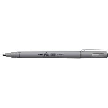
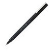
油性染料極細サインペン ピン
uni(三菱鉛筆)¥899税込¥9891箱(10本)当日出荷極細筆記線の油性マーカーです 細かな筆記向きです用途工業用として各種素材・部品へのマーキング・識別用。トラスコ品番857-6559入数10本線の太さ極細筆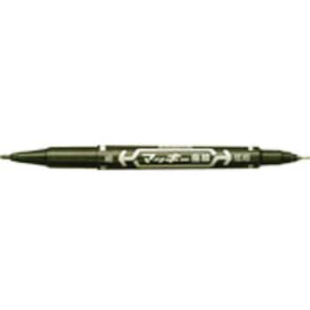
マッキー極細
ゼブラ(72件のレビュー)¥99~税込¥109~1本ほか当日出荷1本で太細両用が使える便利な油性マーカーです。 また、極太から極細までの線幅やインク色のラインナップが揃っています。 速乾性・耐水性で、紙・布・木・ダンボール・ガラス・プラスチック・金属・ビニール類などに幅広く利用できます。全長(mm)141.8質量(g)8.5線幅(mm)細/1.0~1.3、極細/0.5商品タイプ使い切り本体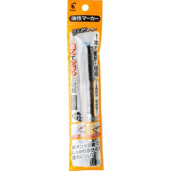
油性ツインマーカー 細・極細
パイロット(40件のレビュー)¥94~税込¥103~1本ほか当日出荷から5日以内出荷ツインタイプの油性マーカー。パイロット独自のコイピタインクを搭載し、一般的な油性マーカーではインクが定着しにくいクラフトテープ、ポリ袋、マスキングテープにもしっかり書けます。 ペン先は細字、極細字のため事務所内での使用に適しております。用途ラベル付け、修理やDIY、倉庫管理、キャンプ用品全長(mm)138タイプツインエコマーク認定認定方式ツインキャップ式線幅(mm)細/0.5、極細/0.4インク油性染料グリーン購入法適合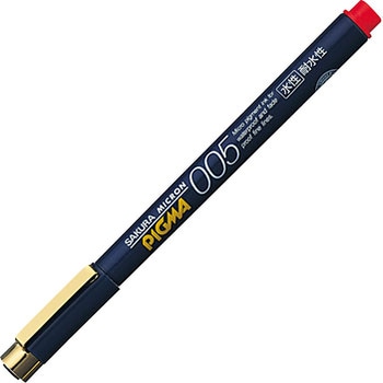
ピグマ005
サクラクレパス(7件のレビュー)¥199税込¥2191本当日出荷ピグマシリーズは顔料インキを使用していますので、 水に流れにくい耐水性です。 直射日光があたっても色あせしない耐光性です。 ラインマーカーを上から引いてもにじみません。用途フロッピーディスク等のラベル 書き。ノート・手紙・イラスト。 コピーファクシミリ原稿。 感熱複写・製版。図面・保存書類・ 重要書類。(特許登録済、商標登録済、意匠登録済)線幅(mm)約0.05材質軸・キャップ・尾栓:PP、クリップ:スチール、先栓:真鍮、ペン先:POM全長(mm)135質量(g)9最大径(Φmm)10.5インク水性顔料商品タイプ使い切り本体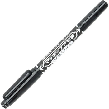
マッキーケア極細つめ替えタイプ
ゼブラ(155件のレビュー)¥99~税込¥109~1本ほか当日出荷インクが切れたら詰め替えが出来る油性マーカー。 アルコール系インクを使用しています。速乾性・耐水性。 1本で細・極細書き両用。用途紙・布・木・ダンボール・ガラス・プラスチック・金属・ビニール類など幅広くご利用になれます。軸径(Φmm)13.0(最大径)全長(mm)140質量(g)9タイプツインエコマーク認定認定材質(軸)再生樹脂線幅(mm)細/1.0~1.3、極細/0.5材質(キャップ)再生樹脂インク油性インクグリーン購入法適合商品タイプ詰替式本体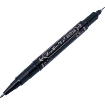
マッキーケア超極細 使い切りタイプ
ゼブラ(16件のレビュー)¥99税込¥1091本当日出荷用途紙・布・木・ダンボール・ガラス・プラスチック・金属・ビニール類など幅広くご利用になれます。全長(mm)140.7質量(g)9.4タイプツインエコマーク認定認定線幅(mm)超極細/0.3、極細/0.7インク油性インク入数1本グリーン購入法適合商品タイプ使い切り本体エコマーク認定番号18 112 022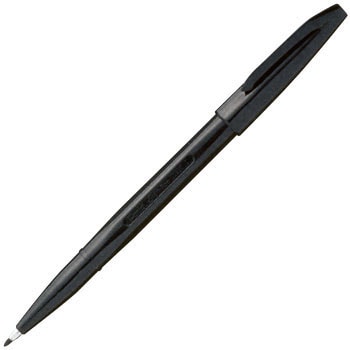
サインペン
ぺんてる(アストラム)(82件のレビュー)¥83~税込¥91~1本ほか当日出荷なめらかなタッチのアクリル繊維ペン先。筆記線幅0.8mm。再生材使用率83%(プラスチック)。線幅(mm)0.8材質(軸)再生PP材質(キャップ)再生PP材質(尾栓)再生PE材質(ペン先)アクリル繊維(先金/真鍮)タイプシングルインク水性染料商品タイプ使い切り本体線の太さ細字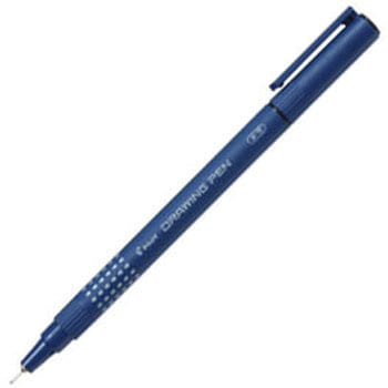
水性ドローイングペン
パイロット(2件のレビュー)¥199税込¥2191本当日出荷水性顔料インキを搭載。耐水性で美しい筆跡の製図・デザイン・証券用ペン。極細サインペンとして、帳簿や手帳などの日常使いにも最適です。 筆跡は顔料インキのため、耐水性・耐光性が抜群。インキ濃度も高く、乾燥性に優れています。筆跡幅は6種、インキ色は3色です。 インキ・サーキュレーション・システム搭載 ペン先のインキを循環させるシステムがキャップ内に装備されております。この機能により、書き出しをスムーズにすることを可能にし、カスレも少なく、顔料インキでも濃淡のない筆跡を得ることができます。全長(mm)141種類ドローイングペン方式キャップ式最大径(Φmm)10.5インク水性顔料商品タイプ使い切り本体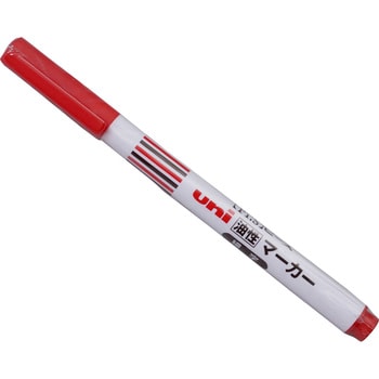
ピース 油性マーカー 丸芯・細字
uni(三菱鉛筆)(7件のレビュー)¥90税込¥991本当日出荷商品タイプ使い切り本体タイプシングル線幅(mm)0.7~0.9質量(g)8.4材質(軸)再生PP樹脂インク油性入数1本寸法(軸径Φ×厚さ×全長)(mm)10.7×14.3×139.1グリーン購入法適合線の太さ細字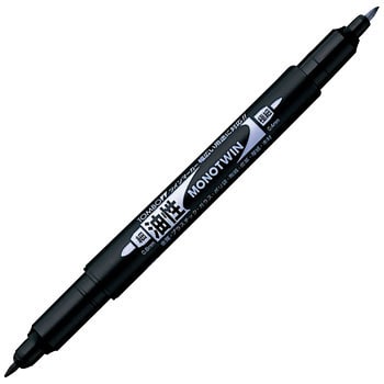
モノツイン極細E
トンボ鉛筆(42件のレビュー)¥99税込¥1091本当日出荷一本で幅広い用途に対応!! 細・極細のツインタイプ!!質量(g)9タイプツインエコマーク認定認定材質(軸)再生ポリプロピレン線幅(mm)細/0.8、極細/0.4インク油性材質(ペン芯)細/アクリル・極細/ポリアセタール入数1本グリーン購入法適合寸法(軸径Φ×全長)(mm)16×141商品タイプ使い切り本体エコマーク認定番号15 112 023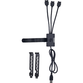
UNIFAN用HUB
LIAN LI¥3,398税込¥3,7381個6日以内出荷マザーボード背面のUSB2.0 A 1ポートから、内部USB2.0 9pin 3ポートに拡張するUSB HUBです。 TL/TL LCDを除くすべてのUNI FANシリーズのコントローラー、およびSTRIMERのコントローラー、Galahad II Trinityおよび、Galahad II LCDに対応しています。 ケースカラーに合わせ、黒と白の2色のバリエーションがあります。 ケーブルを引き込む際にケーブルを通す穴が開いた専用のPCIブラケットカバーが付属します。仕様HUBサイズ:60×39×11mm質量(g)60固定方法マジックテープ保証期間1年間ケーブル長(cm)USB A(オス) 約60、USB 9ピン 約14×3本USBポート数3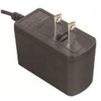
ACアダプタ 12V 1A
UNIFIVE¥2,198税込¥2,4181個当日出荷Unifive UV313 シリーズ壁面取り付け型 AC/DC アダプタは、定格電力が 10 W です。短絡保護、過電圧保護、過電流保護の機能を備えています。動作温度は最高 40 ℃ です。MP3 プレーヤー、携帯型 GPS、PDA、超小型サイズ 軽量 高エネルギー効率仕様●タイプ:AC/DCアダプタ●出力電圧:12V●入力電圧:100 → 240V ac●出力電流:1A●入力コネクタ:2 Pin Plug●定格電力:10WタイプAC/DC アダプタ規格安全認証、信頼性、省エネ、ROHS 2、LPS、EMC定格電力(W)10入力電圧(V)90(Min.)、100~240(Typ.)、264(Max.)出力電流(A)1保存温度(℃)-20~65(Free Convection、Sea Level)プラグPL03B入力周波数(Hz)47(Min.)、50/60(Typ.)、63(Max.)動作温度(℃)0~40(Free Convection、Sea Level)アズワン品番65-7222-29定格出力電圧(DC V)12動作湿度(%RH)5~95(結露なし)保存湿度(%RH)5~95(結露なし)入力コネクタ2 Pin Plug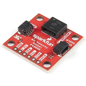
SparkFun Air Velocity Sensor Breakout - FS3000-1005 Qwiic
SPARKFUN¥17,980税込¥19,7781個33日以内出荷。Description。Need to keep track of the airflow in your data center or around your servers? How about making sure your HVAC and air control systems are functioning at full capacity? Well, the new SparkFun FS3000-1005 Air Velocity Sensor Breakout can help you with all that and more! It's super easy and super quick(Qwiic!)to hook up.。This breakout board is focused around Renesas' FS3000-1005, a surface-mount air velocity module with a range of 0-7.2m/s(0-16.2mph). It utilizes a MEMS thermopile-based sensor, features a digital output with 12-bit resolution and comprises a "solid" thermal isolation technology and silicon carbide coating to protect it from abrasive wear and water condensation.。We've written an Arduino library to help you get started quickly. You can download the library through the Arduino library manager by searching 'SparkFun Air Velocity' or you can get the GitHub repo as a .zip file and install the library from there.。The SparkFun Qwiic Connect System is an ecosystem of I2C sensors, actuators, shields and cables that make prototyping faster and less prone to error. All Qwiic-enabled boards use a common 1mm pitch, 4-pin JST connector. This reduces the amount of required PCB space, and polarized connections mean you can't hook it up wrong.。Get Started with the Qwiic Air Velocity Sensor Breakout。Features。I2C address:0x28。Air flow speed:0 - 7.23 m/sec(0 - 16.17mph)。Accuracy:5 % of full scale flow range。12-bit resolution。Input Voltage:2.7-3.3V。Average current draw:10mAアズワン品番67-0427-58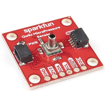
SparkFun Qwiic MicroPressure Sensor
SPARKFUN¥24,980税込¥27,4781個33日以内出荷Description。The SparkFun Qwiic MicroPressure Sensor is a miniature breakout equipped with Honeywell's 25psi piezoresistive silicon pressure sensor. This MicroPressure Sensor offers a calibrated and compensated pressure sensing range of 60mbar to 2.5bar, easy to read 24 bit digital I2C output, and can be calibrated and compensated over a specific temperature range for sensor offset, sensitivity, temperature effects, and non-linearity using an on-board Application Specific Integrated Circuit(ASIC). With its ultra-low power consumption and Qwiic ports, you've got yourself a power packed little sensor!。Each Qwiic MicroPressure Sensor has a calibrated pressure sensing range from 1-25psi and a power consumption rate as low as 0.01mW typ. average power, 1Hz measurement frequency for ultimate portability. Used in multiple medical(blood pressure monitoring, negative pressure wound therapy), industrial(air braking systems, gas and water meters), and consumer uses(coffee machines, humidifiers, air beds, washing machines, dishwashers), the SparkFun Qwiic MicroPressure Sensor is a great addition to the SparkFun Qwiic ecosystem!。The SparkFun Qwiic Connect System is an ecosystem of I2C sensors, actuators, shields and cables that make prototyping faster and less prone to error. All Qwiic-enabled boards use a common 1mm pitch, 4-pin JST connector. This reduces the amount of required PCB space, and polarized connections mean you can't hook it up wrong.。Get Started with the SparkFun Qwiic MicroPressure Hookup Guide。Features。Pressure Type:Absolute。Operating Pressure:25psi(172.37kPa)。I2C Address:0x18。Accuracy:±0.25%。Voltage - Supply:1.8V-3.6V。Port Size:Male - 0.1"(2.5mm)Tube。Port Style:Barbless。Maximum Pressure:60psi(413.69kPa)。Compatible with a variety of liquid media。2x Qwiic Connectorsアズワン品番67-0427-25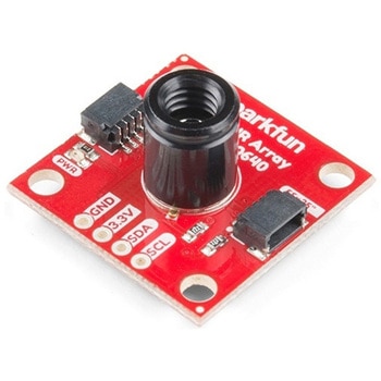
SparkFun IR Array Breakout - 55 Degree FOV, MLX90640 Qwiic
SPARKFUN¥22,980税込¥25,2781個33日以内出荷Description。It's time to say hip hip array for this IR Breakout! The MLX90640 SparkFun IR Array Breakout is equipped with a 32x24 array of thermopile sensors creating, in essence, a low resolution thermal imaging camera. With this breakout you can detect surface temperatures from many feet away with an accuracy of ±1.5℃(best case). To make it even easier to get your infrared image, all communication is enacted exclusively via I2C, utilizing our handy Qwiic system. However, we still have broken out 0.1"-spaced pins in case you prefer to use a breadboard.。This specific IR Array Breakout features a。55°x35°。field of view with a temperature measurement range of -40℃-300℃. The MLX90640 IR Array has pull up resistors attached to the I2C bus; both can be removed by cutting the traces on the corresponding jumpers on the back of the board. Please be aware that the MLX90640 requires complex calculations by the host platform so a regular Arduino Uno(or equivalent)doesn't have enough RAM or flash to complete the complex computations required to turn the raw pixel data into temperature data. You will need a microcontroller with 20,000 bytes or more of RAM. To achieve this, we recommend a Teensy 3.1 or above.。The SparkFun Qwiic connect system is an ecosystem of I2C sensors, actuators, shields and cables that make prototyping faster and less prone to error. All Qwiic-enabled boards use a common 1mm pitch, 4-pin JST connector. This reduces the amount of required PCB space, and polarized connections mean you can't hook it up wrong.。Get Started with the SparkFun IR Array Breakout Guide。Features。Operating Voltage:3V-3.6V。Current Consumption:~18mA。Field of View:55°x35°。Measurement Range:-40℃-300℃。Resolution:±1.5℃。Refresh Rate:0.5Hz-64Hz。I2C Address:0x33。2x Qwiic Connection Portsアズワン品番67-0426-88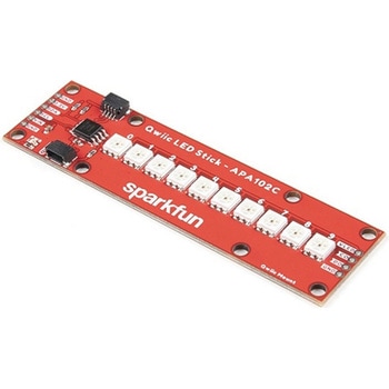
SparkFun Qwiic LED Stick - APA102C
SPARKFUN¥3,500税込¥3,8501個33日以内出荷Description。The SparkFun Qwiic LED Stick features ten addressable APA102 LEDs, making it easy to add full color LED control using I2C. Write to individual LEDs to display a count in binary, or write to the whole strip for cool lighting effects. You can even add more LEDs to the end if you need to. We've written an Arduino library and Python package that take care of the I2C and communication to the LEDs so all you have to do is decide what color each LED should be.。The LED Stick has a default I2C address of 0x23 but can be changed with a simple command, allowing you to control up to 100 LEDs(10 Qwiic LED Sticks)on a single bus! The address can also be changed to 0x22 by closing the solder jumper on the back of the board.。This board is one of our many Qwiic compatible boards! Simply plug and go. No soldering, no figuring out which is SDA or SCL, and no voltage regulation or translation required!。Warning:Using a lot of LEDs can draw a lot of current. Make sure to consider the power limits of your setup. If you expect your LED chain to draw more than 600mA of current, connect your external supply directly to VLED. Closing the jumper from VLED to VCC will add a 4.7uF decoupling capacitor.。The SparkFun Qwiic Connect System is an ecosystem of I2C sensors, actuators, shields and cables that make prototyping faster and less prone to error. All Qwiic-enabled boards use a common 1mm pitch, 4-pin JST connector. This reduces the amount of required PCB space, and polarized connections mean you can't hook it up wrong.。Get Started with the Qwiic LED Stick Guide。Features。10x APA102C addressable LEDs driven by an ATTiny85。Default I2C Address:0x23(Adjustable to 0x22 via Jumper)。2x Qwiic Connectorsアズワン品番67-0421-83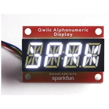
SparkFun Qwiic Alphanumeric Display - White
SPARKFUN¥2,998税込¥3,2981個33日以内出荷Description。We are quite familiar with seven-segment displays. We see them on our alarm clocks, ovens, and microwaves. By adding more segments to each digit you can display more than just numbers! Introducing the brand new SparkFun Qwiic Alphanumeric Display. These white fourteen-segment digits allow you display all sorts of numbers, characters, and symbols. With Qwiic, simply plug it in and go. No soldering, no figuring out which is SDA or SCL, and no voltage regulation or translation required!。The SparkFun Alphanumeric Display Arduino library makes printing strings to the display as easy as calling the print()function. With this library, you'll be able to send I2C commands to the VK16K33 LED driver chip to light up segments(including the decimal point or colon)and even scroll your string across the display. You can download the library through the Arduino library manager by searching 'SparkFun Alphanumeric Display' or you can get the GitHub repo as a .zip file and install the library from there.。The VK16K33 also supports I2C address configuration. Simply close a combination of the address jumpers on the back and you can communicate with up to four displays on the same bus. Our slim board design also features detachable stand off holes, vertical Qwiic connectors, and internal mounting holes.。The SparkFun Qwiic Connect System is an ecosystem of I2C sensors, actuators, shields and cables that make prototyping faster and less prone to error. All Qwiic-enabled boards use a common 1mm pitch, 4-pin JST connector. This reduces the amount of required PCB space, and polarized connections mean you can't hook it up wrong.。Get Started with the Qwiic Alphanumeric Display Hookup Guide。Features。White display。Operating Voltage:3.3V。Integrated RC oscillator。Maximum display segment numbers:128 patterns。13×3 matrix key scan circuit。16-step dimming circuit。I2C Addresses:0x70(0x71, 0x72, 0x73)。2x Qwiic connectors。2x Wall Mounting Pointsアズワン品番67-0421-87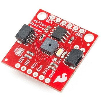
SparkFun Spectral Sensor Breakout - AS7263 NIR Qwiic
SPARKFUN¥9,998税込¥10,9981個33日以内出荷Description。The SparkFun AS7263 Near Infrared(NIR)Spectral Sensor Breakout brings spectroscopy to the palm of your hand, making it easier than ever to measure and characterize how different materials absorb and reflect different wavelengths of light. The AS7263 Breakout is unique in its ability to communicate by both an I2C interface and serial interface using AT commands. Hookup is easy, thanks to the Qwiic connectors attached to the board --- simply plug one end of the Qwiic cable into the breakout and the other into one of the Qwiic shields, then stack the board on a development board. You'll be ready to upload a sketch to start taking spectroscopy measurements in no time.。The AS7263 spectrometer detects wavelengths in the visible range at 610, 680, 730, 760, 810 and 860nm of light, each with 20nm of full-width half-max detection. The board also has multiple ways for you to illuminate objects that you will try to measure for a more accurate spectroscopy reading. There is an onboard LED that has been picked out specifically for this task, as well as two pins to solder your own LED into.。Note:The I2C address of the AS7263 is 0x49 and is hardware defined. A multiplexer/Mux is required to communicate to multiple AS7263 sensors on a single bus. If you need to use more than one AS7263 sensor consider using the Qwiic Mux Breakout.。The SparkFun Qwiic Connect System is an ecosystem of I2C sensors, actuators, shields and cables that make prototyping faster and less prone to error. All Qwiic-enabled boards use a common 1mm pitch, 4-pin JST connector. This reduces the amount of required PCB space, and polarized connections mean you can't hook it up wrong.。Get Started with the SparkFun AS726X Spectral Sensor Breakout Guide。Features。6 near-IR channels:610nm, 680nm, 730nm, 760nm, 810nm and 860nm, each with 20nm FWHM。NIR filter set realized by silicon interference filters。16-bit ADC with digital access。Programmable LED drivers。2.7V to 3.6V with I2C interface。2x Qwiic connectorsアズワン品番67-0426-70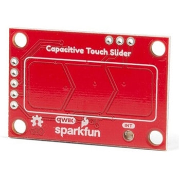
SparkFun Capacitive Touch Slider - CAP1203 Qwiic
SPARKFUN¥2,498税込¥2,7481個33日以内出荷。Description。Do you want to replace a slider or a button on your art project or science experiment with a more interesting interface? This Capacitive Touch Slider is a "Qwiic" and easy way to add capacitive touch to your next project. With the board's built in touch pads, you can immediately start playing with the touch capabilities as three unique touch inputs or as a slider. You can also enable a touch input to act as a power button, customize the sensitivity for your own touch pads, and play with the interrupt alert LED. Utilizing our Qwiic system, no soldering is required to connect it to the rest of your system. However, we have broken out 0.1"-spaced pins in case you prefer to use a breadboard or create your own touch pads.。On the front of the board, there is an arrow shape which contains three separate capacitive touch pads. We also broke out the capacitive touch sensor lines as plated through-holes on the top of the board. You can use these pins to connect to your own capacitive touch pads. The CS1 pin connects to the left pad, the CS2 pin connects to the middle pad, and the CS3 pin connects to the right pad.。NOTE:The I2C address of the CAP1203 is 0x28 and is hardware defined. A multiplexer/Mux is required to communicate to multiple CAP1203 sensors on a single bus. If you need to use more than one CAP1203 sensor consider using the Qwiic Mux Breakout.。The SparkFun Qwiic connect system is an ecosystem of I2C sensors, actuators, shields and cables that make prototyping faster and less prone to error. All Qwiic-enabled boards use a common 1mm pitch, 4-pin JST connector. This reduces the amount of required PCB space, and polarized connections mean you can't hook it up wrong.。Get Started with the SparkFun Capacitive Touch Slider Guide。Features。Capacitive Touch。3 unique capacitive touch inputs。Features。Emulated slider。Power button setting。Programmable sensitivity。Automatic recalibration。I2C Address:0x28。Qwiic Enabled。Operating Range。Supply Voltage:3.3V - 5Vアズワン品番67-0427-06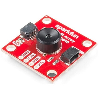
SparkFun IR Array Breakout - 110 Degree FOV, MLX90640 Qwiic
SPARKFUN¥22,980税込¥25,2781個33日以内出荷Description。It's time to say hip hip array for this IR Breakout! The MLX90640 SparkFun IR Array Breakout is equipped with a 32x24 array of thermopile sensors creating, in essence, a low resolution thermal imaging camera. With this breakout you can detect surface temperatures from many feet away with an accuracy of ±1.5℃(best case). To make it even easier to get your low-resolution infrared image, all communication is enacted exclusively via I2C, utilizing our handy Qwiic system. However, we still have broken out 0.1"-spaced pins in case you prefer to use a breadboard.。This specific IR Array Breakout features a 110°x75° field of view with a temperature measurement range of -40℃-300℃. The MLX90640 IR Array has pull up resistors attached to the I2C bus; both can be removed by cutting the traces on the corresponding jumpers on the back of the board. Please be aware that the MLX90640 requires complex calculations by the host platform so a regular Arduino Uno(or equivalent)doesn't have enough RAM or flash to complete the complex computations required to turn the raw pixel data into temperature data. You will need a microcontroller with 20,000 bytes or more of RAM. To achieve this, we recommend a Teensy 3.1 or above.。Note:The I2C address of the MLX90640 is 0x33 and is hardware defined. A multiplexer/Mux is required to communicate to multiple MLX90640 sensors on a single bus. If you need to use more than one MLX90640 sensor consider using the Qwiic Mux Breakout.。The SparkFun Qwiic connect system is an ecosystem of I2C sensors, actuators, shields and cables that make prototyping faster and less prone to error. All Qwiic-enabled boards use a common 1mm pitch, 4-pin JST connector. This reduces the amount of required PCB space, and polarized connections mean you can't hook it up wrong.。Get Started with the SparkFun IR Array Breakout Guide。Features。Operating Voltage:3V-3.6V。Current Consumption:~18mA。Field of View:110°x75°。Measurement Range:-40℃-300℃。Resolution:±1.5℃。Refresh Rate:0.5Hz-64Hz。I2C Address:0x33。2x Qwiic Connection Portsアズワン品番67-0426-87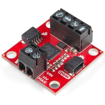
SparkFun Qwiic Motor Driver
SPARKFUN¥6,698税込¥7,3681個33日以内出荷。Description。The SparkFun Qwiic Motor Driver takes all the great features of the Serial Controlled Motor Driver(SCMD)and miniaturizes them, adding Qwiic ports for plug and play functionality. Boasting the same 4245 PSOC and 2-channel motor ports as the SCMD, the SparkFun Qwiic Motor Driver is designed to communicate over I2C to make setting up your next robotic project as fast and easy as possible! Utilizing our handy Qwiic system and screw terminals for motor and power hook-up, no soldering is required to connect it to the rest of your system.。With 1.2A steady state drive per channel(1.5A peak)and 127 levels of DC drive strength, this little Qwiic board is perfect for your small DC motor driver needs. Since the Qwiic Motor Driver is a 3.3V logic device, you'll need to use a logic level converter to interface to 5V.。The I2C address of the Qwiic Motor Driver is 0x5D and is jumper selectable to 0x58, 0x59, 0x5A, 0x5B, ... 0x63.。The SparkFun Qwiic Connect System is an ecosystem of I2C sensors, actuators, shields and cables that make prototyping faster and less prone to error. All Qwiic-enabled boards use a common 1mm pitch, 4-pin JST connector. This reduces the amount of required PCB space, and polarized connections mean you can't hook it up wrong.。Need a custom board? This component can be found in SparkFun's A La Carte board builder. You can have a custom design fabricated with this component - and your choice of hundreds of other sensors, actuators and wireless devices - delivered to you in just a few weeks.。Get Started With the Qwiic Motor Driver Hookup Guide。Features。1.5 A peak drive per channel, 1.2 A steady state。Operates from 3 to 11 Volts with 12V absolute max。3.3V default VCC and logic。127 levels of DC drive strength.。Controllable by I2C or TTL UART signals。Direction inversion on a per motor basis。Global Drive enable。Exposed small heat sink shape。Several I2C addresses, default UART bauds available。Adjustable I2C Address:0x5D Default。2x Qwiic Connectors。。Documents。Schematic。Eagle Files。Board Dimensions。Hookup Guide。Arduino Library。Python Module。Github Hardware Repoアズワン品番67-0426-33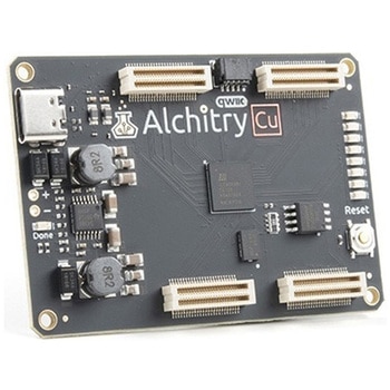
Alchitry Cu FPGA Development Board Lattice iCE40 HX
SPARKFUN¥15,980税込¥17,5781個33日以内出荷Description。If you are not needing a lot of power to start your FPGA adventure, or are looking for a more economical option, the Alchitry Cu FPGA Development Board might be the perfect option for you! The Alchitry Cu is a "lighter" FPGA version than the Alchitry Au but still offers something completely unique. FPGAs, or Field-Programmable Gate Arrays, are an advanced development board type for engineers and hobbyists alike to experience the next step in programming with electronics. The Cu truly exemplifies the trend of more affordable and increasingly powerful FPGA boards arriving each year. This board is a fantastic starting point into the world of FPGAs and the heart of your next project. Finally, now that this board is built by SparkFun, we added a Qwiic connector for easy I2C integration!。The Alchitry Cu uses the Lattice iCE40 HX FPGA with 7680 logic cells and is supported by the open source tool chain Project IceStorm. The Cu possesses 79 IO pins with eight general purpose LEDs; a 100MHz on-board clock that can be manipulated internally by the FPGA; a USB-C connector to configure and power the board; and a USB to serial interface for data transfer.。By adding stackable expansion boards similar to shields or HATs called "Elements," the Alchitry Cu is able to expand its own hardware capabilities by adding prototyping spaces, buttons, LEDs, and more!。The SparkFun Qwiic Connect System is an ecosystem of I2C sensors, actuators, shields and cables that make prototyping faster and less prone to error. All Qwiic-enabled boards use a common 1mm pitch, 4-pin JST connector. This reduces the amount of required PCB space, and polarized connections mean you can't hook it up wrong.。Get Started with our Learning FPGA Tutorials。Features。Lattice iCE40-HX8K FPGA - 7680 logic elements。79 IO pins(3.3V logic level)。USB-C to configure and power the board。Eight general purpose LEDs。One button(typically used as a reset)。100MHz on-board clock(can be multiplied internally by the FPGA)。Powered with 5V through USB-C port, 0.1" holes, or headers。USB to serial interface for data transfer(up to 12Mbaud)。Qwiic Connector。Dimensions of 65mm×45mm。。Examples。First FPGA Project - Getting Fancy with PWM。External IO and Metastabilityアズワン品番67-0423-08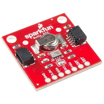
SparkFun Real Time Clock Module - RV-1805 Qwiic
SPARKFUN¥7,798税込¥8,5781個33日以内出荷Description。Get with the times, already! This SparkFun Real Time Clock(RTC)Module is a Qwiic-enabled breakout board for the RV-1805 chipset. The RTC is ultra-low power(running at only about 22nA in its lowest power setting)so it can use a supercapacitor for backup power instead of a normal battery. This means you get plenty of charge and discharge cycles without any degradation to the "battery." To make it even easier to get your readings, all communication is enacted exclusively via I2C, utilizing our handy Qwiic system so no soldering is required to connect it to the rest of your system. However, we still have broken out 0.1"-spaced pins in case you prefer to use a breadboard.。This RTC module's built in RV-1805 has not one, but two internal oscillators:a 32.768kHz tuning fork crystal and a low power RC based oscillator and can automatically switch between the two using the more precise crystal to correct the RC oscillator every few minutes. This feature allows the module to maintain a very accurate date and time with the worst case being +/- about three minutes over a year. The RV-1805 also has a built in trickle charger so as soon as the RTC is connected to power the it will be fully charged in under 10 minutes and has the ability to switch power to other systems allowing it to directly turn on or off a power hungry device such as a microcontroller or RF engine.。There is also the option to add a battery to the board if the supercapacitor just isn't going keep your project powered long enough(keep in mind, the supercap can hypothetically make the board keep time for around 35 days), you can solder on an external battery. That means you can let board sit with no power or connection to the outside world and the current hour/minute/second/date will be maintained.。Note:。The I2C address of the RV-1805 is 0x69 and is hardware defined. A multiplexer/Mux is required to communicate to multiple RV-1805 sensors on a single bus. If you need to use more than one RV-1805 sensor consider using the Qwiic Mux Breakout.。The SparkFun Qwiic connect system is an ecosystem of I2C sensors, actuators, shields and cables that make prototyping faster and less prone to error. All Qwiic-enabled boards use a common 1mm pitch, 4-pin JST connector. This reduces the amount of required PCB space, and polarized connections mean you can't hook it up wrong.。Get Started with the RV-1805 Real Time Clock Module Guide。Features。Operating Voltage(Startup):1.6V - 3.6V。Operating Voltage(Timekeeping):1.5V - 3.6V。Operating Temperature:-40℃ - 85℃。Time Accuracy:±2.0 ppm。Current Consumption:22nA(Typ.)。I2C Address:0xD2。Supercapacitor for Backup Power。2x Internal Oscillators。2x Qwiic Connectorsアズワン品番67-0420-02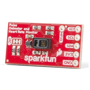
SparkFun Pulse Oximeter and Heart Rate Sensor - MAX30101 & MAX32664 Qwiic
SPARKFUN¥13,980税込¥15,3781個33日以内出荷Description。The SparkFun Pulse Oximeter and Heart Rate Sensor is an I2C based biometric sensor, utilizing two chips from Maxim Integrated:the MAX32664 Biometric Sensor Hub and the MAX30101 Pulse Oximetry and Heart Rate Module. While the latter does all the sensing, the former is an incredibly small and fast Cortex M4 processor that handles all of the algorithmic calculations, digital filtering, pressure/position compensation, advanced R-wave detection, and automatic gain control. We've provided a Qwiic connector to easily connect to the I2C data lines but you will also need to connect to two additional lines. This board is very small, measuring at 1in×0.5in(25.4mm×12.7mm), which means it will fit nicely on your finger without all the bulk.。The MAX30101 does all the sensing by utilizing its internal LEDs to bounce light off the arteries and arterioles in your finger's subcutaneous layer and sensing how much light is absorbed with its photodetectors. This is known as photoplethysmography. This data is passed onto and analyzed by the MAX32664 which applies its algorithms to determine heart rate and blood oxygen saturation(SpO2). SpO2 results are reported as the percentage of hemoglobin that is saturated with oxygen. It also provides useful information such as the sensor's confidence in its reporting as well as a handy finger detection data point. To get the most out of the sensor we've written an Arduino Library to make it easy to adjust all the possible configurations.。The SparkFun Qwiic connect system is an ecosystem of I2C sensors, actuators, shields and cables that make prototyping faster and less prone to error. All Qwiic-enabled boards use a common 1mm pitch, 4-pin JST connector. This reduces the amount of required PCB space, and polarized connections mean you can't hook it up wrong.。Get Started with the Pulse Oximeter and Heart Rate Monitor Hookup Guide。Features。SparkFun Pulse Oximeter and Heart Rate Sensor。MAX30101 and MAX32664 sensor and sensor hub。Qwiic connectors for power and I2C interface。I2C Address:0x55。MAX30101 - Pulse Oximeter and Heart-Rate Sensor。Heart-Rate Monitor and Pulse Oximeter Sensor in LED Reflective Solution。Integrated Cover Glass for Optimal, Robust Performance。Ultra-Low Power Operation for Mobile Devices。Fast Data Output Capability。Robust Motion Artifact Resilience。MAX32664 - Ultra-Low Power Biometric Sensor Hub。Biometric Sensor Hub Solution。Finger-Based Algorithms Measure Pulse Heart Rate and Pulse Blood Oxygenation Saturation(SpO2)。Both Raw and processed data are available。Basic Peripheral mix optimizes size and performanceアズワン品番67-0426-96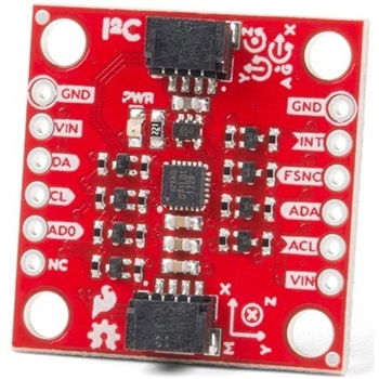
SparkFun 9DoF IMU Breakout - ICM-20948 Qwiic
SPARKFUN¥7,298税込¥8,0281個33日以内出荷。Description。The SparkFun 9DoF IMU Breakout incorporates all the amazing features of Invensense's ICM-20948 into a Qwiic-enabled breakout board complete with a logic shifter and broken out GPIO pins for all your motion sensing needs. The ICM-20948 itself is an extremely low powered, I2C and SPI enabled 9-axis motion tracking device that is ideally suited for smartphones, tablets, wearable sensors, and IoT applications. Utilizing our handy Qwiic system, no soldering is required to connect it to the rest of your system. However, we still have broken out 0.1"-spaced pins in case you prefer to use a breadboard.。In addition to the 3-Axis Gyroscope with four selectable ranges, 3-Axis Accelerometer, again with four selectable ranges, and 3-axis magnetometer with an FSR to ±4900μT, the ICM-20948 also includes a Digital Motion Processor that offloads the computation of motion sensing algorithms from the detectors, allowing optimal performance of the sensors. We've also broken out all the ICM-20948 pin functionality to GPIO and labeled them I2C on the front, SPI on the back for ease of identification.。Note:The I2C address of the ICM-20948 is 0x69 and is jumper selectable to 0x68. A multiplexer/Mux is required to communicate to multiple ICM-20948 sensors on a single bus. If you need to use more than one ICM-20948 sensor consider using the Qwiic Mux Breakout.。The SparkFun Qwiic Connect System is an ecosystem of I2C sensors, actuators, shields and cables that make prototyping faster and less prone to error. All Qwiic-enabled boards use a common 1mm pitch, 4-pin JST connector. This reduces the amount of required PCB space, and polarized connections mean you can't hook it up wrong.。Need a custom board? This component can be found in SparkFun's A La Carte board builder. You can have a custom design fabricated with this component - and your choice of hundreds of other sensors, actuators and wireless devices - delivered to you in just a few weeks.。Get Started with the SparkFun ICM-20948 9DoF IMU Guide。Features。1.95 V to 3.6 V supply voltage。Triple-axis MEMS gyroscope with user-programmable full-scale range of ±250 dps, ±500 dps, ±1000 dps, and ±2000 dps。Triple-axis MEMS accelerometer with programmable full scale range of ±2g, ±4g, ±8g, and ±16g。Triple-axis silicon monolithic Hall-effect magnetic sensor with full scale measurement range to ±4900 μT。I2C at up to 100 kHz(standard-mode)or up to 400 kHz(fast-mode)or SPI at up to 7 MHz for communicationwith registers。On-board digital motion processor(DMP)。Digital-output temperature sensor。2x Qwiic Connection Ports。I2C Address:0x69(0x68 with Jumper)。。Documents。Schematic。Eagle Files。Hookup Guide。Datasheet(ICM-20948)。Arduino Library。Python Support(Qwiic_Py)。GitHub Hardware Repoアズワン品番67-0427-05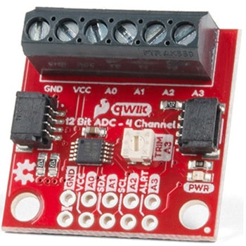
QWIIC 12BIT 4CHANNEL ADS1015
SPARKFUN¥5,498税込¥6,0481個33日以内出荷Description。A lot of the time you just need to add more analog inputs to solve a problem. It happens. The SparkFun Qwiic 12 Bit ADC can provide four channels of I2C controlled ADC input to your Qwiic enabled project. These channels can be used as single-ended inputs, or in pairs for differential inputs. What makes this even more powerful is that it has a programmable gain amplifier that lets you "zoom in" on a very small change in analog voltage(but will still effect your input range and resolution). Utilizing our handy Qwiic system, no soldering is required to connect it to the rest of your system. However, we still have broken out 0.1"-spaced pins in case you prefer to use a breadboard.。The ADS1015 uses its own internal voltage reference for measurements, but a ground and 3.3V reference are also available on the pin outs for users. This ADC board includes screw pin terminals on the four channels of input, allowing for solderless connection to voltage sources in your setup. It also has an address jumper that lets you choose one of four unique addresses(0x48, 0x49, 0x4A, 0x4B). With this, you can connect up to four of these on the same I2C bus and have sixteen channels of ADC. The maximum resolution of the converter is 12-bits in differential mode and 11-bits for single-ended inputs. Step sizes range from 125μV per count to 3mV per count depending on the full-scale range(FSR)setting.。We have included an onboard 10K trimpot connected to channel A3. This is handy for initial setup testing and can be used as a simple variable input to your project. But don't worry, we added an isolation jumper so you can use channel A3 however you'd like.。Note:The I2C address of the ADS1015 is 0x48 and is jumper selectable to 0x49, 0x4A, 0x4B. A multiplexer/Mux is required to communicate to multiple ADS1015 sensors on a single bus. If you need to use more than one ADS1015 sensor consider using the Qwiic Mux Breakout.。The SparkFun Qwiic connect system is an ecosystem of I2C sensors, actuators, shields and cables that make prototyping faster and less prone to error. All Qwiic-enabled boards use a common 1mm pitch, 4-pin JST connector. This reduces the amount of required PCB space, and polarized connections mean you can't hook it up wrong.。Get Started with the SparkFun Qwiic 12-Bit ADC Hookup Guide。Features。ADS1015。Operating Voltage(VDD):2.0V-5.5V。(Note:When powering with a Qwiic cable, the input range is only 3.3v)。Operating Temperature:-40℃ to 125℃。Operation Modes:Single-Shot, Continuous-Conversion(Default), and Duty Cycling。Analog Inputs:Measurement Type:Single-Ended(Default)。Input Voltage Range:GND to VDD。Full Scale Range(FSR):±.256V to ±6.114V(Default:2.048V)。Resolution:12-bit(Differential)or 11-bit(Single-Ended)。LSB size:0.125mV - 3mV(Default:1 mV)。Sample Rate:128 Hz to 3.3 kHz(Default:1600SPS)。Current Consumption(Typical):150μA-200μA。I2C Address:0x48(Default), 0x49, 0x4A, or 0x4B。Screw pin terminals for solderless connection to voltage sources。Four unique I2C addresses:0x48。0x49。0x4A。0x4B。2x Qwiic connection ports。Onboard 10K trimpotアズワン品番67-0360-13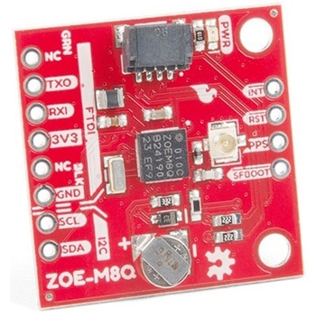
SparkFun GPS Breakout - ZOE-M8Q Qwiic
SPARKFUN¥14,980税込¥16,4781個33日以内出荷Description。The SparkFun ZOE-M8Q GPS Breakout is a high accuracy, miniaturized, GPS board that is perfect for applications that don't possess a lot of space. The on-board ZOE-M8Q is a 72-channel GNSS receiver, meaning it can receive signals from the GPS, GLONASS, BeiDou, and Galileo constellations. This increases precision and decreases lock time and thanks to the onboard rechargable battery you'll have backup power enabling the GPS to get a hot lock within seconds! Additionally, this u-blox receiver supports I2C(u-blox calls this Display Data Channel)which made it perfect for the Qwiic compatibility so we don't have to use up our precious UART ports. Utilizing our handy Qwiic system, no soldering is required to connect it to the rest of your system. However, we still have broken out 0.1"-spaced pins in case you prefer to use a breadboard.。U-blox based GPS products are configurable using the popular, but dense, windows program called u-center. Plenty of different functions can be configured on the ZOE-M8Q:baud rates, update rates, geofencing, spoofing detection, external interrupts, SBAS/D-GPS, etc. All of this can be done within the SparkFun Arduino Library. We've also made sure to configure the UART pin grouping on the breakout to an industry standard to insure that it easily connects to a Serial Basic.。The SparkFun ZOE-M8Q GPS Breakout is also equipped with an on-board rechargeable battery that provides power to the RTC on the ZOE-M8Q. This reduces the time-to-first fix from a cold start(~30s)to a hot start(~1s). The battery will maintain RTC and GNSS orbit data without being connected to power for up to five hours. Since the ZOE-M8Q is a tiny GPS receiver and to minimize its footprint, we've added a U.FL connector to allow the use of both large standard ceramic antennas as well as very small chip scale antennas.。Note:The I2C address of the ZOE-M8Q is 0x42 and is software configurable. A multiplexer/Mux is required to communicate to multiple ZOE-M8Q sensors on a single bus. If you need to use more than one ZOE-M8Q sensor consider using the Qwiic Mux Breakout.。The SparkFun Qwiic Connect System is an ecosystem of I2C sensors, actuators, shields and cables that make prototyping faster and less prone to error. All Qwiic-enabled boards use a common 1mm pitch, 4-pin JST connector. This reduces the amount of required PCB space, and polarized connections mean you can't hook it up wrong.。The ZOE-M8Q GPS Breakout can also be automatically detected, scanned, configured, and logged using the OpenLog Artemis datalogger system. No programming, soldering, or setup required!。Get Started With the SparkFun ZOE-M8Q Hookup Guide。Features。72-Channel GNSS Receiver。2.5m Horizontal Accuracy。18Hz Max Update Rate。Time-To-First-Fix:Cold:26s。Hot:1s。Max Altitude:50,000m。Max G:≦4。Max Velocity:500m/s。Velocity Accuracy:0.05m/s。Heading Accuracy:0.3 degrees。Time Pulse Accuracy:30ns。3.3V VCC and I/O。Current Consumption:~29mA Tracking GPS+GLONASS。Software Configurable。Geofencing。Odometer。Spoofing Detection。External Interrupt。Pin Control。Low Power Mode。Many others!。Supports NMEA, UBX, and RTCM protocols over UART or I2C interfacesアズワン品番67-0423-76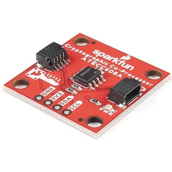
SparkFun Cryptographic Co-Processor Breakout - ATECC608A Qwiic
SPARKFUN¥1,498税込¥1,6481個33日以内出荷。Description。Product Restrictions:To access certain features of the ATECC608A, users will need to contact Microchip and sign an NDA contract to obtain the complete datasheet. Due to the required NDA - technical support, an Arduino library, and hookup guide are not provided for users on this product.。The SparkFun ATECC608A Cryptographic Co-processor Breakout allows you to add strong security to your IoT node, edge device, or embedded system. This includes。a。symmetric。authentication,。symmetric。AES-128 encryption/decryption, and much more. As stated above, the ATECC608A has limited Arduino support and the complete datasheet is under NDA with Microchip.。This breakout board includes two Qwiic ports for plug and play functionality. Utilizing our handy Qwiic system, no soldering is required to connect it to the rest of your system. However, we still have broken out 0.1"-spaced pins in case you prefer to use a breadboard. The ATECC608A chip is capable of many cryptographic processes, including, but not limited to:Creating and securely storing unique asymmetric key pairs based on Elliptic Curve Cryptography(FIPS186-3).。AES-128:Encrypt/Decrypt, Galois Field Multiply for GCM。Creating and verifying 64-byte digital signatures(from 32-bytes of message data).。Creating a shared secret key on a public channel via Elliptic Curve Diffie-Hellman Algorithm.。SHA-256 HMAC Hash including off-chip context save/restore。Internal high quality FIPS random number generator.。Embedded in the chip is a 10Kb EEPROM array that can be used for storing keys, certificates, data, consumption logging, and security configurations. Access to the sections of memory can then be restricted and the configuration locked to prevent changes. Each ATECC608A Breakout ships with a guaranteed unique 72-bit serial number and includes several security features to prevent physical attacks on the device itself, or logical attacks on the data transmitted between the device.。A summary datasheet for the ATECC608A is available here. The full datasheet is under NDA with Microchip. You will need to contact them for access to the entire datasheet. Meanwhile, the ArduinoATECCX08 Library currently only supports the ATECC608A with SAMD21 Arduino boards.。We do have much more support for the ATECC508A version of this chip. Please check out our ATECC508A Hookup Guide and Arduino Library(which includes six examples). This will get you familiar with the basics of elliptic curve cryptography and signing/verifying data with the ATECC508A version of the chip.。Note:The I2C address of the ATECC608A is 0x60 and is software-configurable to any address. A multiplexer/Mux is required to communicate to multiple ATECC608A sensors at the default address when on a single bus. If you need to use more than one ATECC608A sensor at the default address, consider using the Qwiic Mux Breakout.。Note:The ATECC608A can be only configured once before it is。PERMANENTLY。locked。. It is advisable that users purchase multiple boards in order to use other configurations and explore the advanced functions of the ATECC608A.。Additionally, this board。IS。capable of encrypting and decrypting data. However, to access these additional features, you will need to contact Microchip and sign an NDA contract to obtain the complete datasheet.。It is recommended that an SparkFun RedBoard Turbo - SAMD21 Development Board is used with this product due to the buffer size required on the I2C bus.。The SparkFun Qwiic Connect System is an ecosystem of I2C sensors, actuators, shields and cables that make prototyping faster and less prone to error. All Qwiic-enabled boards use a common 1mm pitch, 4-pin JST connector. This reduces the amount of required PCB space, and polarized connections mean you can't hook it up wrong.。。Features。Operating Voltage:2.0V-5.5V(。Default on Qwiic System:3.3V。)。Active Current Draw(for ATECC608A):16 mA。Sleep Current(for ATECC608A):<150 nA。Guaranteed Unique 72-bit Serial Number。10 Kb EEPROM Memory for Keys, Certificates, and Data。Storage for up to 16 Keys。256-bit Key Length。Internal High-Quality FIPS Random Number Generator(RNG)。Configurable I2C Address(7-bit):0x60(。Default。)アズワン品番67-0423-59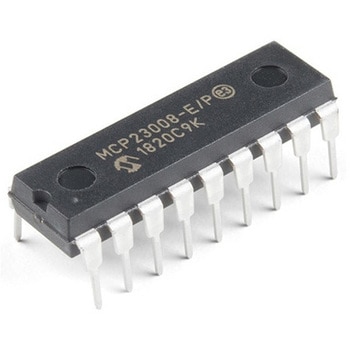
I/O Expander - MCP23008
SPARKFUN¥639税込¥7031個33日以内出荷。Description。Add another eight pins to your microcontroller using a MCP23008 port expander. The MCP23008 uses two I2C pins which can be shared with other I2C devices, and in exchange gives you eight general purpose pins. You can set each of eight pins to be input, output, or input with a pullup. There's even the ability to get an interrupt via an external pin when any of the inputs change so you don't have to keep polling the chip.。Use this chip from 2.7-5.5V(good for any 3.3V or 5V setup), and you can sink/source up to 20mA from any of the I/O pins so this will work for LEDs and such. Team it up with a high-power MOSFET if you need more juice. DIP package means it will plug into any breadboard or perfboard.。You can set the I2C address by tying the ADDR0-2 pins to power or ground, for up to eight unique addresses. That means eight chips can share a single I2C bus - that's 64 I/O pins!。Features。8-bit remote bidirectional I/O port。High-speed I2C interface(MCP23008)。Hardware address pins。Configurable interrupt output pin。Configurable interrupt source。Polarity Inversion register for input port data polarity config.。External reset input。Low standby current:1 μA(max.)・ Operating voltage:。1.8V to 5.5V @ -40℃ to +85℃ I2C @ 100 kHz SPI @ 5 MHz。2.7V to 5.5V @ -40℃ to +85℃ I2C @ 400 kHz SPI @ 10 MHz。4.5V to 5.5V @ -40℃ to +125℃ I2C @ 1.7 kHz SPI @ 10 MHzアズワン品番67-0421-32