カテゴリ
- 学童・教育用品(58)
- 制御機器(3)
絞り込み
ブランド
- SPARKFUN
- 富士電線工業(13)
- 三ツ星(5)
- WAKO'S(ワコーズ)(1)
- 堺電業(6)
- MICHELIN(ミシュラン)(3)
- BIGM(丸山製作所)(258)
- KOA(122)
- TE Connectivity Japan(旧:TYCOELECTRONICS(タイコエレクトロニクス))(121)
- オカムラ(岡村製作所)(82)
- 明工社(62)
- エスコ(48)
- Panasonic(パナソニック)(48)
- SMC(47)
- NSK(日本精工)(44)
- メディアカバーマーケット(44)
- ニッサン(43)
- セブンユニフォーム(34)
- azbil(旧:山武)(33)
- ブランドをもっと見る
「2ct」の検索結果
特価
 Zio Qwiic OLED Display 1.5inch, 128x128SPARKFUN
¥10,980税込¥12,078
1個
予約販売
DescriptionHere is the Zio Qwiic 1.5inch 128×128 pixels OLED display module. It can display a maximum of 16 lines of text content, and display pictures and animation on its 1.5-inch display. On the backside, there are two Qwiic connectors. With the Qwiic connect system no soldering is required to connect it to the rest of your system.Fit for use in small embedded systems, and also suitable for any projects that require displays of any kind, this screen is a must-have for Makers to include in even as one of their wearable DIY projects.The SparkFun Qwiic Connect System is an ecosystem of I2C sensors, actuators, shields and cables that make prototyping faster and less prone to error. All Qwiic-enabled boards use a common 1mm pitch, 4-pin JST connector. This reduces the amount of required PCB space, and polarized connections mean you can't hook it up wrong.FeaturesResolution:128×128 pixelsDisplay IC:SSD1327I2C address:0x78, 0x7A(Default:0x78)Display Color:White
アズワン品番67-0424-98
 SparkFun Qwiic Thermocouple Amplifier - MCP9600 Screw TerminalsSPARKFUN
¥7,998税込¥8,798
1個
予約販売
DescriptionThe MCP9600 Breakout is a high accuracy Thermocouple Amplifier equipped with an I2C interface, accessed over our Qwiic system. Inside the chip are two temperature sensors, one for the thermocouple itself(the hot junction)and one for the chip itself(the cold junction). As a result, the MCP9600 can read both the ambient temperature and the temperature of whatever you're trying to measure! The MCP9600 can do both with a resolution of 0.0625℃, and an accuracy of ±1.5℃(worst-case). The MCP9600 Thermocouple Amplifier is one of our many Qwiic compatible boards! Simply plug and go. No soldering, no figuring out which is SDA or SCL, and no voltage regulation or translation required!This version of the board comes equipped with screw terminals to allow for your own Thermocouple's wiring to be hooked up with the turn of a screw. This makes it perfect for a variety of applications, from measuring the temperature of your Crock-Pot to making sure your backyard induction furnace is up to temperature.In addition, the MCP9600 has four on-board temperature alerts that you can configure! Instead of constantly polling the sensor over I2C, you can set a temperature limit to trigger an interrupt when the temperature reaches a certain value. This frees up your microcontroller and your I2C bus to do more important things. It's also possible to put the MCP9600 into alternate operation modes in order to save power. The sensor supports a burst mode, where it will take a specified number of samples, return the results, and then go to sleep. This low-power mode makes the MCP9600 perfect for portable applications!We've written an Arduino library to help you get started quickly. You can download the library through the Arduino library manager by searching 'SparkFun MCP9600' or you can get the GitHub repo as a .zip file and install the library from there.The SparkFun Qwiic Connect System is an ecosystem of I2C sensors, actuators, shields and cables that make prototyping faster and less prone to error. All Qwiic-enabled boards use a common 1mm pitch, 4-pin JST connector. This reduces the amount of required PCB space, and polarized connections mean you can't hook it up wrong.Get Started with the Qwiic Thermocouple AmplifierFeaturesTemperature Range of -200℃ to 1350℃Four Onboard Temperature AlertsResolution of 0.0625℃Screw Terminal ConnectorADDR Jumper for variable I2C Addresses(default address of 0x60)2x Qwiic Connectors
アズワン品番67-0427-15
 SparkFun Qwiic HAT for Raspberry PiSPARKFUN
¥1,798税込¥1,978
1個
33日以内出荷
DescriptionThe SparkFun Qwiic HAT for Raspberry Pi is the quickest and easiest way to enter into SparkFun's Qwiic ecosystem while still using that Raspberry Pi that you've come to know and love. The Qwiic HAT connects the I2C bus(GND, 3.3V, SDA and SCL)on your Raspberry Pi to an array of Qwiic connectors on the HAT. Since the Qwiic system allows for daisy chaining boards with different addresses, you can stack as many sensors as you'd like to create a tower of sensing power!The Qwiic Pi HAT has four Qwiic connect ports, all on the same I2C bus. In addition, many of the useful GPIO pins on the Raspberry Pi are broken out. This HAT is compatible with any Raspberry Pi that utilizes the standard 2x20 GPIO header. It has been designed to sit to the side of the Pi, allowing it to work conveniently with a Pi Tin enclosure to connect boards to the Qwiic ports.Note:There is a small silk error that has reversed the SDA and SCL. This is simply a cosmetic mix-up and will not impact any function with this board.The SparkFun Qwiic Connect System is an ecosystem of I2C sensors, actuators, shields and cables that make prototyping faster and less prone to error. All Qwiic-enabled boards use a common 1mm pitch, 4-pin JST connector. This reduces the amount of required PCB space, and polarized connections mean you can't hook it up wrong.Get Started with the SparkFun Qwiic Pi HAT GuideFeatures4x Qwiic Connection PortsSelect GPIO Pins Broken OutPi Tin Compatibility
アズワン品番67-0422-50
 SparkFun Qwiic Dual Solid State RelaySPARKFUN
¥39,980税込¥43,978
1個
33日以内出荷
DescriptionThe SparkFun Qwiic Dual Solid State Relay is a power delivery board that allows users to switch two AC loads from a low power microcontroller using the SparkFun Qwiic connect system. The board features two 25A/250VAC solid state relays that utilize the Zero Cross Trigger method so you can toggle two loads on a 60Hz AC carrier signal on and off up to 120 times per second!An ATTiny84 acts as the "brain" of the SparkFun Qwiic Dual Solid Relay to accept I2C commands to toggle the two relays as well as a few other special commands. The I2C address of the ATtiny84A is software configurable so, if you have a seriously big power project in mind, you could daisy chain over 100 Qwiic Dual Solid State Relays.Messing with such high voltage is dangerous! We've included many safety precautions onto the PCB including ground isolation between the relay and other circuitry and a milled out area isolating each side of AC. However, with all the safety precautions included with the SparkFun Qwiic Dual Solid State Relay, this is still a power accessory for users who are experienced around, and knowledgeable about high AC voltage. If you're not comfortable with handling AC voltage in this way, you may want to check out the IoT Power Relay instead.Note:The relays are rated for a max of 25A with forced air cooling. If you do not have forced air cooling, 10A max through the relays is recommended.The SparkFun Qwiic connect system is an ecosystem of I2C sensors, actuators, shields and cables that make prototyping faster and less prone to error. All Qwiic-enabled boards use a common 1mm pitch, 4-pin JST connector. This reduces the amount of required PCB space, and polarized connections mean you can't hook it up wrong.Get Started with the SparkFun Qwiic Dual Solid State Relay GuideFeaturesOperating Voltage:2.5-3.6V(3.3V recommended)I2C Address:0x0A(Default)0x0B(Alternate via jumper select)Load Voltage Range:12-280VACMax Current(Through Relay):25A(240VAC with forced air cooling)Zero Cross TriggerNormally Open Circuit Only2x Qwiic Connector
アズワン品番67-0421-58
 SparkFun Qwiic AdapterSPARKFUN
¥429税込¥472
1個
33日以内出荷
DescriptionThe SparkFun Qwiic Adapter provides the perfect means to make any old I2C board into a Qwiic-enabled board. This adapter breaks out the I2C pins from the Qwiic connectors to pins that you can easily solder with your favorite I2C-enabled device.The Qwiic Adapter has two Qwiic connection ports, all on the same I2C bus. Four plated through holes are broken out for SCL, SDA, 3.3V and GND. These pins can be used to convert an old I2C-enabled device into a Qwiic-enabled board.The SparkFun Qwiic Connect System is an ecosystem of I2C sensors, actuators, shields and cables that make prototyping faster and less prone to error. All Qwiic-enabled boards use a common 1mm pitch, 4-pin JST connector. This reduces the amount of required PCB space, and polarized connections mean you can't hook it up wrong.Get Started with the SparkFun Qwiic Adapter GuideFeatures2x Qwiic Connection PortsBroken-out I2C Pins
アズワン品番67-0419-69
 SparkFun MicroMod Data Logging Carrier BoardSPARKFUN
¥4,998税込¥5,498
1個
33日以内出荷
DescriptionThe SparkFun MicroMod Data Logging Board offers a highly customizable, low-power data logging platform using the MicroMod system allowing you to choose your own Processor to pair with the Carrier Board. The Data Logging Carrier Board breaks out connections for I2C via a Qwiic connector or standard 0.1"-spaced PTH pins along with SPI and serial UART connections for logging data from peripheral devices using those communication protocols.The Data Logging Carrier Board allows you to control power to both the Qwiic connector on the board and a dedicated 3.3V power rail for non-Qwiic peripherals so you can pick and choose when to power the peripherals you are monitoring the data from. It also features a charging circuit for single-cell Lithium-ion batteries along with a separate RTC battery-backup circuit to maintain power to a real-time clock circuit on your Processor Board.MicroMod is a modular interface ecosystem that connects a microcontroller "processor board" to various "carrier board" peripherals. Utilizing the M.2 standard, the MicroMod standard is designed to easily swap out processors on the fly. Pair a specialized carrier board for the project you need with your choice of compatible processor!Get Started with the MicroMod Data Logging Carrier Board GuideFeaturesM.2 MicroMod ConnectormicroSD socketUSB-C Connector3.3V 1A Voltage RegulatorQwiic ConnectorBoot/Reset ButtonsRTC Backup Battery Charge CircuitIndependent 3.3V regulators for Qwiic bus and peripheral add-onsControlled by digital pins on Processor Board to enable low power sleep modesPhillips #0 M2.5x3mm screw included
アズワン品番67-0423-16
 SparkFun MicroMod Artemis ProcessorSPARKFUN
¥5,598税込¥6,158
1個
33日以内出荷
DescriptionLeveraging the ultra powerful Artemis Module, the SparkFun MicroMod Artemis Processor is the brain board of your dreams. With a Cortex-M4F with BLE 5.0 running up to 96MHz and with as low power as 6uA per MHz(less than 5mW), the M.2 MicroMod connector allows you to plug in a MicroMod Carrier Board with any number of peripherals. Let's have a look at what this processor board has to offer! If you need Machine Learning capabilities, Bluetooth, I2C functionality to connect to all our amazing Qwiic boards, and more the Artemis Processor is the perfect choice for your MicroMod Carrier Board.At the heart of SparkFun's Artemis Module is Ambiq Micro's Apollo3 processor, whose ultra-efficient ARM Cortex-M4F processor is spec'd to run TensorFlow Lite using only 6uA/MHz. We've routed two I2C buses, eight GPIO, dedicated digital, analog, and PWM pins, multiple SPI as well as QuadSPI, and Bluetooth to boot. You really can't go wrong with this processor. Grab one today, pick up a compatible carrier board, and get hacking!MicroMod is a modular interface ecosystem that connects a microcontroller "processor board" to various "carrier board" peripherals. Utilizing the M.2 standard, the MicroMod standard is designed to easily swap out processors on the fly. Pair a specialized carrier board for the project you need with your choice of compatible processor!Get Started with the MicroMod Artemis Processor GuideFeaturesArtemis General Features1M Flash / 384k RAM48MHz / 96MHz turbo available6uA/MHz(operates less than 5mW at full operation)48 GPIO - all interrupt capable31 PWM channelsBuilt in BLE radio and antenna10 ADC channels with 14-bit precision with up to 2.67 million samples per second effective continuous, multi-slot sampling rate2 channel differential ADC2 UARTs6 I2C buses6 SPI buses2/4/8-bit SPI busPDM interfaceI2S InterfaceSecure 'Smart Card' interfaceFCC/IC/CE Certified(ID Number 2ASW8-ART3MIS)Specific Peripherals made available on MicroMod Artemis:1x USB dedicated for programming and debug1x UART with flow control2x I2C1x SPI1x Quad-SPI8x Fast GPIO2x Digital Pins2x Analog Pins2x PWM1x Differential ADC pairStatus LEDVIN Level ADCAdditional peripherals are available but are shared on dedicated MicroMod pins.
アズワン品番67-0423-05
 SparkFun GPS Breakout - NEO-M9N, SMA QwiicSPARKFUN
¥19,980税込¥21,978
1個
33日以内出荷
DescriptionThe SparkFun NEO-M9N GPS Breakout is a high quality GPS board with equally impressive configuration options including SMA. The NEO-M9N module is a 92-channel u-blox M9 engine GNSS receiver, meaning it can receive signals from the GPS, GLONASS, Galileo, and BeiDou constellations with ~1.5 meter accuracy. This breakout supports concurrent reception of four GNSS. This maximizes position accuracy in challenging conditions increasing, precision and decreases lock time; and thanks to the onboard rechargeable battery, you'll have backup power enabling the GPS to get a hot lock within seconds! Additionally, this u-blox receiver supports I2C(u-blox calls this Display Data Channel)which makes it perfect for the Qwiic compatibility so we don't have to use up our precious UART ports. Utilizing our handy Qwiic system, no soldering is required to connect it to the rest of your system. However, we still have broken out 0.1"-spaced pins in case you prefer to use a breadboard.The NEO-M9N module detects jamming and spoofing events and can report them to the host, so that the system can react to such events. A SAW(Surface Acoustic Wave)filter combined with an LNA(Low Noise Amplifier)in the RF path is integrated into the NEO-M9N module which allows normal operation even under strong RF interferences.U-blox based GPS products are configurable using the popular, but dense, windows program called u-center. Plenty of different functions can be configured on the NEO-M9N:baud rates, update rates, geofencing, spoofing detection, external interrupts, SBAS/D-GPS, etc. All of this can be done within the SparkFun Arduino Library!The SparkFun NEO-M9N GPS Breakout is also equipped with an on-board rechargeable battery that provides power to the RTC on the NEO-M9N. This reduces the time-to-first fix from a cold start(~24s)to a hot start(~2s). The battery will maintain RTC and GNSS orbit data without being connected to power for plenty of time.This product requires an antenna:Be sure to check out the related products/hookup accessories and pick a suitable SMA antenna for your project.The SparkFun Qwiic Connect System is an ecosystem of I2C sensors, actuators, shields and cables that make prototyping faster and less prone to error. All Qwiic-enabled boards use a common 1mm pitch, 4-pin JST connector. This reduces the amount of required PCB space, and polarized connections mean you can't hook it up wrong.The NEO-M9N GPS Breakout can also be automatically detected, scanned, configured, and logged using the OpenLog Artemis datalogger system. No programming, soldering, or setup required!Get Started With the SparkFun NEO-M9N GPS GuideFeaturesIntegrated SMA connector for use with antenna of your choice92-Channel GNSS Receiver1.5m Horizontal Accuracy25Hz Max Update Rate(four concurrent GNSS)Time-To-First-Fix:Cold:24sHot:2sMax Altitude:80,000mMax G:≦4Max Velocity:500m/sVelocity Accuracy:0.05m/sHeading Accuracy:0.3 degreesTime Pulse Accuracy:30ns3.3V VCC and I/OCurrent Consumption:~31mA Tracking GPS+GLONASSSoftware ConfigurableGeofencingOdometerSpoofing DetectionExternal InterruptPin ControlLow Power ModeMany others!Supports NMEA, UBX, and RTCM protocols over UART or I2C interfaces
アズワン品番67-0423-87
 SparkFun Atmospheric Sensor Breakout - BME280SPARKFUN
¥6,898税込¥7,588
1個
33日以内出荷
DescriptionThe SparkFun BME280 Atmospheric Sensor Breakout is the easy way to measure barometric pressure, humidity, and temperature readings all without taking up too much space. Basically, anything you need to know about atmospheric conditions you can find out from this tiny breakout. The BME280 Breakout has been design to be used in indoor/outdoor navigation, weather forecasting, home automation, and even personal health and wellness monitoring.The on-board BME280 sensor measures atmospheric pressure from 30kPa to 110kPa as well as relative humidity and temperature. The breakout provides a 3.3V SPI interface, a 5V tolerant I2C interface(with pull-up resistors to 3.3V), takes measurements at less than 1mA and idles less than 5μA. The BME280 Breakout board has 10 pins, but no more than six are used at a single time. The left side of the board provide power, ground, and I2C pins. The remaining pins which provide SPI functionality and have another power and ground, are broken out on the other side.Note:The breakout does NOT have headers installed and will need to purchased and soldered on yourself. Check theRecommended Productssection below for the type of headers we use in the Hookup Guide!FeaturesOperation Voltage:3.3VI2C SPI Communications InterfaceTemp Range:-40C to 85CHumidity Range:0 - 100% RH, =-3% from 20-80%Pressure Range:30,000Pa to 110,000Pa, relative accuracy of 12Pa, absolute accuracy of 100PaAltitude Range:0 to 30,000 ft(9.2 km), relative accuracy of 3.3 ft(1 m)at sea level, 6.6(2 m)at 30,000 ft.Incredibly Small
アズワン品番67-0426-57
 Flexible Qwiic Cable - 200mmSPARKFUN
¥649税込¥714
1個
33日以内出荷
DescriptionThis is a 200mm long 4-conductor cable with 1mm JST termination. It's designed to connect Qwiic enabled components together but can be used for other applications as well. The cable insulation is made from a highly malleable material making it more flexible than our original Qwiic cable particularly in tight spaces or enclosures.Each Qwiic Cable's wires have been color coded to red, black, blue and yellow.The SparkFun Qwiic connect system is an ecosystem of I2C sensors, actuators, shields and cables that make prototyping faster and less prone to error. All Qwiic-enabled boards use a common 1mm pitch, 4-pin JST connector. This reduces the amount of required PCB space, and polarized connections mean you can't hook it up wrong.FeaturesDimensions:200mm(7.87")Length
アズワン品番67-0426-04
 Basic 16x2 Character LCD - Black on Green 5VSPARKFUN
¥5,998税込¥6,598
1個
33日以内出荷
仕様●種別:LCD(キャラクター)アズワン品番67-0453-89
 SparkFun Qwiic Alphanumeric Display - COMシリーズSPARKFUN
¥2,298税込¥2,528
1個
33日以内出荷
DescriptionThe SparkFun Alphanumeric Display Arduino library makes printing strings to the display as easy as calling the print()function. With this library, you'll be able to send I2C commands to the VK16K33 LED driver chip to light up segments(including the decimal point or colon)and even scroll your string across the display. You can download the library through the Arduino library manager by searching 'SparkFun Alphanumeric Display' or you can get the GitHub repo as a .zip file and install the library from there.The SparkFun Qwiic Connect System is an ecosystem of I2C sensors, actuators, shields and cables that make prototyping faster and less prone to error. All Qwiic-enabled boards use a common 1mm pitch, 4-pin JST connector. This reduces the amount of required PCB space, and polarized connections mean you can't hook it up wrong.Get Started with the Qwiic Alphanumeric Display Hookup GuideFeaturesOperating Voltage:3.3VIntegrated RC oscillatorMaximum display segment numbers:128 patterns13×3 matrix key scan circuit16-step dimming circuitI2C Addresses:0x70(0x71, 0x72, 0x73)2x Qwiic connectors2x Wall Mounting Points
アズワン品番67-0421-62
 SparkFun weather:bit - micro:bit Carrier Board QwiicSPARKFUN
¥5,398税込¥5,938
1個
33日以内出荷
DescriptionThe SparkFun weather:bit is a fully loaded "carrier" board for the micro:bit that, when combined with the micro:bit, provides you with a fully functional weather station. With the weather:bit you will have access to barometric pressure, relative humidity and temperature readings. There are also connections on this carrier board to optional sensors such as wind speed, direction, rain gauge and soil readings! In this version we have also added a vertical Qwiic connector. The micro:bit has a lot of features and a lot of potential for weather data collection.The weather:bit connects to the micro:bit via an edge connector at the top of the board, making setup easy. This creates a handy way to swap out micro:bits for programming, while still providing reliable connections to all of the different pins on the micro:bit. We have also included serial and I2C headers on the weather:bit for optimized connectivity if you so choose.The micro:bit is a pocket-sized computer that lets you get creative with digital technology. Between the micro:bit and our shield-like bit boards you can do almost anything while coding, customizing and controlling your micro:bit from almost anywhere! You can use your micro:bit for all sorts of unique creations, from robots to musical instruments and more. At half the size of a credit card, this versatile board has vast potential!Note:The SparkFun weather:bit doesNOTinclude a micro:bit board. The micro:bit will need to be purchased separately.Get started with the weather:bit GuideFeaturesOnboard temperature, humidity, and pressure sensorConnectors(PTH and screw terminal)for soil moisture and soil temperatureConnectors(RJ11)for wind speed, direction and rainfall gaugesEdge connector for easy micro:bit integrationVertical Qwiic connectorHeaders for Serial and I2C communication
アズワン品番67-0422-94
 SparkFun Thing Plus - RP2040SPARKFUN
¥6,698税込¥7,368
1個
33日以内出荷
DescriptionThe SparkFun Thing Plus - RP2040 is a low-cost, high performance board with flexible digital interfaces featuring the Raspberry Pi Foundation's RP2040 microcontroller. Besides the Thing Plus orFeatherfootprint(with 18 GPIO pins), the board also includes an SD card slot, 16MB(128Mbit)flash memory, a JST single cell battery connector(with a charging circuit and fuel gauge sensor), an addressable WS2812 RGB LED, JTAG PTH pins, four(4-40 screw)mounting holes, and our signature Qwiic connector.The RP2040 contains two ARM Cortex-M0+ processors(up to 133MHz)and features:264kB of embedded SRAM in six banks6 dedicated IO for SPI Flash(supporting XIP)30 multifunction GPIO:Dedicated hardware for commonly used peripheralsProgrammable IO for extended peripheral supportFour 12-bit ADC channels with internal temperature sensor(up to 0.5 MSa/s)USB 1.1 Host/Device functionalityThe RP2040 is supported with both C/C++ and MicroPython cross-platform development environments, including easy access to runtime debugging. It has UF2 boot and floating-point routines baked into the chip. While the chip has a large amount of internal RAM, the board includes an additional 16MB of external QSPI flash memory to store program code.The SparkFun Qwiic Connect System is an ecosystem of I2C sensors, actuators, shields and cables that make prototyping faster and less prone to error. All Qwiic-enabled boards use a common 1mm pitch, 4-pin JST connector. This reduces the amount of required PCB space, and polarized connections mean you can't hook it up wrong.Get Started With the Thing Plus RP2040 Hookup GuideFeaturesSparkFun Thing Plus - RP2040 FeaturesRaspberry Pi Foundation's RP2040 microcontroller16MB QSPI Flash MemoryJTAG PTH PinsThing Plus(or Feather)Form-Factor:18[1]x Multifunctional GPIO Pins[2]Four available 12-bit ADC channels with internal temperature sensor(500kSa/s)Up to eight 2-channel PWMUp to two UARTsUp to two I2C busesUp to two SPI busesUSB-C Connector:USB 1.1 Host/Device functionality2-pin JST Connector for a LiPo Battery(not included)500mA charging circuitQwiic ConnectorButtons:BootResetLEDs:PWR- Red 3.3V power indicatorCHG- Yellow battery charging indicator25- Blue status/test LED(GPIO 25)WS2812- Addressable RGB LED(GPIO 08)Four Mounting Holes:4-40 screw compatibleDimensions:2.3"×0.9"RP2040 General FeaturesDual Cortex M0+ processors, up to 133 MHz264 kB of embedded SRAM in 6 banks6 dedicated IO for QSPI flash, supporting execute in place(XIP)30 programmable IO for extended peripheral supportSWD interfaceTimer with 4 alarmsReal time counter(RTC)USB 1.1 Host/Device functionalitySupported programming languagesMicroPythonC/C++1.Note:GPIO 08is not included in this count, as it passes through the WS2812 addressable RGB LED first.GPIO 07andGPIO 23are counted as a single GPIO because they are tied together.2.Note:The GPIO pins are programmable so you can reconfigure the pins! Check out the RP2040 datasheet for more information on the GPIO functionality.
アズワン品番67-0423-56
 SparkFun Qwiic micro:bit BreakoutSPARKFUN
¥1,698税込¥1,868
1個
33日以内出荷
DescriptionThe SparkFun Qwiic micro:bit Breakout is a board that connects to the BBC micro:bit and expands the capabilities of the development platform by providing access to more pins and allowing for connections to the I2C and SPI buses. This breakout board for the micro:bit's edge connector allows intermediate and advanced users to connect the micro:bit to breadboards and other Qwiic sensors, motors, LEDs and more.The micro:bit on its own has three digital/analog input/output rings available for you to use initially with alligator clips. With the micro:bit Breakout we have broken out all 21 GPIO, power and ground-to-pin outs in a 0.1" formation and with two individual Qwiic Connectors. With this breakout you will be able to unlock the full potential of your micro:bit!Note:No micro:bit or headers are included with this breakout; they will need to be purchased separately. If you would like a micro:bit breakout with headers already soldered on, be sure to check out this board's sibling.The SparkFun Qwiic Connect System is an ecosystem of I2C sensors, actuators, shields and cables that make prototyping faster and less prone to error. All Qwiic-enabled boards use a common 1mm pitch, 4-pin JST connector. This reduces the amount of required PCB space, and polarized connections mean you can't hook it up wrong.Get Started with the Qwiic micro:bit Breakout Guide
アズワン品番67-0420-12
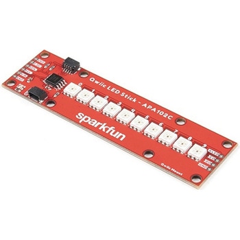 SparkFun Qwiic LED Stick - APA102CSPARKFUN
¥2,998税込¥3,298
1個
33日以内出荷
DescriptionThe SparkFun Qwiic LED Stick features ten addressable APA102 LEDs, making it easy to add full color LED control using I2C. Write to individual LEDs to display a count in binary, or write to the whole strip for cool lighting effects. You can even add more LEDs to the end if you need to. We've written an Arduino library and Python package that take care of the I2C and communication to the LEDs so all you have to do is decide what color each LED should be.The LED Stick has a default I2C address of 0x23 but can be changed with a simple command, allowing you to control up to 100 LEDs(10 Qwiic LED Sticks)on a single bus! The address can also be changed to 0x22 by closing the solder jumper on the back of the board.This board is one of our many Qwiic compatible boards! Simply plug and go. No soldering, no figuring out which is SDA or SCL, and no voltage regulation or translation required!Warning:Using a lot of LEDs can draw a lot of current. Make sure to consider the power limits of your setup. If you expect your LED chain to draw more than 600mA of current, connect your external supply directly to VLED. Closing the jumper from VLED to VCC will add a 4.7uF decoupling capacitor.The SparkFun Qwiic Connect System is an ecosystem of I2C sensors, actuators, shields and cables that make prototyping faster and less prone to error. All Qwiic-enabled boards use a common 1mm pitch, 4-pin JST connector. This reduces the amount of required PCB space, and polarized connections mean you can't hook it up wrong.Get Started with the Qwiic LED Stick GuideFeatures10x APA102C addressable LEDs driven by an ATTiny85Default I2C Address:0x23(Adjustable to 0x22 via Jumper)2x Qwiic Connectors
アズワン品番67-0421-83
 SparkFun Qwiic Alphanumeric Display - WhiteSPARKFUN
¥2,298税込¥2,528
1個
33日以内出荷
DescriptionWe are quite familiar with seven-segment displays. We see them on our alarm clocks, ovens, and microwaves. By adding more segments to each digit you can display more than just numbers! Introducing the brand new SparkFun Qwiic Alphanumeric Display. These white fourteen-segment digits allow you display all sorts of numbers, characters, and symbols. With Qwiic, simply plug it in and go. No soldering, no figuring out which is SDA or SCL, and no voltage regulation or translation required!The SparkFun Alphanumeric Display Arduino library makes printing strings to the display as easy as calling the print()function. With this library, you'll be able to send I2C commands to the VK16K33 LED driver chip to light up segments(including the decimal point or colon)and even scroll your string across the display. You can download the library through the Arduino library manager by searching 'SparkFun Alphanumeric Display' or you can get the GitHub repo as a .zip file and install the library from there.The VK16K33 also supports I2C address configuration. Simply close a combination of the address jumpers on the back and you can communicate with up to four displays on the same bus. Our slim board design also features detachable stand off holes, vertical Qwiic connectors, and internal mounting holes.The SparkFun Qwiic Connect System is an ecosystem of I2C sensors, actuators, shields and cables that make prototyping faster and less prone to error. All Qwiic-enabled boards use a common 1mm pitch, 4-pin JST connector. This reduces the amount of required PCB space, and polarized connections mean you can't hook it up wrong.Get Started with the Qwiic Alphanumeric Display Hookup GuideFeaturesWhite displayOperating Voltage:3.3VIntegrated RC oscillatorMaximum display segment numbers:128 patterns13×3 matrix key scan circuit16-step dimming circuitI2C Addresses:0x70(0x71, 0x72, 0x73)2x Qwiic connectors2x Wall Mounting Points
アズワン品番67-0421-87
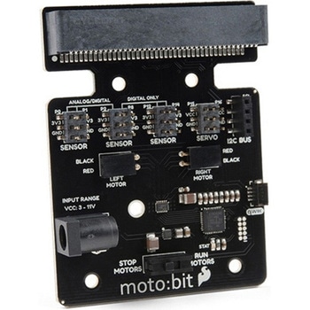 SparkFun moto:bit - micro:bit Carrier Board QwiicSPARKFUN
¥8,498税込¥9,348
1個
33日以内出荷
DescriptionThe SparkFun moto:bit is a fully loaded "carrier" board for the micro:bit that, when combined with the micro:bit, provides you with a fully functional robotics platform. The moto:bit offers a simple, beginner-friendly robotics controller capable of operating a basic robotics chassis. Onboard each moto:bit are multiple I/O pins, as well as a vertical Qwiic connector, capable of hooking up servos, sensors and other circuits. At the flip of the switch you can get your micro:bit moving!The moto:bit connects to the micro:bit via an updated SMD, edge connector at the top of the board, making setup easy. This creates a handy way to swap out micro:bits for programming, while still providing reliable connections to all of the different pins on the micro:bit. We have also included a basic barrel jack on the moto:bit that is capable of providing power to anything you connect to the carrier board.The micro:bit is a pocket-sized computer that lets you get creative with digital technology. Between the micro:bit and our shield-like bit boards you can do almost anything while coding, customizing and controlling your micro:bit from almost anywhere! You can use your micro:bit for all sorts of unique creations, from robots to musical instruments and more. At half the size of a credit card, this versatile board has vast potential!Note:The SparkFun moto:bit doesNOTinclude a micro:bit board. The micro:bit will need to be purchased separately.Get started with the moto:bit GuideFeaturesMore reliable Edge connector for easy use with the micro:bitFull H-Bridge for control of two motorsControl servo motorsVertical Qwiic ConnectorI2C port for extending functionalityPower and battery management onboard for the micro:bit
アズワン品番67-0422-89
 SparkFun Basic 16x2 Character LCD - White on Black, 5V with HeadersSPARKFUN
¥6,498税込¥7,148
1個
予約販売
DescriptionThis is a basic 16 character by two line display with a snazzy black background with white characters. This LCD utilizes the extremely common HD44780 parallel interface chipset. Interface code is freely available. This is the same LCD that is included with the SparkFun Inventor's Kit and comes with all the GPIO pins pre-soldered on for quick and easy interfacing.Includes white LED backlight.Get Started with the Basic Character LCD GuideFeatures3.15"×1.425"
アズワン品番67-0425-06
 QWIIC 12BIT 4CHANNEL ADS1015SPARKFUN
¥5,198税込¥5,718
1個
予約販売
DescriptionA lot of the time you just need to add more analog inputs to solve a problem. It happens. The SparkFun Qwiic 12 Bit ADC can provide four channels of I2C controlled ADC input to your Qwiic enabled project. These channels can be used as single-ended inputs, or in pairs for differential inputs. What makes this even more powerful is that it has a programmable gain amplifier that lets you "zoom in" on a very small change in analog voltage(but will still effect your input range and resolution). Utilizing our handy Qwiic system, no soldering is required to connect it to the rest of your system. However, we still have broken out 0.1"-spaced pins in case you prefer to use a breadboard.The ADS1015 uses its own internal voltage reference for measurements, but a ground and 3.3V reference are also available on the pin outs for users. This ADC board includes screw pin terminals on the four channels of input, allowing for solderless connection to voltage sources in your setup. It also has an address jumper that lets you choose one of four unique addresses(0x48, 0x49, 0x4A, 0x4B). With this, you can connect up to four of these on the same I2C bus and have sixteen channels of ADC. The maximum resolution of the converter is 12-bits in differential mode and 11-bits for single-ended inputs. Step sizes range from 125μV per count to 3mV per count depending on the full-scale range(FSR)setting.We have included an onboard 10K trimpot connected to channel A3. This is handy for initial setup testing and can be used as a simple variable input to your project. But don't worry, we added an isolation jumper so you can use channel A3 however you'd like.Note:The I2C address of the ADS1015 is 0x48 and is jumper selectable to 0x49, 0x4A, 0x4B. A multiplexer/Mux is required to communicate to multiple ADS1015 sensors on a single bus. If you need to use more than one ADS1015 sensor consider using the Qwiic Mux Breakout.The SparkFun Qwiic connect system is an ecosystem of I2C sensors, actuators, shields and cables that make prototyping faster and less prone to error. All Qwiic-enabled boards use a common 1mm pitch, 4-pin JST connector. This reduces the amount of required PCB space, and polarized connections mean you can't hook it up wrong.Get Started with the SparkFun Qwiic 12-Bit ADC Hookup GuideFeaturesADS1015Operating Voltage(VDD):2.0V-5.5V(Note:When powering with a Qwiic cable, the input range is only 3.3v)Operating Temperature:-40℃ to 125℃Operation Modes:Single-Shot, Continuous-Conversion(Default), and Duty CyclingAnalog Inputs:Measurement Type:Single-Ended(Default)Input Voltage Range:GND to VDDFull Scale Range(FSR):±.256V to ±6.114V(Default:2.048V)Resolution:12-bit(Differential)or 11-bit(Single-Ended)LSB size:0.125mV - 3mV(Default:1 mV)Sample Rate:128 Hz to 3.3 kHz(Default:1600SPS)Current Consumption(Typical):150μA-200μAI2C Address:0x48(Default), 0x49, 0x4A, or 0x4BScrew pin terminals for solderless connection to voltage sourcesFour unique I2C addresses:0x480x490x4A0x4B2x Qwiic connection portsOnboard 10K trimpot
アズワン品番67-0360-13
 Flexible Qwiic Cable - 100mmSPARKFUN
¥619税込¥681
1個
33日以内出荷
DescriptionThis is a 100mm long 4-conductor cable with 1mm JST termination. It's designed to connect Qwiic enabled components together but can be used for other applications as well. The cable insulation is made from a highly malleable material making it more flexible than our original Qwiic cable particularly in tight spaces or enclosures.Each Qwiic Cable's wires have been color coded to red, black, blue and yellow.The SparkFun Qwiic connect system is an ecosystem of I2C sensors, actuators, shields and cables that make prototyping faster and less prone to error. All Qwiic-enabled boards use a common 1mm pitch, 4-pin JST connector. This reduces the amount of required PCB space, and polarized connections mean you can't hook it up wrong.FeaturesDimensions:100mm(3.93")Length
アズワン品番67-0426-05
 SparkFun Qwiic Alphanumeric Display - COMシリーズSPARKFUN
¥2,398税込¥2,638
1個
33日以内出荷
DescriptionThe SparkFun Alphanumeric Display Arduino library makes printing strings to the display as easy as calling the print()function. With this library, you'll be able to send I2C commands to the VK16K33 LED driver chip to light up segments(including the decimal point or colon)and even scroll your string across the display. You can download the library through the Arduino library manager by searching 'SparkFun Alphanumeric Display' or you can get the GitHub repo as a .zip file and install the library from there.The SparkFun Qwiic Connect System is an ecosystem of I2C sensors, actuators, shields and cables that make prototyping faster and less prone to error. All Qwiic-enabled boards use a common 1mm pitch, 4-pin JST connector. This reduces the amount of required PCB space, and polarized connections mean you can't hook it up wrong.Get Started with the Qwiic Alphanumeric Display Hookup GuideFeaturesOperating Voltage:3.3VIntegrated RC oscillatorMaximum display segment numbers:128 patterns13×3 matrix key scan circuit16-step dimming circuitI2C Addresses:0x70(0x71, 0x72, 0x73)2x Qwiic connectors2x Wall Mounting Points
アズワン品番67-0421-64
 SparkFun Qwiic Keypad - 12 ButtonSPARKFUN
¥3,598税込¥3,958
1個
33日以内出荷
DescriptionKeypads are very handy input devices, but who wants to tie up seven GPIO pins, wire up handful of pull-up resistors, and write firmware that wastes valuable processing time scanning the keys for inputs? The SparkFun Qwiic Keypad comes fully assembled and makes the development process for adding 12 button keypad easy. No voltage translation or figuring out which I2C pin is SDA or SCL, just plug and go! Utilizing our handy Qwiic system, no soldering is required to connect it to the rest of your system. However, we still have broken out 0.1"-spaced pins in case you prefer to use breadboard.Each of the keypad's 12 buttons has been labeled 1, 2, 3, 4, 5, 6, 7, 8, 9, 0, *, and and has been formatted to into the same layout as telephone keypad with each keypress resistance ranging between 10 and 150 Ohms. The Qwiic Keypad reads and stores the last 15 button presses in First-In, First-Out(FIFO)stack, so you don't need to constantly poll the keypad from your microcontroller. This information, then, is accessible through the Qwiic interface. The SparkFun Qwiic Keypad even has software configurable I2C address so you can have multiple I2C devices on the same bus.NOTE:The I2C address of the Qwiic Keypad is 0x4B and is jumper selectable to 0x4A(software-configurable to any address). multiplexer/Mux is required to communicate to multiple Qwiic Keypad sensors on single bus. If you need to use more than one Qwiic Keypad sensor consider using the Qwiic Mux Breakout.The SparkFun Qwiic connect system is an ecosystem of I2C sensors, actuators, shields and cables that make prototyping faster and less prone to error. All Qwiic-enabled boards use common 1mm pitch, 4-pin JST connector. This reduces the amount of required PCB space, and polarized connections mean you can't hook it up wrong.Get Started with the SparkFun Qwiic Keypad Hookup GuideFeaturesSoftware Selectable Slave AddressLow Power ATtiny85 controllerButton Presses w/ Time StampDefault I2C Address:0x4B2x Qwiic Connector
アズワン品番67-0421-41
 SparkFun IR Array Breakout - 55 Degree FOV, MLX90640 QwiicSPARKFUN
¥19,980税込¥21,978
1個
33日以内出荷
DescriptionIt's time to say hip hip array for this IR Breakout! The MLX90640 SparkFun IR Array Breakout is equipped with a 32x24 array of thermopile sensors creating, in essence, a low resolution thermal imaging camera. With this breakout you can detect surface temperatures from many feet away with an accuracy of ±1.5℃(best case). To make it even easier to get your infrared image, all communication is enacted exclusively via I2C, utilizing our handy Qwiic system. However, we still have broken out 0.1"-spaced pins in case you prefer to use a breadboard.This specific IR Array Breakout features a55°x35°field of view with a temperature measurement range of -40℃-300℃. The MLX90640 IR Array has pull up resistors attached to the I2C bus; both can be removed by cutting the traces on the corresponding jumpers on the back of the board. Please be aware that the MLX90640 requires complex calculations by the host platform so a regular Arduino Uno(or equivalent)doesn't have enough RAM or flash to complete the complex computations required to turn the raw pixel data into temperature data. You will need a microcontroller with 20,000 bytes or more of RAM. To achieve this, we recommend a Teensy 3.1 or above.The SparkFun Qwiic connect system is an ecosystem of I2C sensors, actuators, shields and cables that make prototyping faster and less prone to error. All Qwiic-enabled boards use a common 1mm pitch, 4-pin JST connector. This reduces the amount of required PCB space, and polarized connections mean you can't hook it up wrong.Get Started with the SparkFun IR Array Breakout GuideFeaturesOperating Voltage:3V-3.6VCurrent Consumption:~18mAField of View:55°x35°Measurement Range:-40℃-300℃Resolution:±1.5℃Refresh Rate:0.5Hz-64HzI2C Address:0x332x Qwiic Connection Ports
アズワン品番67-0426-88
 SparkFun Servo pHAT for Raspberry PiSPARKFUN
¥3,898税込¥4,288
1個
33日以内出荷
DescriptionThe SparkFun Servo pHAT for Raspberry Pi allows your Raspberry Pi to control up to 16 servo motors in a straightforward and uncomplicated manner via an I2C connection. Thanks to its I2C capabilities, this PWM HAT saves the Raspberry Pi's GP
アズワン品番67-0422-77
 SparkFun Qwiic OpenLogSPARKFUN
¥5,798税込¥6,378
1個
33日以内出荷
DescriptionThe SparkFun Qwiic OpenLog is the smarter and better looking cousin to the extremely popular OpenLog but now we've ported the original serial based interface to I2C! Thanks to the added Qwiic connectors, you can daisy chain multiple I2C dev
アズワン品番67-0422-74
 SparkFun Qwiic SHIM for Raspberry PiSPARKFUN
¥469税込¥516
1個
予約販売
DescriptionThe SparkFun Qwiic SHIM for Raspberry Pi is a small, easily removable breakout that easily adds a Qwiic connector to your Raspberry Pi. The SHIM design allows you to plug directly to the Pi's I2C bus with no soldering required and the thin
アズワン品番67-0422-90
 Basic 16x2 Character LCD - Black on Green 3.3VSPARKFUN
¥5,998税込¥6,598
1個
33日以内出荷
仕様●種別:LCD(キャラクター)アズワン品番67-0453-93
 SparkFun Qwiic PIR - 170uA EKMC4607112KSPARKFUN
¥4,998税込¥5,498
1個
33日以内出荷
DescriptionPassive Infrared(PIR)sensors are great for detecting motion in a small area around the sensor. The 170μA SparkFun EKMC4607112K Qwiic PIR uses an EKM-series PIR sensor from Panasonic(R)paired with an ATTiny84 to interact with it using I2C
アズワン品番67-0427-45
 SparkFun Qwiic Shield for Arduino NanoSPARKFUN
¥1,598税込¥1,758
1個
33日以内出荷
DescriptionThe SparkFun Qwiic Shield for Arduino Nano provides you with a quick and easy way to enter into SparkFun's Qwiic ecosystem with your Arduino Nano board. The Qwiic shield connects the I2C bus(GND, 3.3V, SDA and SCL)on your Arduino Nano to
アズワン品番67-0423-12
 SparkFun Qwiic pHAT Extension for Raspberry Pi 400SPARKFUN
¥1,798税込¥1,978
1個
33日以内出荷
DescriptionThe SparkFun Qwiic pHAT Extension for the Raspberry Pi 400 provides you with a quick and easy solution to access all of the 400's GPIO, stack your favorite HAT right-side up, or connect a Qwiic-enabled device to the I2C bus(GND, 3.3V, SDA
アズワン品番67-0423-40
 SparkFun RedBoard ArtemisSPARKFUN
¥6,698税込¥7,368
1個
33日以内出荷
DescriptionThink of the RedBoard Artemis as just another Arduino... That has BLE. And one megabyte of flash. And runs at less than 1mA. Oh, and it can run TensorFlow models. Ya, that too. The RedBoard Artemis takes the incredibly powerful Artemis module from SparkFun and wraps it up in an easy to use and familiar Uno footprint. We've written an Arduino core from scratch to make programming the Artemis as familiar asSerial.begin(9600). Time-to-first-blink is less than five minutes.The RedBoard Artemis has the improved power conditioning and USB to serial that we've refined over the years on our RedBoard line of products. A modern USB-C connector makes programming easy. A Qwiic connector makes I2C easy. The RedBoard Artemis is fully compatible with SparkFun's Arduino core and can be programmed easily under the Arduino IDE. We've exposed the JTAG connector for more advanced users who prefer to use the power and speed of professional tools. We've added a digital MEMS microphone for folks wanting to experiment with always-on voice commands with TensorFlow and machine learning. We've even added a convenient jumper to measure current consumption for low power testing.With 1MB flash and 384k RAM you'll have plenty of room for your sketches. The on-board Artemis module runs at 48MHz with a 96MHz turbo mode available and with Bluetooth to boot!The SparkFun RedBoard Artemis is a great platform to 'kick the tires' of this amazing module. If you're interesting in testing out the full capabilities of the SparkFun Artemis module or if you're looking for more compact solution, be sure to checkout our ATP and Nano versions of the Artemis line.Get Started With the SparkFun Artemis RedBoard GuideFeaturesArduino Uno R3 Footprint1M Flash / 384k RAM48MHz / 96MHz turbo available24 GPIO - all interrupt capable21 PWM channelsBuilt in BLE radio10 ADC channels with 14-bit precision2 UARTs6 I2C buses4 SPI busesPDM InterfaceI2S InterfaceQwiic Connector
アズワン品番67-0422-82
 SparkFun Real Time Clock Module - RV-8803 QwiicSPARKFUN
¥4,998税込¥5,498
1個
33日以内出荷
DescriptionThe SparkFun RV-8803 Real Time Clock Module is a Qwiic-enabled breakout board for the RV-8803 RTC. The RV-8803 boasts some impressive features including a temperature compensated crystal providing extremely precise time-keeping, low power consumption, and time stamp event input along with a user-programmable timing offset value. The RV-8803 also has an improved I2C interface compared to the RV-1805 RTC that removes the need to sequence commands/writes to the device. Best of all, the temperature compensation comes factory calibrated. Utilizing our handy Qwiic system so no soldering is required to connect it to the rest of your system. However, we still have broken out 0.1"-spaced pins in case you prefer to use a breadboard.Adding a real-time clock to your project is the perfect way to get more accurate data; timing or otherwise. Using the Qwiic connector makes for a fast, solid way to incorporate this into your project. The RTC module has counters for hundredths of seconds, seconds, minutes, hours, date, month, year and weekday with a number of alarm and interrupt settings available as well. Plus the large operating temperature range(-40 to +105℃)and temperature compensated crystal makes for a good addition for field applications or harsh environments.The SparkFun Qwiic Connect System is an ecosystem of I2C sensors, actuators, shields and cables that make prototyping faster and less prone to error. All Qwiic-enabled boards use a common 1mm pitch, 4-pin JST connector. This reduces the amount of required PCB space, and polarized connections mean you can't hook it up wrong.Get Started with the SparkFun RV-8803 Real Time Clock Module GuideFeaturesFactory Calibrated Temperature CompensationHigh Time Accuracy±1.5 ppm 0 to +50℃±3.0 ppm -40 to +85℃±7.0 ppm +85 to +105℃1.5V to 5.5V Operating Voltage Range240nA @ 3.3v Low-Power ConsumptionI2C Address:0x32Periodic Countdown Timer Interrupt functionPeriodic Time Update Interrupt function(seconds, minutes)Alarm Interrupts for weekday or date, hour and minute settingsExternal Event Input with Interrupt and Time Stamp functionProgrammable Clock Output pin for peripheral devices.Operating temperature range:-40 to +105℃2x Qwiic Connectors
アズワン品番67-0420-10
 SparkFun Qwiic pHAT v2.0 for Raspberry PiSPARKFUN
¥1,998税込¥2,198
1個
33日以内出荷
DescriptionThe SparkFun Qwiic pHAT V2.0 for Raspberry Pi provides you with the quickest and easiest way to enter into SparkFun's Qwiic ecosystem while still using that Raspberry Pi that you've come to know and love. The Qwiic pHAT connects the I2C bus(GND, 3.3V, SDA, and SCL)on your Raspberry Pi to an array of Qwiic connectors on the HAT. Since the Qwiic system allows for daisy-chaining boards with different addresses, you can stack as many sensors as you'd like to create a tower of sensing power!The Qwiic pHAT V2.0 has four Qwiic connect ports(two on its side and two vertical), all on the same I2C bus. We've also made sure to add a simple 5V screw terminal to power boards that may need more than 3.3V and a general-purpose button(with the option to shut down the Pi with a script). Also updated, the mounting holes found on the board are now spaced to accommodate the typical Qwiic board dimension of 1.0"×1.0". This HAT is compatible with any Raspberry Pi that utilizes the standard 2x20 GPIO header as well as the NVIDIA Jetson Nano and Google Coral.NoteWhen placing a Raspberry Pi and the pHAT in an enclosure(like the Pi Tin), we noticed that the pHAT was not fully inserted in Pi's header pins. For a secure connection, you'll need to add a pair of 1x20 stackable headers to extend the pins to your cart.The SparkFun Qwiic Connect System is an ecosystem of I2C sensors, actuators, shields and cables that make prototyping faster and less prone to error. All Qwiic-enabled boards use a common 1mm pitch, 4-pin JST connector. This reduces the amount of required PCB space, and polarized connections mean you can't hook it up wrong.Get Started with the SparkFun Qwiic pHAT GuideFeatures4x Qwiic Connection Ports1x 5V Tolerant Screw Terminal1x General Purpose ButtonHAT-compatible 40-pin Female Header
アズワン品番67-0422-97
 SparkFun Qwiic Motor DriverSPARKFUN
¥5,898税込¥6,488
1個
予約販売
DescriptionThe SparkFun Qwiic Motor Driver takes all the great features of the Serial Controlled Motor Driver(SCMD)and miniaturizes them, adding Qwiic ports for plug and play functionality. Boasting the same 4245 PSOC and 2-channel motor ports as the SCMD, the SparkFun Qwiic Motor Driver is designed to communicate over I2C to make setting up your next robotic project as fast and easy as possible! Utilizing our handy Qwiic system and screw terminals for motor and power hook-up, no soldering is required to connect it to the rest of your system.With 1.2A steady state drive per channel(1.5A peak)and 127 levels of DC drive strength, this little Qwiic board is perfect for your small DC motor driver needs. Since the Qwiic Motor Driver is a 3.3V logic device, you'll need to use a logic level converter to interface to 5V.The I2C address of the Qwiic Motor Driver is 0x5D and is jumper selectable to 0x58, 0x59, 0x5A, 0x5B, ... 0x63.The SparkFun Qwiic Connect System is an ecosystem of I2C sensors, actuators, shields and cables that make prototyping faster and less prone to error. All Qwiic-enabled boards use a common 1mm pitch, 4-pin JST connector. This reduces the amount of required PCB space, and polarized connections mean you can't hook it up wrong.Need a custom board? This component can be found in SparkFun's A La Carte board builder. You can have a custom design fabricated with this component - and your choice of hundreds of other sensors, actuators and wireless devices - delivered to you in just a few weeks.Get Started With the Qwiic Motor Driver Hookup GuideFeatures1.5 A peak drive per channel, 1.2 A steady stateOperates from 3 to 11 Volts with 12V absolute max3.3V default VCC and logic127 levels of DC drive strength.Controllable by I2C or TTL UART signalsDirection inversion on a per motor basisGlobal Drive enableExposed small heat sink shapeSeveral I2C addresses, default UART bauds availableAdjustable I2C Address:0x5D Default2x Qwiic ConnectorsDocumentsSchematicEagle FilesBoard DimensionsHookup GuideArduino LibraryPython ModuleGithub Hardware Repo
アズワン品番67-0426-33
 SparkFun Qwiic Cable KitSPARKFUN
¥3,898税込¥4,288
1個
予約販売
DescriptionThe SparkFun Qwiic Connect System is constantly growing in popularity with makers. So to make it even easier to get started, we've assembled this Qwiic Cable Kit for everyone. If you aren't sure which Qwiic cable to use, this handy box includes all of them allowing you to save a little money and time! It has a little something for everyone.The SparkFun Qwiic Cable Kit includes 10 cables of various lengths and styles that will get your Qwiic boards connected together, to a development platform, or to a breadboard. Each Qwiic Cable's wires have been color coded to red, black, blue and yellow with 1mm JST termination.The SparkFun Qwiic connect system is an ecosystem of I2C sensors, actuators, shields and cables that make prototyping faster and less prone to error. All Qwiic-enabled boards use a common 1mm pitch, 4-pin JST connector. This reduces the amount of required PCB space, and polarized connections mean you can't hook it up wrong.
アズワン品番67-0424-24
 SparkFun Inventor's Kit for Arduino Uno - v4.1SPARKFUN
¥28,980税込¥31,878
1個
33日以内出荷
DescriptionThe SparkFun Inventor's Kit(SIK)for Arduino Uno is a great way to get started with programming and hardware interaction with the Arduino programming language. The SIK includes everything you need to complete five overarching projects consisting of 16 interconnected circuits that teach everything from blinking an LED to reading sensors. The culminating project is your very own autonomous robot! No previous programming or electronics experience is required to use this kit.The online guide contains step-by-step instructions with circuit diagrams and hookup tables for building each project and circuit with the included parts. Full example code is provided, new concepts and components are explained at point of use, and troubleshooting tips offer assistance if something goes wrong.The kit does not require any soldering and is recommended for beginners ages 10 and up who are looking for an Arduino starter kit. For SIK version 4.1 we took an entirely different approach to teaching embedded electronics. In previous versions of the SIK, each circuit focused on introducing a new piece of technology. With SIK v4.1, components are introduced in the context of the circuit you are building, and each circuit builds upon the last, leading up to a project that incorporates all of the components and concepts introduced throughout the guide. With new parts and a completely new strategy, even if you've used the SIK before, you're in for a brand-new experience!This version of the SIK replaces the SparkFun RedBoard Qwiic with the Arduino Uno(SMD version)and comes without the SIK guidebook and carrying case. With these components being swapped and removed, we were able to reduce the overall size and weight of the kit, making shipping cheaper and easier for anyone ordering internationally.Note:As stated above, this SIK does NOT include a carrying case or print guidebook.Get Started With the SparkFun Inventor's Kit v4.1 Experiment GuideExamplesProject 1:LightCircuit 1A:Blinking an LEDCircuit 1B:PotentiometerCircuit 1C:PhotoresistorCircuit 1D:RGB Night-LightProject 2:SoundCircuit 2A:BuzzerCircuit 2B:Digital TrumpetCircuit 2C:"Simon Says" GameProject 3:MotionCircuit 3A:Servo MotorsCircuit 3B:Distance SensorCircuit 3C:Motion AlarmProject 4:DisplayCircuit 4A:LCD "Hello, World!"Circuit 4B:Temperature SensorCircuit 4C:"DIY Who Am I?" GameProject 5:RobotCircuit 5A:Motor BasicsCircuit 5B:Remote-Controlled RobotCircuit 5C:Autonomous Robot
アズワン品番67-0424-34
 SparkFun High Precision Temperature Sensor - TMP117 QwiicSPARKFUN
¥3,898税込¥4,288
1個
33日以内出荷
DescriptionThe SparkFun Qwiic TMP117 breakout is a high precision temperature sensor equipped with an I2C interface. It outputs temperature readings with high precision of ±0.1℃ across the temperature range of -20℃ to +50℃s with no calibration and a maximum range from -55℃ to 150℃. The SparkFun High Precision Temperature Sensor also has a very low power consumption rate which minimizes the impact of self-heating on measurement accuracy. Utilizing our handy Qwiic system, no soldering is required to connect it to the rest of your system. However, we still have broken out 0.1"-spaced pins in case you prefer to use a breadboard.The SparkFun High Precision Temperature Sensor also includes programmable temperature limits, and digital offset for system correction. While the TMP102 is capable of reading temperatures to a resolution of 0.0625℃ and is accurate up to 0.5℃, the on-board TMP117 is not only more precise but has a 16-bit resolution of 0.0078℃!To make this breakout even easier to use, we've written an Arduino library to help you get started "Qwiic-ly." Check the Documents tab above for more information.The SparkFun Qwiic Connect System is an ecosystem of I2C sensors, actuators, shields and cables that make prototyping faster and less prone to error. All Qwiic-enabled boards use a common 1mm pitch, 4-pin JST connector. This reduces the amount of required PCB space, and polarized connections mean you can't hook it up wrong.The TMP117 High Precision Temperature Sensor can also be automatically detected, scanned, configured, and logged using the OpenLog Artemis datalogger system. No programming, soldering, or setup required!Need a custom board? This component can be found in SparkFun's A La Carte board builder. You can have a custom design fabricated with this component - and your choice of hundreds of other sensors, actuators and wireless devices - delivered to you in just a few weeks.Get Started with the SparkFun High Precision TMP117 Hookup GuideFeaturesUses I2C interface(Qwiic-enabled)Four selectable addresses0x48(default), 0x49, 0x4A, 0x4B16-bit resolution, 0.0078℃High accuracy, digital temperature sensor±0.1℃(max)from ?20℃ to 50℃±0.15℃(max)from ?40℃ to 70℃±0.2℃(max)from ?40℃ to 100℃±0.25℃(max)from ?55℃ to 125℃±0.3℃(max)from ?55℃ to 150℃Operating temperature range-55℃ to +150℃Operating voltage range1.8V to 5.5VTypically 3.3V if using the Qwiic cableLow power consumption3.5μA(1-Hz conversion cycle)150nA(shutdown current)Programmable operating modesContinuous, one-shot, and shutdownProgrammable temperature alert limitsSelectable averaging for reduced noiseDigital offset for system correctionNIST traceabilityDocumentsSchematicEagle FilesBoard DimensionsHookup GuideDatasheet(TMP117)Arduino LibraryGitHub Hardware Repo
アズワン品番67-0427-10
 SparkFun Cryptographic Co-Processor Breakout - ATECC608A QwiicSPARKFUN
¥1,198税込¥1,318
1個
33日以内出荷
DescriptionProduct Restrictions:To access certain features of the ATECC608A, users will need to contact Microchip and sign an NDA contract to obtain the complete datasheet. Due to the required NDA - technical support, an Arduino library, and hookup guide are not provided for users on this product.The SparkFun ATECC608A Cryptographic Co-processor Breakout allows you to add strong security to your IoT node, edge device, or embedded system. This includesasymmetricauthentication,symmetricAES-128 encryption/decryption, and much more. As stated above, the ATECC608A has limited Arduino support and the complete datasheet is under NDA with Microchip.This breakout board includes two Qwiic ports for plug and play functionality. Utilizing our handy Qwiic system, no soldering is required to connect it to the rest of your system. However, we still have broken out 0.1"-spaced pins in case you prefer to use a breadboard. The ATECC608A chip is capable of many cryptographic processes, including, but not limited to:Creating and securely storing unique asymmetric key pairs based on Elliptic Curve Cryptography(FIPS186-3).AES-128:Encrypt/Decrypt, Galois Field Multiply for GCMCreating and verifying 64-byte digital signatures(from 32-bytes of message data).Creating a shared secret key on a public channel via Elliptic Curve Diffie-Hellman Algorithm.SHA-256 HMAC Hash including off-chip context save/restoreInternal high quality FIPS random number generator.Embedded in the chip is a 10Kb EEPROM array that can be used for storing keys, certificates, data, consumption logging, and security configurations. Access to the sections of memory can then be restricted and the configuration locked to prevent changes. Each ATECC608A Breakout ships with a guaranteed unique 72-bit serial number and includes several security features to prevent physical attacks on the device itself, or logical attacks on the data transmitted between the device.A summary datasheet for the ATECC608A is available here. The full datasheet is under NDA with Microchip. You will need to contact them for access to the entire datasheet. Meanwhile, the ArduinoATECCX08 Library currently only supports the ATECC608A with SAMD21 Arduino boards.We do have much more support for the ATECC508A version of this chip. Please check out our ATECC508A Hookup Guide and Arduino Library(which includes six examples). This will get you familiar with the basics of elliptic curve cryptography and signing/verifying data with the ATECC508A version of the chip.Note:The I2C address of the ATECC608A is 0x60 and is software-configurable to any address. A multiplexer/Mux is required to communicate to multiple ATECC608A sensors at the default address when on a single bus. If you need to use more than one ATECC608A sensor at the default address, consider using the Qwiic Mux Breakout.Note:The ATECC608A can be only configured once before it isPERMANENTLYlocked. It is advisable that users purchase multiple boards in order to use other configurations and explore the advanced functions of the ATECC608A.Additionally, this boardIScapable of encrypting and decrypting data. However, to access these additional features, you will need to contact Microchip and sign an NDA contract to obtain the complete datasheet.It is recommended that an SparkFun RedBoard Turbo - SAMD21 Development Board is used with this product due to the buffer size required on the I2C bus.The SparkFun Qwiic Connect System is an ecosystem of I2C sensors, actuators, shields and cables that make prototyping faster and less prone to error. All Qwiic-enabled boards use a common 1mm pitch, 4-pin JST connector. This reduces the amount of required PCB space, and polarized connections mean you can't hook it up wrong.FeaturesOperating Voltage:2.0V-5.5V(Default on Qwiic System:3.3V)Active Current Draw(for ATECC608A):16 mASleep Current(for ATECC608A):<150 nAGuaranteed Unique 72-bit Serial Number10 Kb EEPROM Memory for Keys, Certificates, and DataStorage for up to 16 Keys256-bit Key LengthInternal High-Quality FIPS Random Number Generator(RNG)Configurable I2C Address(7-bit):0x60(Default)
アズワン品番67-0423-59
 SparkFun Capacitive Touch Slider - CAP1203 QwiicSPARKFUN
¥2,198税込¥2,418
1個
33日以内出荷
DescriptionDo you want to replace a slider or a button on your art project or science experiment with a more interesting interface? This Capacitive Touch Slider is a "Qwiic" and easy way to add capacitive touch to your next project. With the board's built in touch pads, you can immediately start playing with the touch capabilities as three unique touch inputs or as a slider. You can also enable a touch input to act as a power button, customize the sensitivity for your own touch pads, and play with the interrupt alert LED. Utilizing our Qwiic system, no soldering is required to connect it to the rest of your system. However, we have broken out 0.1"-spaced pins in case you prefer to use a breadboard or create your own touch pads.On the front of the board, there is an arrow shape which contains three separate capacitive touch pads. We also broke out the capacitive touch sensor lines as plated through-holes on the top of the board. You can use these pins to connect to your own capacitive touch pads. The CS1 pin connects to the left pad, the CS2 pin connects to the middle pad, and the CS3 pin connects to the right pad.NOTE:The I2C address of the CAP1203 is 0x28 and is hardware defined. A multiplexer/Mux is required to communicate to multiple CAP1203 sensors on a single bus. If you need to use more than one CAP1203 sensor consider using the Qwiic Mux Breakout.The SparkFun Qwiic connect system is an ecosystem of I2C sensors, actuators, shields and cables that make prototyping faster and less prone to error. All Qwiic-enabled boards use a common 1mm pitch, 4-pin JST connector. This reduces the amount of required PCB space, and polarized connections mean you can't hook it up wrong.Get Started with the SparkFun Capacitive Touch Slider GuideFeaturesCapacitive Touch3 unique capacitive touch inputsFeaturesEmulated sliderPower button settingProgrammable sensitivityAutomatic recalibrationI2C Address:0x28Qwiic EnabledOperating RangeSupply Voltage:3.3V - 5V
アズワン品番67-0427-06