カテゴリ
- 学童・教育用品(50)
- 制御機器(1)
絞り込み
ブランド
- SPARKFUN
- モノタロウ(5)
- RS PRO(400)
- Panasonic(パナソニック)(367)
- KINGBRIGHT(348)
- マルヤス電業(208)
- ブロードウォッチ(162)
- omron(オムロン)(137)
- TAKEX(タケナカエンジニアリング)(137)
- シュナイダーエレクトリック(126)
- エスコ(123)
- WURTH ELEKTRONIK(106)
- 日動工業(87)
- マリンテック(84)
- BROADCOM(74)
- エレコム(71)
- ASUS(エイスース)(61)
- パナソニック インダストリー(パナソニック デバイスSUNX)(54)
- カシムラ(51)
- OSRAM(50)
- ブランドをもっと見る
「2v用 led」の検索結果
 LilyPad Tri-Color LEDSPARKFUN
¥1,298税込¥1,428
1個
5日以内出荷
入力電圧(V)5(各LED順電圧:赤2 緑3.5 青3.5、各カソード側抵抗有)輝度赤81mcd 緑130mcd 青54mcd(If=20mA)コモン仕様アノードアズワン品番63-3140-40
 SparkFun Qwiic HAT for Raspberry PiSPARKFUN
¥1,798税込¥1,978
1個
33日以内出荷
DescriptionThe SparkFun Qwiic HAT for Raspberry Pi is the quickest and easiest way to enter into SparkFun's Qwiic ecosystem while still using that Raspberry Pi that you've come to know and love. The Qwiic HAT connects the I2C bus(GND, 3.3V, SDA and SCL)on your Raspberry Pi to an array of Qwiic connectors on the HAT. Since the Qwiic system allows for daisy chaining boards with different addresses, you can stack as many sensors as you'd like to create a tower of sensing power!The Qwiic Pi HAT has four Qwiic connect ports, all on the same I2C bus. In addition, many of the useful GPIO pins on the Raspberry Pi are broken out. This HAT is compatible with any Raspberry Pi that utilizes the standard 2x20 GPIO header. It has been designed to sit to the side of the Pi, allowing it to work conveniently with a Pi Tin enclosure to connect boards to the Qwiic ports.Note:There is a small silk error that has reversed the SDA and SCL. This is simply a cosmetic mix-up and will not impact any function with this board.The SparkFun Qwiic Connect System is an ecosystem of I2C sensors, actuators, shields and cables that make prototyping faster and less prone to error. All Qwiic-enabled boards use a common 1mm pitch, 4-pin JST connector. This reduces the amount of required PCB space, and polarized connections mean you can't hook it up wrong.Get Started with the SparkFun Qwiic Pi HAT GuideFeatures4x Qwiic Connection PortsSelect GPIO Pins Broken OutPi Tin Compatibility
アズワン品番67-0422-50
 SparkFun Qwiic Dual Solid State RelaySPARKFUN
¥39,980税込¥43,978
1個
33日以内出荷
DescriptionThe SparkFun Qwiic Dual Solid State Relay is a power delivery board that allows users to switch two AC loads from a low power microcontroller using the SparkFun Qwiic connect system. The board features two 25A/250VAC solid state relays that utilize the Zero Cross Trigger method so you can toggle two loads on a 60Hz AC carrier signal on and off up to 120 times per second!An ATTiny84 acts as the "brain" of the SparkFun Qwiic Dual Solid Relay to accept I2C commands to toggle the two relays as well as a few other special commands. The I2C address of the ATtiny84A is software configurable so, if you have a seriously big power project in mind, you could daisy chain over 100 Qwiic Dual Solid State Relays.Messing with such high voltage is dangerous! We've included many safety precautions onto the PCB including ground isolation between the relay and other circuitry and a milled out area isolating each side of AC. However, with all the safety precautions included with the SparkFun Qwiic Dual Solid State Relay, this is still a power accessory for users who are experienced around, and knowledgeable about high AC voltage. If you're not comfortable with handling AC voltage in this way, you may want to check out the IoT Power Relay instead.Note:The relays are rated for a max of 25A with forced air cooling. If you do not have forced air cooling, 10A max through the relays is recommended.The SparkFun Qwiic connect system is an ecosystem of I2C sensors, actuators, shields and cables that make prototyping faster and less prone to error. All Qwiic-enabled boards use a common 1mm pitch, 4-pin JST connector. This reduces the amount of required PCB space, and polarized connections mean you can't hook it up wrong.Get Started with the SparkFun Qwiic Dual Solid State Relay GuideFeaturesOperating Voltage:2.5-3.6V(3.3V recommended)I2C Address:0x0A(Default)0x0B(Alternate via jumper select)Load Voltage Range:12-280VACMax Current(Through Relay):25A(240VAC with forced air cooling)Zero Cross TriggerNormally Open Circuit Only2x Qwiic Connector
アズワン品番67-0421-58
 SparkFun Qwiic AdapterSPARKFUN
¥429税込¥472
1個
33日以内出荷
DescriptionThe SparkFun Qwiic Adapter provides the perfect means to make any old I2C board into a Qwiic-enabled board. This adapter breaks out the I2C pins from the Qwiic connectors to pins that you can easily solder with your favorite I2C-enabled device.The Qwiic Adapter has two Qwiic connection ports, all on the same I2C bus. Four plated through holes are broken out for SCL, SDA, 3.3V and GND. These pins can be used to convert an old I2C-enabled device into a Qwiic-enabled board.The SparkFun Qwiic Connect System is an ecosystem of I2C sensors, actuators, shields and cables that make prototyping faster and less prone to error. All Qwiic-enabled boards use a common 1mm pitch, 4-pin JST connector. This reduces the amount of required PCB space, and polarized connections mean you can't hook it up wrong.Get Started with the SparkFun Qwiic Adapter GuideFeatures2x Qwiic Connection PortsBroken-out I2C Pins
アズワン品番67-0419-69
 SparkFun Multiplexer Breakout - 8 Channel 74HC4051SPARKFUN
¥799税込¥879
1個
33日以内出荷
DescriptionThe SparkFun Multiplexer Breakout provides access to all pins and features of the 74HC4051, an 8-channel analog multiplexer/demultiplexer. The 74HC4051 allows you to turn four I/O pins into eight multifunctional, individually selectable signals, which can be used to do everything from driving eight LEDs to monitoring eight potentiometers.The 74HC4051 can function as either a multiplexer or a demultiplexer, and it features eight channels of selectable inputs/outputs. The routing of common signal to independent I/O is set by digitally controlling three select lines, which can be set either high or low into one of eight binary combinations.One half of the board breaks out the control signals(E, S0-S2)and common input/output(Z). The other side provides access to all eight independent I/O's(Y0-Y7). Both sides include supply and ground connections(VCC, VEE, GND).Get Started with the 74HC4051 Breakout GuideFeaturesSwitches analog or digital signals8 channels controlled by 3 select inputsWide voltage supply range:2 -- 10VBipolar supply support(e.g., ±5V)Optional enable inputBreadboard compatible breakout
アズワン品番67-0419-95
 SparkFun MicroMod Data Logging Carrier BoardSPARKFUN
¥4,998税込¥5,498
1個
33日以内出荷
DescriptionThe SparkFun MicroMod Data Logging Board offers a highly customizable, low-power data logging platform using the MicroMod system allowing you to choose your own Processor to pair with the Carrier Board. The Data Logging Carrier Board breaks out connections for I2C via a Qwiic connector or standard 0.1"-spaced PTH pins along with SPI and serial UART connections for logging data from peripheral devices using those communication protocols.The Data Logging Carrier Board allows you to control power to both the Qwiic connector on the board and a dedicated 3.3V power rail for non-Qwiic peripherals so you can pick and choose when to power the peripherals you are monitoring the data from. It also features a charging circuit for single-cell Lithium-ion batteries along with a separate RTC battery-backup circuit to maintain power to a real-time clock circuit on your Processor Board.MicroMod is a modular interface ecosystem that connects a microcontroller "processor board" to various "carrier board" peripherals. Utilizing the M.2 standard, the MicroMod standard is designed to easily swap out processors on the fly. Pair a specialized carrier board for the project you need with your choice of compatible processor!Get Started with the MicroMod Data Logging Carrier Board GuideFeaturesM.2 MicroMod ConnectormicroSD socketUSB-C Connector3.3V 1A Voltage RegulatorQwiic ConnectorBoot/Reset ButtonsRTC Backup Battery Charge CircuitIndependent 3.3V regulators for Qwiic bus and peripheral add-onsControlled by digital pins on Processor Board to enable low power sleep modesPhillips #0 M2.5x3mm screw included
アズワン品番67-0423-16
 SparkFun MicroMod ATP Carrier BoardSPARKFUN
¥4,398税込¥4,838
1個
33日以内出荷
DescriptionAccess all the pins(i.e. ATP)of the MicroMod Processor Boards with the SparkFun MicroMod ATP Carrier Board! This board breaks out the MicroMod Processor Board's pins on the M.2 connector to 0.1" spaced female headers and PTH pads on the edge of the board. This Carrier Board is great if you're interested in testing out different MicroMod Processor Boards for your application.A modern USB-C connector makes programming easy. In addition to the pins broken out, two separate Qwiic-enabled I2C ports allow you to easily daisy chain Qwiic-enabled devices. We've exposed the SWD pins for more advanced users who prefer to use the power and speed of professional tools. A USB-A connector is provided for Processor Boards that have USB Host support. A backup battery is provided for processor boards with RTC. If you need a "lot" of GPIO with a simple-to-program, ready for market module, the ATP is the fix you need. We've even added a convenient jumper to measure the current consumption for low power testing.MicroMod is a modular interface ecosystem that connects a microcontroller "processor board" to various "carrier board" peripherals. Utilizing the M.2 standard, the MicroMod standard is designed to easily swap out processors on the fly. Pair a specialized carrier board for the project you need with your choice of compatible processor!Get Started with the MicroMod ATP Carrier Board GuideFeaturesM.2 ConnectorOperating Voltage Range~3.3V to 6.0V(via VIN to AP7361C 3.3V Voltage Regulator)3.3V(via 3V3)Ports [1]1x USB type C1x USB type A Host2x Qwiic Enabled I2C1x CAN1x I2S2x SPI2x UARTs2x Dedicated Analog Pins2x Dedicated PWM Pins2x Dedicated Digital Pins12x General Purpose Input Output Pins1x SWD 2x5 header1mAh battery backup for RTCButtonsResetBootLEDsPower3.3VPhillips #0 M2.5x3mm screw included[1] Note:Depending on the design of the Processor Board, not all the pins may be accessible.
アズワン品番67-0423-18
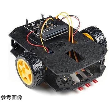 SparkFun micro:bot kit for micro:bit - v2.0SPARKFUN
¥22,980税込¥25,278
1個
33日以内出荷
DescriptionRobots are fun, and the micro:bit is the perfect controller for learning how to build and program robots! Combining the micro:bit with the SparkFun moto:bit carrier board creates a flexible, low-cost, Qwiic-enabled robotics platform for robot enthusiasts young and old! With the SparkFun micro:bot kit you will be able to create simple robots quickly without spending hours learning how to build and program your bot.Inside each micro:bot kit you will find all the components required to build your micro:bit into a robotics powerhouse; the only part that's not included is the micro:bit itself. Simply add your own micro:bit to the provided moto:bit, assemble the kit, and you will be ready to start moving. The SparkFun micro:bot kit is a great way to get your feet wet in the world of robotics.The kit does not require any soldering and is recommended for anyone curious about robotics or the micro:bit platform.Note:The SparkFun micro:bot kit doesNOTinclude a micro:bit board. The micro:bit board will need to be purchased separately.The micro:bit is a pocket-sized computer that lets you get creative with digital technology. Between the micro:bit and our shield-like bit boards you can do almost anything while coding, customizing and controlling your micro:bit from almost anywhere! You can use your micro:bit for all sorts of unique creations, from robots to musical instruments and more. At half the size of a credit card, this versatile board has vast potential!Get started with the micro:bot kit Guide
アズワン品番67-0424-41
 SparkFun FM Tuner Evaluation Board - Si4703SPARKFUN
¥6,698税込¥7,368
1個
33日以内出荷
DescriptionThis is an evaluation board for the Silicon Laboratories Si4703 FM tuner chip. Beyond enabling you to tune in to FM radio stations, the Si4703 is also capable of detecting and processing both Radio Data Service(RDS)and Radio Broadcast Data Service(RBDS)information. The Si4703 even does a very good job of filtering and carrier detection. It also enables data such as the station ID and song name to be displayed to the user.Using this board, you will be able to pick up multiple stations just as well as with a standard FM radio. The board breaks out all major pins and makes it easy to incorporate this great chip into your next radio project. The power bus, the 3.3V and GND pins are broken out For communication. The breakout provides access to SDIO and SCLK for I2C communication while RST can be used for easy resetting. The SEN pin enables the user to change the mode of functionality of the IC. The last two pins broken out are GPIO1 and GPIO2 which can be used as general input/output pins, but also can be used for things like the RDS ready, seeking or tuning functions.Keep in mind, by plugging headphones into the 3.5mm audio jack, you effectively use the cable in your headphones as an antenna! Therefore, this board does not require an external antenna if using headphones or a 3.5mm audio cable longer than 3 feet.
アズワン品番67-0429-34
 SparkFun Atmospheric Sensor Breakout - BME280SPARKFUN
¥6,898税込¥7,588
1個
33日以内出荷
DescriptionThe SparkFun BME280 Atmospheric Sensor Breakout is the easy way to measure barometric pressure, humidity, and temperature readings all without taking up too much space. Basically, anything you need to know about atmospheric conditions you can find out from this tiny breakout. The BME280 Breakout has been design to be used in indoor/outdoor navigation, weather forecasting, home automation, and even personal health and wellness monitoring.The on-board BME280 sensor measures atmospheric pressure from 30kPa to 110kPa as well as relative humidity and temperature. The breakout provides a 3.3V SPI interface, a 5V tolerant I2C interface(with pull-up resistors to 3.3V), takes measurements at less than 1mA and idles less than 5μA. The BME280 Breakout board has 10 pins, but no more than six are used at a single time. The left side of the board provide power, ground, and I2C pins. The remaining pins which provide SPI functionality and have another power and ground, are broken out on the other side.Note:The breakout does NOT have headers installed and will need to purchased and soldered on yourself. Check theRecommended Productssection below for the type of headers we use in the Hookup Guide!FeaturesOperation Voltage:3.3VI2C SPI Communications InterfaceTemp Range:-40C to 85CHumidity Range:0 - 100% RH, =-3% from 20-80%Pressure Range:30,000Pa to 110,000Pa, relative accuracy of 12Pa, absolute accuracy of 100PaAltitude Range:0 to 30,000 ft(9.2 km), relative accuracy of 3.3 ft(1 m)at sea level, 6.6(2 m)at 30,000 ft.Incredibly Small
アズワン品番67-0426-57
 Shapeoko 4 XL - Hybrid Table, with RouterSPARKFUN
¥739,800税込¥813,780
1個
33日以内出荷
DescriptionPlease note, these machines are built to order have an estimated lead time of 4 business days before shippingThis is the Shapeoko 4 XL, nearly double the cutting area of the Shapeoko 4 Standard! The Shapeoko is a 3-axis CNC Machine kit that allows you to create your 2D and 3D designs out of non-ferrous metals, hardwoods, and plastics. The Shapeoko 4 XL is designed to be affordable enough for any shop and powerful enough to do real work. Don't let the size intimidate you! This is an entry-level CNC machine designed for hobbyists, artists, and fabricators!Each Shapeoko 4 XL has a cutting area of 838.2mm(X)x 444.5 mm(Y)x 101.6mm(Z)(33"×17.5"×4")and an overall footprint of 1270mm(X)x 609.6mm(Y)x 482.6mm(Z)(50"×24"×19"). The power cable included in this kit is designed for the United States National Plug Standard. Don't forget you can put whatever you want on the adapter ring(as long as it fits), whether that's a laser, 3D print extrusion head, or a marker. Get creative!Upgrades from the Shapeoko 3 include:New, more rigid v-wheel design15mm beltsInductive homing switchesNew electronicsIntegrated t-slot Hybrid Table(OPTIONAL)Fully-supported Y extrusionsLeadscrew-driven Z-axisNew, more rigid 65mm router mountSweepy 65mm V2 dust bootNote:This item is non-returnable. If this item arrives damaged or is not functioning properly, please do not hesitate to contact us to see if further actions may be taken.Not Compatible with the Shapeoko 4:Expansion PacksT-Track Clamp KitsZ-PlusProximity Switch KitMaintenance KitShapeoko 3 Bit SetterHDZ 4.0FeaturesFootprint:1270mm×609.6mm×482.6mm(50"×24"×19")Cutting Area:838.2mm×444.5mm×101.6mm(33"×17.5"×4")Weight 137lbs.Operating System:Mac(OSX 10.14 or higher)or PC(Windows 8.1 or 10, Intel or AMD)
アズワン品番67-0428-90
 LIDAR-Lite v3HPSPARKFUN
¥37,980税込¥41,778
1個
33日以内出荷
DescriptionLIDAR has never looked so good! This is the LIDAR-Lite v3HP, a compact, high-performance optical distance measurement sensor from Garmin(TM). The LIDAR-Lite v3HP istheideal optical ranging solution for drone, robot, or unmanned vehicle applications. Each sensor is housed in a durable, IPX7-rated housing and includes all the core features and user configurability of the popular LIDAR-Lite v3.The v3HP is very similar in function to that of the v3 but it can now sample faster at rates greater than 1kHz(where as the v3 is only capable of up to 500Hz). Another improvement is that this v3HP model is more power efficient with current consumption rates 40mA less than the v3(that's 65mA as opposed to 105mA while idle, and 85mA instead of 130mA while acquiring).Each LIDAR-Lite v3HP has a range of 1m to 40m and features an edge-emitting, 905nm(1.3 watts), single-stripe laser transmitter, 8m Radian beam divergence, and an optical aperture of 12.5mm. This version of the LIDAR-Lite still operates at 5VDC(6V max)with a peak power of 1.3W and still possesses an accuracy of +/- 2.5cm at >2m. On top of everything else, the LIDAR-Lite is user-configurable, allowing adjustment between accuracy, operating range and measurement time and can be interfaced via I2C or PWM with the attached 200mm cable.Note:CLASS 1 LASER PRODUCT CLASSIFIED EN/IEC 60825-1 2014. This product is in conformity with performance standards for laser products under 21 CFR 1040, except with respect to those characteristics authorized by Variance Number FDA-2016-V-2943 effective September 27, 2016.Get Started with the LIDAR-Lite v3HP GuideFeaturesResolution:1 cmTypical accuracy:+/- 2.5cm at distances greater than 2 meters(Refer to operating manual for complete operating specifications)Range:1m to 40mUpdate rate:Greater than 1kHzInterface:I2C or PWMPower(operating voltage):4.75-5VDC; 6V MaxCurrent consumption:65ma idle; 85ma during acquisitionOperating temperature:-20℃ to 60℃Laser wave length/Peak power:905nm/1.3WBeam divergence:8m RadianOptical aperture:12.5mmWater rating:IPX7Unit dimensions:24.5mm×53.5mm×33.5mm(1.0in×2.1in×1.3in)Weight:34g(1.2oz)
アズワン品番67-0426-76
 Reversible USB A to C Cable - CABシリーズSPARKFUN
¥1,698税込¥1,868
1個
33日以内出荷
DescriptionUSB-C is fantastic. What makes this cable even better is that one of the features we love so much about USB-C has been replicated to the USB-A 2.0 plug! These cables have minor, yet genius modifications that allow them to be plugged into their ports regardless of orientation. No longer will you fight the USB "super position" where both orientations of your plug seem incorrect. A simple solution to a problem that nearly everyone has faced.Until we have converted all our hubs, chargers, and ports over to USB-C this is the cable you're going to need for basic USB 2.0 connections. This cable is much thinner and flexible than its 3.1 counterpart and is perfect for USB to serial applications as well as for direct connection to basic microcontrollers.This cable has the D+/D- wires along side large-gauge VBUS/GND wires. Rated for 2A, we've successfully pulled 2A@5V with minimal voltage drop. If you're looking for a the full USB-C implementation checkout our USB 3.1 cable.FeaturesReversible USB-A connectorReversible USB-C connector
アズワン品番67-0420-52
 Transistor - NPN, 60V 4A 2N5192GSPARKFUN
¥349税込¥384
1個
33日以内出荷
DescriptionThis is the 2N5192G, an NPN silicon transistor. This little transistor can help in your project by being used to help drive large loads or amplifying or switching applications. The 2N5192G is specifically rated at 60V and 4A max.
アズワン品番67-0420-88
 SparkFun MicroMod Qwiic Carrier Board - SingleSPARKFUN
¥2,898税込¥3,188
1個
33日以内出荷
DescriptionThe MicroMod Qwiic Carrier Board can be used to rapidly prototype with other Qwiic devices. The MicroMod M.2 socket provides users the freedom to experiment with any processor board in the MicroMod ecosystem. This board also features two Qwiic connectors and four 4-40 screw inserts to connect and mount Qwiic devices.This version of the SparkFun MicroMod Qwiic Carrier Board features a single port for our standard 1in. by 1in. Qwiic Breakouts. However, you aren't beholden to attaching just one Qwiic breakout since you are able to stack the boards on top of each other, allowing you to hook up a full circuit of Qwiic sensors and accessories to fully utilize your next project!MicroMod is a modular interface ecosystem that connects a microcontroller "processor board" to various "carrier board" peripherals. Utilizing the M.2 standard, the MicroMod standard is designed to easily swap out processors on the fly. Pair a specialized carrier board for the project you need with your choice of compatible processor!Get Started With the MicroMod Qwiic Carrier Board GuideFeaturesM.2 MicroMod(Processor Board)ConnectorUSB-C Connector3.3V 1A Voltage RegulatorQwiic ConnectorsBoot/Reset ButtonsCharge CircuitFour 4-40 Inserts
アズワン品番67-0423-50
 SparkFun LTE GNSS Breakout - SARA-R5SPARKFUN
¥36,980税込¥40,678
1個
33日以内出荷
DescriptionNote - Please read before purchasing!:The SparkFun LTE GNSS Breakout - SARA-R5 uses the "00B" product version of the SARA-R5 module(specifically the SARA-R510M8S-00B-00). LTE NB-IoT Radio Access Technology, and the LTE FDD bands:66, 71, 85 are not supported by this version. Refer to the SARA-R5 datasheet for more information.The SparkFun SARA-R5 LTE GNSS Breakout is a robust development tool for u-blox's impressive SARA-R510M8S module. The SARA-R510M8S combines u-blox's UBX-R5 cellular chipset with their M8 GNSS receiver chipset to provide a 5G-Ready wireless IoT device complete with positioning data all on a single chip. As an asset tracker, the LTE GNSS Breakout offers Secure Cloud LTE-M communication for multi-regional use and has an integrated u-blox M8 GNSS receiver for accurate positioning information.The UBX-R5 chipset supports many different forms of data communication from full TCP/IP sockets and packet switched data, through HTTP Get/Put/Post, FTP(the SARA has a built-in file system), Ping, to good old SMS text messaging! The built-in u-blox M8 GNSS receiver provides accurate and reliable positioning with a separate GNSS antenna interface for an external antenna. Both the GNSS antenna and LTE connections are made via a pair of SMA connectors.This breakout routes nearly all of the functional pins on the SARA-R510M8S module to user interfaces(USB or plated-through hole)so you can take full advantage of all of the features available on this impressive LTE/GNSS module. The SARA-R5's UART interface can be configured into one of five variants, providing connectivity over one or two UARTs. A separate USB port provides access to the SARA's trace log for diagnostic purposes. This breakout provides access to all three interfaces(UART1, UART2 and SARA Diag)via three separate USB-C connections. All eight 3.3V serial signals are available on a 0.1"-pitch breakout header. Separate 0.1"-pitch headers break out the SARA's I2C bus, power pins as well as GPIO pins for various functionalities.Get Started with the SARA-R5 LTE GNSS Breakout GuideFeaturesu-blox SARA-R510M8S module providing Secure Cloud LTE-M data communication for multi-regional usePlease check that your service provider offers LTE-M coverage for your area before purchasingIntegrated u-blox M8 GNSS receiver for accurate positioning informationNano SIM socketSeparate, robust SMA connections for LTE and GNSS antennasSwitchable 3.3V power for an active GNSS antennaUSB-C connectivityLED indicators for:Power(VIN and 3.3V)SARA-R5 onNetwork indicatorGNSS timing pulse(1PPS)3.3V plated through-hole(PTH)pins for:SARA onNetwork indicatorUART1GNSS timing pulse(1PPS)I2C bus
アズワン品番67-0423-92
 SparkFun Inventor's Kit for micro:bit v2 Lab PackSPARKFUN
¥149,800税込¥164,780
1個
33日以内出荷
DescriptionThe SparkFun Inventor's Kit for micro:bit v2 Lab Pack includes 10 complete micro:bit v2 Inventor's Kits, an SIK Refill Pack and 25 AAA-sized batteries to get your students started in the world of electronics. The SIKs inside the Lab Pack have everything you need, including micro:bit v2s, connector breakouts, breadboards and all the cables and accessories to hook up all the projects listed in our online Experiment Guide.The kit does not require any soldering and is recommended for all users, from beginners to engineering students. We have provided a complete Experiment Guide in the Documents tab for you to check out now! If you are new to teaching electronics or have taught with the original SparkFun Inventor's Kit and are looking for something new, the SIK for micro:bit v2 is the perfect kit for you!SparkFun packages everything educators need to get started with this platform in a variety of classroom and makerspace settings with diverse student populations. The hardware boards, cables and extra parts come pre-packaged, and our online support materials --- including an online Experiment Guide(to be updated)--- help you bring the power of the open source community to your classroom. Examples and curriculum materials are available from SparkFun and Arduino, as well as from other educators involved in this growing maker movement.The micro:bit is a pocket-sized computer that lets you get creative with digital technology. Between the micro:bit and our shield-like bit boards you can do almost anything while coding, customizing and controlling your micro:bit from almost anywhere! You can use your micro:bit for all sorts of unique creations, from robots to musical instruments and more. At half the size of a credit card, this versatile board has vast potential!
アズワン品番67-0424-93
 SparkFun Inventor's Kit for micro:bit v2SPARKFUN
¥15,980税込¥17,578
1個
33日以内出荷
DescriptionThe SparkFun Inventor's Kit(SIK)for micro:bit v2 is a great way to get creative, connected and coding with the micro:bit. The SIK for micro:bit v2 provides not only the micro:bit v2 board but everything you need to hook up and experiment with multiple electronic circuits! With the SIK for micro:bit v2 you will be able to complete circuits that will teach you how to read sensors, move motors, build Bluetooth(R)devices and more.The SparkFun Inventor's Kit for micro:bit is the latest and greatest in single-board computer kits. Surrounding the micro:bit v2 SIK is one core philosophy --- that anyone can(and should)experiment with cutting-edge electronics in a fun and playful way without breaking the bank.The kit does not require any soldering and is recommended for all users, from beginners to engineers. We have provided a complete Experiment Guide in the Documents tab for you to check out now! If you have ever been interested in learning about electronics, or if you have used the original SparkFun Inventor's Kit and are looking for something new, the SIK for micro:bit is the perfect kit for you!The micro:bit is a pocket-sized computer that lets you get creative with digital technology. Between the micro:bit and our shield-like bit boards you can do almost anything while coding, customizing and controlling your micro:bit from almost anywhere! You can use your micro:bit for all sorts of unique creations, from robots to musical instruments and more. At half the size of a credit card, this versatile board has vast potential!ExamplesCircuit 0:Hello, micro:bit!Circuit 1:Blinking an LEDCircuit 2:Reading a PotentiometerCircuit 3:Reading a PhotoresistorCircuit 4:Driving an RGB LEDCircuit 5:Reading an SPDT SwitchCircuit 6:Reading a Button PressCircuit 7:Reading the Temperature SensorCircuit 8:Using a Servo MotorCircuit 9:Using a BuzzerCircuit 10:Using the AccelerometerCircuit 11:Using the Compass
アズワン品番67-0424-61
 SparkFun I2S Audio Breakout - MAX98357ASPARKFUN
¥1,698税込¥1,868
1個
33日以内出荷
DescriptionThe SparkFun I2S Audio Breakout board uses the MAX98357A digital to analog converter(DAC), which converts I2S(not be confused with I2C)audio to an analog signal to drive speakers. The I2S Audio Breakout converts the digital audio signals using the I2S standard to an analog signal and amplifies the signal using a class D amplifier which can deliver up to 3.2W of power into a 4Ω load. The board can be configured to output only the left channel audio, right channel, or both.The SparkFun I2S Audio Breakout board is fairly simple, requiring only a few pin connections to get it up and working. By default the board is configured in "mono" operation, meaning the left and right signals are combined together to drive a single speaker. If you want a separate speaker for the left and right audio channels you'll need to cut the mono jumper. In addition to being able to select the audio channel output, the gain can also be configured in a few ways. The gain of the amplifier can be configured from as low as +3dB to as high as +15dB. While the channel selection can be configured on board, the gain however is controlled externally using the gain pin. By default, the board is configured for +9dB, but can be easily changed!Get Started with the SparkFun I2S Audio Breakout GuideFeaturesSupply Voltage Range:2.5V - 5.5V.Output Power:3.2W into 4Ω at 5V.Output Channel Selection:Left, Right, or Left/2 + Right/2(Default).Sample Rate:8kHz - 96kHz.Sample Resolution:16/32 bit.Quiescent Current:2.4mA.Filterless Class D OutputsNo MCLK RequiredClick and Pop ReductionShort-Circuit and Thermal Protection.
アズワン品番67-0422-64
 SparkFun Breadboard Power Supply 5V/3.3VSPARKFUN
¥3,598税込¥3,958
1個
33日以内出荷
Here is a very simple breadboard power supply kit that takes power from a DC wall wart and outputs a selectable 5V or 3.3V regulated voltage. The .1" headers are mounted on the bottom of the PCB for simple insertion into a breadboard. Pins labeled VCC and GND plug directly into the power lines. The lone pair of pins have no electrical connection but help support the PCB.There are two pins available within the barrel jack footprint. Any stripped +/- DC supply can be connected instead of the barrel connector. Board has both an On/Off switch and a voltage select switch(3.3V/5V).Comes as a bag of parts kit and is easily assembled if you can follow the silkscreen indicators and have beginning experience with a soldering iron. You will need to read the resistor bands or use a multimeter to determine the resistor sizes.Dimensions:1.25x1.25"Kit Includes:DC Barrel Connector(2.1mm center positive)TO-220 Voltage Regulator(LM317 1.5A max current)1N4004 Reverse Protection Diode100uF 25V Capacitor10uF 25V Capacitor0.1uF 50V CapacitorRed Power LED - High Brightness2×SPDT Slide Switch4×0.1" Header Pins2×330 Resistor 1/6W390 Resistor 1/6W240 Resistor 1/6WBare PCB with Silkscreen IndicatorsPTC resettable fuse
仕様●項目1:組込み(組立てキット)●項目2:電源●項目4:リニア電源●項目8:ブレッドボード用電源アズワン品番67-0454-01
 Raspberry Pi PoE+ HATSPARKFUN
¥7,498税込¥8,248
1個
33日以内出荷
DescriptionThe Raspberry Pi PoE+ HAT is designed to replace the existing Raspberry Pi PoE HAT in all new and existing designs. Like the original, the PoE+ HAT allows you to power your Raspberry Pi using Power over Ethernet networks. The PoE+ HAT meets all the requirements of the IEEE 802.3af(802.3at Type 1, PoE+)specifications. This ups the power the network can supply from 15.4 watts(PoE)to 25.5 Watts(PoE+)over CAT5 cable.No modification to the main Raspberry Pi board is needed for the PoE+ HAT to work but you will need to ensure that your Pi's software is up to date for all functionality to be available. The Raspberry Pi PoE+ HAT is fitted with a small fan that is controlled by the Raspberry Pi via I2C and will turn on and off automatically depending on the temperature of the main processor on your Pi.Note:There is no Raspberry Pi included with this product. Your desired Pi will need to be purchased separately.FeaturesInput voltage:37-57V DC, Class 2 deviceOutput power:5V DC/3.0ACooling:25mm×25mm brushless fan delivering 2.2CFM forprocessor coolingFully isolated switch-mode power supplyFan controlMechanically compatible with the existing Raspberry Pi PoE HAT
アズワン品番67-0423-62
 Raspberry Pi Camera Module - Pi NoIR V2SPARKFUN
¥10,980税込¥12,078
1個
33日以内出荷
DescriptionThis 8MP IR(Infrared)camera module is capable of 1080p video and still images and connects directly to your Raspberry Pi. Similar to the non-IR version Raspberry Pi Camera, connect the included ribbon cable to the CSI(Camera Serial Interfac
アズワン品番67-0423-31
 SparkFun OpenLogSPARKFUN
¥4,698税込¥5,168
1個
予約販売
microSDカードを使用したデータロガー32GBまでのmicroSDカードを使用して、シリアル接続により動作するデータロガーです。大量のデータを保存することができます。16MHzで動作するATmega328を搭載し、記録していないアイドルモードでの消費電力は約2~3mAです。
仕様●電源電圧:3.3V~12V(3.3V~5Vを推奨)●microSDカード:最大32GB、FAT16/32に対応●シンプルなコマンドインターフェース●ボーレートを設定可能(115200bpsまで)●ATmega328にブートローダを設定済み●SPI×4●LED×2(書き込み状態を示す)●消費電力:アイドル時 2mA、記録時 6mA●※Arduino IDE 1.6.7 ではコンパイルできません。1.6.5でのコンパイルが必要です。1.6.5以外は未検証となります。アズワン品番67-0398-95
 Kitronik MI:power Board V2SPARKFUN
¥2,598税込¥2,858
1個
33日以内出荷
DescriptionThe MI:power board for the BBC micro:bit brings real portability to your wearable projects. The stylish, lightweight PCB is designed to fit snugly against the BBC micro:bit and features a built-in buzzer and 3V coin cell holder. This la
アズワン品番67-0423-58
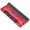
 SparkFun Qwiic pHAT Extension for Raspberry Pi 400SPARKFUN
¥1,798税込¥1,978
1個
33日以内出荷
DescriptionThe SparkFun Qwiic pHAT Extension for the Raspberry Pi 400 provides you with a quick and easy solution to access all of the 400's GPIO, stack your favorite HAT right-side up, or connect a Qwiic-enabled device to the I2C bus(GND, 3.3V, SDA
アズワン品番67-0423-40
 V-Bit Cutter - 0.5" Diameter, 90 Degree, #301 2 PackSPARKFUN
¥22,980税込¥25,278
1個
33日以内出荷
DescriptionThis is a two pack of V-Bit mills from Carbide 3D that are perfect for engraving intricate patterns and fine details. Each mill in this pack features a cutting diameter of 0.5 inches, a shank diameter of 0.25 inches, and a cutting angle of 90℃. These cutters really are great for precision 3D machining and fabrication.Each cutter is made of solid carbide to ensure long lasting use.Note:If you are using these cutters with a Nomad, you will also need a 0.25in collet.FeaturesCutting Diameter:0.5"Cutting Length:0.25"Shank Diameter:0.25"90℃ Cutting Angle2 Flute
アズワン品番67-0428-51
 SparkFun Real Time Clock Module - RV-8803 QwiicSPARKFUN
¥4,998税込¥5,498
1個
33日以内出荷
DescriptionThe SparkFun RV-8803 Real Time Clock Module is a Qwiic-enabled breakout board for the RV-8803 RTC. The RV-8803 boasts some impressive features including a temperature compensated crystal providing extremely precise time-keeping, low power consumption, and time stamp event input along with a user-programmable timing offset value. The RV-8803 also has an improved I2C interface compared to the RV-1805 RTC that removes the need to sequence commands/writes to the device. Best of all, the temperature compensation comes factory calibrated. Utilizing our handy Qwiic system so no soldering is required to connect it to the rest of your system. However, we still have broken out 0.1"-spaced pins in case you prefer to use a breadboard.Adding a real-time clock to your project is the perfect way to get more accurate data; timing or otherwise. Using the Qwiic connector makes for a fast, solid way to incorporate this into your project. The RTC module has counters for hundredths of seconds, seconds, minutes, hours, date, month, year and weekday with a number of alarm and interrupt settings available as well. Plus the large operating temperature range(-40 to +105℃)and temperature compensated crystal makes for a good addition for field applications or harsh environments.The SparkFun Qwiic Connect System is an ecosystem of I2C sensors, actuators, shields and cables that make prototyping faster and less prone to error. All Qwiic-enabled boards use a common 1mm pitch, 4-pin JST connector. This reduces the amount of required PCB space, and polarized connections mean you can't hook it up wrong.Get Started with the SparkFun RV-8803 Real Time Clock Module GuideFeaturesFactory Calibrated Temperature CompensationHigh Time Accuracy±1.5 ppm 0 to +50℃±3.0 ppm -40 to +85℃±7.0 ppm +85 to +105℃1.5V to 5.5V Operating Voltage Range240nA @ 3.3v Low-Power ConsumptionI2C Address:0x32Periodic Countdown Timer Interrupt functionPeriodic Time Update Interrupt function(seconds, minutes)Alarm Interrupts for weekday or date, hour and minute settingsExternal Event Input with Interrupt and Time Stamp functionProgrammable Clock Output pin for peripheral devices.Operating temperature range:-40 to +105℃2x Qwiic Connectors
アズワン品番67-0420-10
 SparkFun Qwiic pHAT v2.0 for Raspberry PiSPARKFUN
¥1,998税込¥2,198
1個
33日以内出荷
DescriptionThe SparkFun Qwiic pHAT V2.0 for Raspberry Pi provides you with the quickest and easiest way to enter into SparkFun's Qwiic ecosystem while still using that Raspberry Pi that you've come to know and love. The Qwiic pHAT connects the I2C bus(GND, 3.3V, SDA, and SCL)on your Raspberry Pi to an array of Qwiic connectors on the HAT. Since the Qwiic system allows for daisy-chaining boards with different addresses, you can stack as many sensors as you'd like to create a tower of sensing power!The Qwiic pHAT V2.0 has four Qwiic connect ports(two on its side and two vertical), all on the same I2C bus. We've also made sure to add a simple 5V screw terminal to power boards that may need more than 3.3V and a general-purpose button(with the option to shut down the Pi with a script). Also updated, the mounting holes found on the board are now spaced to accommodate the typical Qwiic board dimension of 1.0"×1.0". This HAT is compatible with any Raspberry Pi that utilizes the standard 2x20 GPIO header as well as the NVIDIA Jetson Nano and Google Coral.NoteWhen placing a Raspberry Pi and the pHAT in an enclosure(like the Pi Tin), we noticed that the pHAT was not fully inserted in Pi's header pins. For a secure connection, you'll need to add a pair of 1x20 stackable headers to extend the pins to your cart.The SparkFun Qwiic Connect System is an ecosystem of I2C sensors, actuators, shields and cables that make prototyping faster and less prone to error. All Qwiic-enabled boards use a common 1mm pitch, 4-pin JST connector. This reduces the amount of required PCB space, and polarized connections mean you can't hook it up wrong.Get Started with the SparkFun Qwiic pHAT GuideFeatures4x Qwiic Connection Ports1x 5V Tolerant Screw Terminal1x General Purpose ButtonHAT-compatible 40-pin Female Header
アズワン品番67-0422-97
 SparkFun Cryptographic Co-Processor Breakout - ATECC608A QwiicSPARKFUN
¥1,198税込¥1,318
1個
33日以内出荷
DescriptionProduct Restrictions:To access certain features of the ATECC608A, users will need to contact Microchip and sign an NDA contract to obtain the complete datasheet. Due to the required NDA - technical support, an Arduino library, and hookup guide are not provided for users on this product.The SparkFun ATECC608A Cryptographic Co-processor Breakout allows you to add strong security to your IoT node, edge device, or embedded system. This includesasymmetricauthentication,symmetricAES-128 encryption/decryption, and much more. As stated above, the ATECC608A has limited Arduino support and the complete datasheet is under NDA with Microchip.This breakout board includes two Qwiic ports for plug and play functionality. Utilizing our handy Qwiic system, no soldering is required to connect it to the rest of your system. However, we still have broken out 0.1"-spaced pins in case you prefer to use a breadboard. The ATECC608A chip is capable of many cryptographic processes, including, but not limited to:Creating and securely storing unique asymmetric key pairs based on Elliptic Curve Cryptography(FIPS186-3).AES-128:Encrypt/Decrypt, Galois Field Multiply for GCMCreating and verifying 64-byte digital signatures(from 32-bytes of message data).Creating a shared secret key on a public channel via Elliptic Curve Diffie-Hellman Algorithm.SHA-256 HMAC Hash including off-chip context save/restoreInternal high quality FIPS random number generator.Embedded in the chip is a 10Kb EEPROM array that can be used for storing keys, certificates, data, consumption logging, and security configurations. Access to the sections of memory can then be restricted and the configuration locked to prevent changes. Each ATECC608A Breakout ships with a guaranteed unique 72-bit serial number and includes several security features to prevent physical attacks on the device itself, or logical attacks on the data transmitted between the device.A summary datasheet for the ATECC608A is available here. The full datasheet is under NDA with Microchip. You will need to contact them for access to the entire datasheet. Meanwhile, the ArduinoATECCX08 Library currently only supports the ATECC608A with SAMD21 Arduino boards.We do have much more support for the ATECC508A version of this chip. Please check out our ATECC508A Hookup Guide and Arduino Library(which includes six examples). This will get you familiar with the basics of elliptic curve cryptography and signing/verifying data with the ATECC508A version of the chip.Note:The I2C address of the ATECC608A is 0x60 and is software-configurable to any address. A multiplexer/Mux is required to communicate to multiple ATECC608A sensors at the default address when on a single bus. If you need to use more than one ATECC608A sensor at the default address, consider using the Qwiic Mux Breakout.Note:The ATECC608A can be only configured once before it isPERMANENTLYlocked. It is advisable that users purchase multiple boards in order to use other configurations and explore the advanced functions of the ATECC608A.Additionally, this boardIScapable of encrypting and decrypting data. However, to access these additional features, you will need to contact Microchip and sign an NDA contract to obtain the complete datasheet.It is recommended that an SparkFun RedBoard Turbo - SAMD21 Development Board is used with this product due to the buffer size required on the I2C bus.The SparkFun Qwiic Connect System is an ecosystem of I2C sensors, actuators, shields and cables that make prototyping faster and less prone to error. All Qwiic-enabled boards use a common 1mm pitch, 4-pin JST connector. This reduces the amount of required PCB space, and polarized connections mean you can't hook it up wrong.FeaturesOperating Voltage:2.0V-5.5V(Default on Qwiic System:3.3V)Active Current Draw(for ATECC608A):16 mASleep Current(for ATECC608A):<150 nAGuaranteed Unique 72-bit Serial Number10 Kb EEPROM Memory for Keys, Certificates, and DataStorage for up to 16 Keys256-bit Key LengthInternal High-Quality FIPS Random Number Generator(RNG)Configurable I2C Address(7-bit):0x60(Default)
アズワン品番67-0423-59
 SparkFun Capacitive Touch Slider - CAP1203 QwiicSPARKFUN
¥2,198税込¥2,418
1個
33日以内出荷
DescriptionDo you want to replace a slider or a button on your art project or science experiment with a more interesting interface? This Capacitive Touch Slider is a "Qwiic" and easy way to add capacitive touch to your next project. With the board's built in touch pads, you can immediately start playing with the touch capabilities as three unique touch inputs or as a slider. You can also enable a touch input to act as a power button, customize the sensitivity for your own touch pads, and play with the interrupt alert LED. Utilizing our Qwiic system, no soldering is required to connect it to the rest of your system. However, we have broken out 0.1"-spaced pins in case you prefer to use a breadboard or create your own touch pads.On the front of the board, there is an arrow shape which contains three separate capacitive touch pads. We also broke out the capacitive touch sensor lines as plated through-holes on the top of the board. You can use these pins to connect to your own capacitive touch pads. The CS1 pin connects to the left pad, the CS2 pin connects to the middle pad, and the CS3 pin connects to the right pad.NOTE:The I2C address of the CAP1203 is 0x28 and is hardware defined. A multiplexer/Mux is required to communicate to multiple CAP1203 sensors on a single bus. If you need to use more than one CAP1203 sensor consider using the Qwiic Mux Breakout.The SparkFun Qwiic connect system is an ecosystem of I2C sensors, actuators, shields and cables that make prototyping faster and less prone to error. All Qwiic-enabled boards use a common 1mm pitch, 4-pin JST connector. This reduces the amount of required PCB space, and polarized connections mean you can't hook it up wrong.Get Started with the SparkFun Capacitive Touch Slider GuideFeaturesCapacitive Touch3 unique capacitive touch inputsFeaturesEmulated sliderPower button settingProgrammable sensitivityAutomatic recalibrationI2C Address:0x28Qwiic EnabledOperating RangeSupply Voltage:3.3V - 5V
アズワン品番67-0427-06
 SparkFun BabyBuck Regulator Breakout - 3.3V AP63203SPARKFUN
¥1,298税込¥1,428
1個
33日以内出荷
DescriptionWho doesn't occasionally need power regulation? We certainly do, so we've designed the SparkFun BabyBuck Regulator Breakout to help us with just such a task. Featuring the AP63203 from Diodes Inc, this breakout board takes advantage of a 2A synchronous buck converter that has a wide input voltage range of 3.8V to 32V and fully integrated 125mΩ high-side power MOSFET/68mΩ lowside power MOSFET to provide high-efficiency step-down DC/DC conversion. All of this snuggled up in a low-profile, TSOT26 package that's integrated into a 0.4in by 0.5in board.Unlike it's sibling, the BabyBuck sacrifices power option flexibility for space. Don't worry, though, because you can still use the plated through holes for input and output power. With some simple right-angle headers, you'll be up and running in no time.Frequency Spread Spectrum(FSS)reduces EMI and a proprietary gate driver scheme resists switching node ringing without sacrificing MOSFET turn-on and turn-off times, which further erases high-frequency radiated EMI noise.Get Started with the SparkFun Buck Regulator Hookup GuideFeaturesLow-Profile FootprintVIN 3.8V to 32VVOUT 3.3VUp to 2A Continuous Output Current0.8V ± 1% Reference Voltage22μA Ultralow Quiescent CurrentSwitching Frequency - 1.1MHzSupports Pulse Frequency Modulation(PFM)Up to 80% Efficiency at 1mA Light LoadUp to 88% Efficiency at 5mA Light LoadFixed Output Voltage - 3.3VProprietary Gate Driver Design for Best EMI ReductionFrequency Spread Spectrum(FSS)to Reduce EMIPrecision Enable Threshold to Adjust UVLOProtection CircuitryOvervoltage ProtectionCycle-by-Cycle Peak Current LimitThermal Shutdown
アズワン品番67-0421-86
 Leopard Imaging Camera - 136 Degree FOVSPARKFUN
¥10,980税込¥12,078
1個
33日以内出荷
DescriptionThe Leopard Imaging Camera is a 136° FOV(field of view)wide angle camera module that is great for machine vision applications, and designed specifically to be compatible with the NVIDIA Jetson Nano Developer Kit. This camera incorporates a Sony IMX219 8.08MP color sensor, a fixed focus(M8)lens, and utilizes CSI-2 MIPI 2-lane data output interface.This is the same camera that we include in the SparkFun Jetbot v2.1 Kit.Note:SparkFun has not established the compatibility of this camera with Raspberry Pi. We are currently working with the manufacturer, but due to firmware restrictions Leopard cameras do not work with any Raspberry Pi's at this time.FeaturesField of view(FOV):136°Module size:150mm(L)x 25mm(W)Sensor type:Sony IMX219 8.08MP color sensorActive pixels:3280(H)x 2464(V)Image size:Diagonal 4.60mm(Type 1/4.0)F/No:2.0(H136)Focal length:1.58mm(H136)TV distortion:<-15%(H136)Focusing range:30cm - InfinityLens type:Fixed Focus(M8 lens)Pixel size:1.12um×1.12umData output interface:CSI-2 MIPI 2-laneIR Cutter Filter:Yes
アズワン品番67-0422-99
 I/O Expander - MCP23008SPARKFUN
¥599税込¥659
1個
33日以内出荷
DescriptionAdd another eight pins to your microcontroller using a MCP23008 port expander. The MCP23008 uses two I2C pins which can be shared with other I2C devices, and in exchange gives you eight general purpose pins. You can set each of eight pins to be input, output, or input with a pullup. There's even the ability to get an interrupt via an external pin when any of the inputs change so you don't have to keep polling the chip.Use this chip from 2.7-5.5V(good for any 3.3V or 5V setup), and you can sink/source up to 20mA from any of the I/O pins so this will work for LEDs and such. Team it up with a high-power MOSFET if you need more juice. DIP package means it will plug into any breadboard or perfboard.You can set the I2C address by tying the ADDR0-2 pins to power or ground, for up to eight unique addresses. That means eight chips can share a single I2C bus - that's 64 I/O pins!Features8-bit remote bidirectional I/O portHigh-speed I2C interface(MCP23008)Hardware address pinsConfigurable interrupt output pinConfigurable interrupt sourcePolarity Inversion register for input port data polarity config.External reset inputLow standby current:1 μA(max.)・ Operating voltage:1.8V to 5.5V @ -40℃ to +85℃ I2C @ 100 kHz SPI @ 5 MHz2.7V to 5.5V @ -40℃ to +85℃ I2C @ 400 kHz SPI @ 10 MHz4.5V to 5.5V @ -40℃ to +125℃ I2C @ 1.7 kHz SPI @ 10 MHz
アズワン品番67-0421-32
 Himax CMOS Imaging Camera - HM01B0SPARKFUN
¥3,298税込¥3,628
1個
33日以内出荷
DescriptionThe HM01B0 from Himax Imaging is an ultra low power CMOS Monochrome Image Sensor that enables the integration of an "Always On" camera for computer vision applications such as gestures, intelligent ambient light and proximity sensing, tracking and object identification. The sensor allows the sensor to consume very low power of <2mW at QVGA 30FPS. This low power consumption and vision applications camera comes with a ribbon cable that mates to the camera connector populated on the following products:MicroMod Machine Learning Carrier BoardArtemis Development KitEdge Development Board - Apollo3 BlueThe HM01B0 contains 320×320 pixel resolution and supports a 320×240 window mode which can be readout at a maximum frame rate of 60FPS, and a 2×2 monochrome binning mode with a maximum frame rate of 120FPS. The video data is transferred over a configurable 1bit, 4bit or 8bit interface with support for frame and line synchronization. The sensor integrates black level calibration circuit, automatic exposure and gain control loop, self-oscillator and motion detection circuit with interrupt output to reduce host computation and commands to the sensor to optimize the system power consumption.FeaturesImage SensorUltra Low Power Image Sensor(ULPIS)designed for Always On vision devices and applicationsHigh sensitivity 3.6μ BrightSenseTM pixel technology320×320 active pixel resolution with support for QVGA window, vertical flip and horizontal mirror readoutProgrammable black level calibration target, frame size, frame rate, exposure, analog gain(up to 8x)and digital gain(up to 4x)Automatic exposure and gain control loop with support for 50 / 60Hz flicker avoidanceFlexible 1bit, 4bit and 8bit video data interface with video frame and line syncMotion Detection circuit with programmable ROI and detection threshold with digital output to serve as an interruptOn-chip self oscillatorI2C 2-wire serial interface for register accessHigh CRA for low profile module designSensor ParametersActive Pixel Array 320×320Pixel Size 3.6 μm×3.6 μmFull Image Area 1152 μm×1152 μmDiagonal(Optical Format)1.63 mm(1/11″)Scan Mode:ProgressiveShutter Type:Electronic Rolling ShutterFrame Rate MAX 51 fps @ 320×320, 60 fps @ 320×240(QVGA)CRA(maximum)30℃Sensor SpecificationsSupply Voltage:Analog - 2.8 V, Digital - 1.5V(Internal LDO:1.5V - 2.8V), I/O - 1.5 - 2.8VInput Reference Clock:3 - 50 MHzSerial Interface(I2C):2-wire, 400 KHz max.Video Data Interface:1b, 4b, 8b with frame / line SYNCOutput Clock Rate MAX:50 MHz for 1bit, 12.5 MHz for 4bit, 6.25 MHz for 8bitEst. Power Consumption(include IO with 5pF load):QVGA 60FPS(Typical)<4 mWQVGA 30FPS(Typical)<2 mW
アズワン品番67-0427-08
 Reversible USB A to C Cable - CABシリーズSPARKFUN
¥1,998税込¥2,198
1個
33日以内出荷
DescriptionUSB-C is fantastic. What makes this cable even better is that one of the features we love so much about USB-C has been replicated to the USB-A 2.0 plug! These cables have minor, yet genius modifications that allow them to be plugged into their ports regardless of orientation. No longer will you fight the USB "super position" where both orientations of your plug seem incorrect. A simple solution to a problem that nearly everyone has faced.Until we have converted all our hubs, chargers, and ports over to USB-C this is the cable you're going to need for basic USB 2.0 connections. This cable is much thinner and flexible than its 3.1 counterpart and is perfect for USB to serial applications as well as for direct connection to basic microcontrollers.This cable has the D+/D- wires along side large-gauge VBUS/GND wires. Rated for 2A, we've successfully pulled 2A@5V with minimal voltage drop. If you're looking for a the full USB-C implementation checkout our USB 3.1 cable.FeaturesReversible USB-A connectorReversible USB-C connector
アズワン品番67-0420-51
 MI:pro Mountable Case for micro:bit V2SPARKFUN
¥1,798税込¥1,978
1個
33日以内出荷
DescriptionThe Mountable MI:pro is a simple and compact protective case for the micro:bit. This case has been specifically designed with portability and expansion in mind and is compatible with both the original micro:bit V1 and the micro:bit V2. These cases feature a three-layer construction style with ability to wall-mount the whole assembly onto any surface you want while still providing access to all buttons and ports on the micro:bit. Though these cases do feature wall-mountable tabs, the biggest benefit of using a case is to not accidentally short out the pads on the back of the micro:bit.Construction is simple, requiring only a small flathead screwdriver, and involves layering each plate on top of one another around the micro:bit and screwing it into place. Luckily, the MI:pro case enables easy access to the edge pins at the bottom of the micro:bit, allowing it to still be plugged into an edge connector found on many of our carrier boards. The only board that cannot be used in conjunction with the MI:pro case is the SparkFun gamer:bit due to its edge connector being located in the center of the board.Note:The MI:pro case only includes the parts found in the Includes Tab. This case does NOT include a micro:bit, power source or mounting screws. These items will need to be purchased separately.FeaturesDimensions:Length(minus the mounting brackets on the side):65mm.Length(with the mounting brackets on the side):91mm.Width:37mm.Depth(without screws):9mm.Depth(with screws):14mm.Provides excellent protection to the BBC micro:bit whilst allowing access to the bottom pins.Full access to the A and B buttons on the BBC micro:bit.The mounting points allow you to fix the micro:bit to a surface for sturdy and more permanent installations.Full access to pins and connections including the micro USB connector.Clear case material shows the on-board LEDs in perfect clarity.The case is compatible with versions 1 and 2 of the micro:bit.
アズワン品番67-0426-14
 SparkFun Digital Temperature Sensor - TMP102 QwiicSPARKFUN
¥1,998税込¥2,198
1個
33日以内出荷
DescriptionWe all like to know the temperature, right? Well, with the SparkFun TMP102 Digital Temperature Sensor, we've made it just about as easy as it gets. Based on the original Digital Temperature Sensor Breakout TMP102, we've added Qwiic connectors to bring this board into our plug-and-play Qwiic Ecosystem and added an address jumper instead of breaking out the address pin. However, we still have broken out 0.1"-spaced pins in case you prefer to use breadboard.The TMP102 itself is an easy-to-use digital temperature sensor from Texas Instruments. While some temperature sensors use an analog voltage to represent the temperature, the TMP102 uses the I2C bus of the Arduino to communicate the temperature.The TMP102 is capable of reading temperatures to resolution of 0.0625℃, and is accurate up to 0.5℃. The breakout has built-in 4.7kΩ pull-up resistors for I2C communications and runs from 1.4V to 3.6V. I2C communication uses an open drain signaling, so there is no need to use level shifting.The SparkFun Qwiic Connect System is an ecosystem of I2C sensors, actuators, shields and cables that make prototyping faster and less prone to error. All Qwiic-enabled boards use common 1mm pitch, 4-pin JST connector. This reduces the amount of required PCB space, and polarized connections mean you can't hook it up wrong.Get Started with the Qwiic TMP102 Digital Temperature Sensor GuideFeaturesUses the I2C interfaceI2C Address:0x48 by default(Three additional addresses available, as well)12-bit, 0.0625℃ resolutionTypical temperature accuracy of ±0.5℃3.3V sensorSupports up to four TMP102 sensors on the I2C bus at time2x Qwiic Connectors
アズワン品番67-0427-17
 SparkFun TFT LCD Breakout - 1.8" 128x160SPARKFUN
¥9,698税込¥10,668
1個
33日以内出荷
DescriptionThe SparkFun TFT LCD Breakout is a versatile, colorful, and easy way to experiment with graphics or create a user interface for your project. With a 4-wire SPI interface and microSD card holder, you can use this breakout to easily add visual display/interface capabilities to a project as well as providing all the storage you might need for multimedia files.To get started with this breakout, you will need an Arduino compatible microcontroller of your choice - we recommend something with extra RAM like the SparkFun Thing Plus. The breakout can be powered with either 5V or 3.3V. The microSD card holder is connected to the same SPI bus as the display which keeps the required pin count low and exists to relieve the burden from your microcontroller's poor memory due to having to store hundreds of images of cats, or really whatever you want to keep there. We have also gone ahead and tricked out the SparkFun HyperDisplay library with a driver made especially for this breakout!Out of the box, the SparkFun TFT LCD Breakout will come with a large backing PCB that makes it easy to securely mount the display in a project. If you need a more flexible solution you can remove the display module, snap off half the backing board, and then re-insert the display module. When this is done you'll be left with the bare minimum frame around the display to more seamLessly integrate with your project.Get Started With the SparkFun TFT LCD Breakout GuideFeatures128×160 RGB pixelsUp to 18 bit configurable color depth2x PWM controllabele LED backlightmicroSD Card SlotV-Score for Minimal Footprint Setup
アズワン品番67-0424-97
 SparkFun Real Time Clock Module - RV-1805 QwiicSPARKFUN
¥4,698税込¥5,168
1個
33日以内出荷
DescriptionGet with the times, already! This SparkFun Real Time Clock(RTC)Module is a Qwiic-enabled breakout board for the RV-1805 chipset. The RTC is ultra-low power(running at only about 22nA in its lowest power setting)so it can use a supercapacitor for backup power instead of a normal battery. This means you get plenty of charge and discharge cycles without any degradation to the "battery." To make it even easier to get your readings, all communication is enacted exclusively via I2C, utilizing our handy Qwiic system so no soldering is required to connect it to the rest of your system. However, we still have broken out 0.1"-spaced pins in case you prefer to use a breadboard.This RTC module's built in RV-1805 has not one, but two internal oscillators:a 32.768kHz tuning fork crystal and a low power RC based oscillator and can automatically switch between the two using the more precise crystal to correct the RC oscillator every few minutes. This feature allows the module to maintain a very accurate date and time with the worst case being +/- about three minutes over a year. The RV-1805 also has a built in trickle charger so as soon as the RTC is connected to power the it will be fully charged in under 10 minutes and has the ability to switch power to other systems allowing it to directly turn on or off a power hungry device such as a microcontroller or RF engine.There is also the option to add a battery to the board if the supercapacitor just isn't going keep your project powered long enough(keep in mind, the supercap can hypothetically make the board keep time for around 35 days), you can solder on an external battery. That means you can let board sit with no power or connection to the outside world and the current hour/minute/second/date will be maintained.Note:The I2C address of the RV-1805 is 0x69 and is hardware defined. A multiplexer/Mux is required to communicate to multiple RV-1805 sensors on a single bus. If you need to use more than one RV-1805 sensor consider using the Qwiic Mux Breakout.The SparkFun Qwiic connect system is an ecosystem of I2C sensors, actuators, shields and cables that make prototyping faster and less prone to error. All Qwiic-enabled boards use a common 1mm pitch, 4-pin JST connector. This reduces the amount of required PCB space, and polarized connections mean you can't hook it up wrong.Get Started with the RV-1805 Real Time Clock Module GuideFeaturesOperating Voltage(Startup):1.6V - 3.6VOperating Voltage(Timekeeping):1.5V - 3.6VOperating Temperature:-40℃ - 85℃Time Accuracy:±2.0 ppmCurrent Consumption:22nA(Typ.)I2C Address:0xD2Supercapacitor for Backup Power2x Internal Oscillators2x Qwiic Connectors
アズワン品番67-0420-02
 SparkFun MicroMod Environmental Function BoardSPARKFUN
¥41,980税込¥46,178
1個
33日以内出荷
DescriptionThe SparkFun MicroMod Environmental Function Board adds additional sensing options to the MicroMod Processor Boards. This Function Board includes three sensors to monitor air quality(SGP40), humidity temperature(SHTC3), and CO2 concentrations(STC31)in your indoor environment. To make it even easier to use, all communication is over the MicroMod's I2C bus!The SGP40 measures the quality of the air in your room or house. The SGP40 uses a metal oxide(MOx)sensor with a temperature controlled micro hotplate and provides a humidity-compensated volatile organic compound(VOC)based indoor air quality signal. Both the sensing element and VOC Algorithm feature an unmatched robustness against contaminating gases present in real world applications enabling a unique long term stability as well as low drift and device to device variation.The SHTC3 is a highly accurate digital humidity and temperature sensor. The SHTC3 uses a capacitive humidity sensor with a relative humidity measurement range of 0 to 100% RH and bandgap temperature sensor with a temperature measurement range of -40℃ to 125℃. The SHTC3 builds on the success of their SHTC1 sensor with higher accuracy(±2% RH, ±0.2℃)than its predecessor, enabling greater flexibility.The STC31 measures CO2 concentrations based on thermal conductivity and has two CO2 measurement ranges:0 to 25 vol%; and 0 to 100 vol%. The measurement repeatability is 0.2 vol%, with a stability of 0.025 vol% / ℃. The measurement accuracy depends on the measurement range:0.5 vol% + 3% measured value; 1 vol% + 3% measured value. Using measurements from the SHTC3, the STC31 is able to provide humidity-compensated measurements together with improved temperature compensation. The STC31 can compensate for atmospheric pressure too - which is handy if, like us, you're up in the mountains!The outstanding performance of these three sensors is based on Sensirion's patented CMOSens(R)technology, which combines the sensor element, signal processing, and digital calibration on a small CMOS chip. The well-proven CMOS technology is perfectly suited for high-quality mass production and is the ideal choice for demanding and cost-sensitive OEM applications.Utilizing our handy M.2 MicroMod connector, no soldering is required to connect it to your system. Simply match up the key on your processor and function board's beveled edge connector to their respective key on the M.2 connector, then secure them to the main board with screws. The MicroMod Environmental Function Board can then be read via the I2C port. The board is equipped with the AP2112 3.3V voltage regulator, I2C pull-up resistors, power LED, jumper to disable the LED, and jumpers for alternative STC31 addresses.Note:A MicroMod Processor and Main Board are not included with this MicroMod Environmental Function Board. These boards will need to be purchased separately.MicroMod is a modular interface ecosystem that connects a microcontroller "processor board" to various "carrier board" peripherals. Utilizing the M.2 standard, the MicroMod standard is designed to easily swap out processors and function boards on the fly. Pair a specialized carrier board for the project you need with your choice of compatible processor!Get Started with the MicroMod Environmental Function BoardFeaturesInput voltage range2.5V to 6.0VTyp.5Vvia Main Board's USB connectorTyp.~3.7V to 4.2Vvia Main Board's LiPo battery ConnectorI/O voltage3.3VAP2112 3.3V voltage regulator(rated 600mA)Power LEDI2C pull-up resistorsSensirion SGP40 Air Quality SensorUses I2C interfaceAddress:0x59(default)Operating voltage range1.7V to 3.6V(Typ.3.3V)Operating temperature range-20℃ to +55℃Typical current consumption2.6mAduring continuous operation(at 3.3V)34μAwhen idle(heater off)Output signalDigital raw value(SRAW):0 - 65535 ticksDigital processed value(VOC Index):0 - 500 VOC index pointsSwitch-on behaviorTime until reliably detecting VOC events:<60sTime until specifications are met:<1hRecommended sampling intervalVOC Index:1sSRAW:0.5s - 10s(Typ. 1s)Sensirion SHTC3 Humidity and Temperature SensorUses I2C interfaceAddress:0x70(default, non-configurable)Operating voltage range1.62V - 3.6V(Typ.3.3V)Operating temperature range-40℃ to +125 ℃Relative HumidityMeasurement range:0% to 100%Typical accuracy:±2 %RHResolution:0.01 %RHTemperatureMeasurement range:-40℃ to +125 ℃Typical accuracy:±0.2 ℃Resolution:0.01 ℃Typical current consumption(varies based on mode)4.9μA to 430μA(Normal Mode)0.5μA to 270μA(Low Power Mode)Allows the STC31 to compensate for humidity and temperatureSensirion STC31 CO2 SensorUses I2C interfaceAddresses:0x29(default), 0x2A, 0x2B, 0x2COperating voltage range2.7V to 5.5V(Typ.3.3V)Operating temperature range-20 ℃ to +85 ℃Calibrated for CO2 in N2 and CO2 in airMeasurement ranges0 to 25 vol% in N20 to 100 vol% in airAccuracy0.5 vol% + 3% measured value in N21 vol% + 3% measured value in airConcentration and temperature resolution:16-bitRepeatability:0.2 vol%Temperature stability:0.025 vol% / ℃Start-up time:14 msThermal conductivity sensor provides calibrated gas concentration and temperature outputJumpersPWR LEDI2C pull-up resistorsSTC31 address selectionNote:The I2C addresses that are reserved for each sensor is 0x59(SGP40), 0x70(SHTC3), 0x29(STC31). A multiplexer/Mux is required to communicate to multiple SHTC3 sensors on a single bus. The SHTC3 uses the same address as the Qwiic Mux(0x70). For advanced users that are using multiple SHTC3's with the Qwiic Mux, you will need to adjust the Qwiic Mux's default address.
アズワン品番67-0427-60