カテゴリ
- 学童・教育用品(6)
- 制御機器(2)
絞り込み
ブランド
- SPARKFUN
- RS PRO(39)
- LEM(4)
- VISHAY(3)
- マルツエレック(3)
- サンコーテクノ(2)
- ツボサン(2)
- ヨシタケ(2)
- BULGIN(2)
- AKRAPOVIC (アクラポビッチ)(2)
- SHARKOON(2)
- Sensata / Cynergy3(2)
- コクヨ(1)
- CKD(1)
- TONE(トネ/旧:前田金属工業)(1)
- TRUSCO(1)
- HIT(ヒット)(1)
- TRIDON(1)
- 呉英製作所(1)
- ブランドをもっと見る
「HAS10」の検索結果
特価
 SparkFun Atmospheric Sensor Breakout - BME280SPARKFUN
¥7,498税込¥8,248
1個
33日以内出荷
DescriptionThe SparkFun BME280 Atmospheric Sensor Breakout is the easy way to measure barometric pressure, humidity, and temperature readings all without taking up too much space. Basically, anything you need to know about atmospheric conditions you can find out from this tiny breakout. The BME280 Breakout has been design to be used in indoor/outdoor navigation, weather forecasting, home automation, and even personal health and wellness monitoring.The on-board BME280 sensor measures atmospheric pressure from 30kPa to 110kPa as well as relative humidity and temperature. The breakout provides a 3.3V SPI interface, a 5V tolerant I2C interface(with pull-up resistors to 3.3V), takes measurements at less than 1mA and idles less than 5μA. The BME280 Breakout board has 10 pins, but no more than six are used at a single time. The left side of the board provide power, ground, and I2C pins. The remaining pins which provide SPI functionality and have another power and ground, are broken out on the other side.Note:The breakout does NOT have headers installed and will need to purchased and soldered on yourself. Check theRecommended Productssection below for the type of headers we use in the Hookup Guide!FeaturesOperation Voltage:3.3VI2C SPI Communications InterfaceTemp Range:-40C to 85CHumidity Range:0 - 100% RH, =-3% from 20-80%Pressure Range:30,000Pa to 110,000Pa, relative accuracy of 12Pa, absolute accuracy of 100PaAltitude Range:0 to 30,000 ft(9.2 km), relative accuracy of 3.3 ft(1 m)at sea level, 6.6(2 m)at 30,000 ft.Incredibly Small
アズワン品番67-0426-57
 SparkFun Real Time Clock Module - RV-1805 QwiicSPARKFUN
¥7,798税込¥8,578
1個
33日以内出荷
DescriptionGet with the times, already! This SparkFun Real Time Clock(RTC)Module is a Qwiic-enabled breakout board for the RV-1805 chipset. The RTC is ultra-low power(running at only about 22nA in its lowest power setting)so it can use a supercapacitor for backup power instead of a normal battery. This means you get plenty of charge and discharge cycles without any degradation to the "battery." To make it even easier to get your readings, all communication is enacted exclusively via I2C, utilizing our handy Qwiic system so no soldering is required to connect it to the rest of your system. However, we still have broken out 0.1"-spaced pins in case you prefer to use a breadboard.This RTC module's built in RV-1805 has not one, but two internal oscillators:a 32.768kHz tuning fork crystal and a low power RC based oscillator and can automatically switch between the two using the more precise crystal to correct the RC oscillator every few minutes. This feature allows the module to maintain a very accurate date and time with the worst case being +/- about three minutes over a year. The RV-1805 also has a built in trickle charger so as soon as the RTC is connected to power the it will be fully charged in under 10 minutes and has the ability to switch power to other systems allowing it to directly turn on or off a power hungry device such as a microcontroller or RF engine.There is also the option to add a battery to the board if the supercapacitor just isn't going keep your project powered long enough(keep in mind, the supercap can hypothetically make the board keep time for around 35 days), you can solder on an external battery. That means you can let board sit with no power or connection to the outside world and the current hour/minute/second/date will be maintained.Note:The I2C address of the RV-1805 is 0x69 and is hardware defined. A multiplexer/Mux is required to communicate to multiple RV-1805 sensors on a single bus. If you need to use more than one RV-1805 sensor consider using the Qwiic Mux Breakout.The SparkFun Qwiic connect system is an ecosystem of I2C sensors, actuators, shields and cables that make prototyping faster and less prone to error. All Qwiic-enabled boards use a common 1mm pitch, 4-pin JST connector. This reduces the amount of required PCB space, and polarized connections mean you can't hook it up wrong.Get Started with the RV-1805 Real Time Clock Module GuideFeaturesOperating Voltage(Startup):1.6V - 3.6VOperating Voltage(Timekeeping):1.5V - 3.6VOperating Temperature:-40℃ - 85℃Time Accuracy:±2.0 ppmCurrent Consumption:22nA(Typ.)I2C Address:0xD2Supercapacitor for Backup Power2x Internal Oscillators2x Qwiic Connectors
アズワン品番67-0420-02
 SparkFun Qwiic Cable KitSPARKFUN
¥3,898税込¥4,288
1個
欠品中
DescriptionThe SparkFun Qwiic Connect System is constantly growing in popularity with makers. So to make it even easier to get started, we've assembled this Qwiic Cable Kit for everyone. If you aren't sure which Qwiic cable to use, this handy box includes all of them allowing you to save a little money and time! It has a little something for everyone.The SparkFun Qwiic Cable Kit includes 10 cables of various lengths and styles that will get your Qwiic boards connected together, to a development platform, or to a breadboard. Each Qwiic Cable's wires have been color coded to red, black, blue and yellow with 1mm JST termination.The SparkFun Qwiic connect system is an ecosystem of I2C sensors, actuators, shields and cables that make prototyping faster and less prone to error. All Qwiic-enabled boards use a common 1mm pitch, 4-pin JST connector. This reduces the amount of required PCB space, and polarized connections mean you can't hook it up wrong.
アズワン品番67-0424-24
 Thumb Joystick - DeluxeSPARKFUN
¥1,098税込¥1,208
1個
33日以内出荷
DescriptionThis is a 16mm deluxe thumb joystick and is very similar to the 'analog' joysticks found inside PlayStation controllers. Directional movements are provided simply by two potentiometers - one for each axis. These 10k potentiometers will read the position changes for the joystick's full range of physical motion. This joystick also has a select button that is actuated when the joystick is pressed down.The mechanical parts found in this joystick are mostly metal and are considered far sturdier(rugged, if you will)than other, plastic joystick options.Note:This thumb joystick does not include a top cap and it will need to be purchased separately. Additionally, the leads on the housing of this joystick are much thicker than the leads on the trimpots &; push button components. When soldering to BOB-9110, we recommend using a pair of fine tip tweezers to guide each pin into the correct hole before pushing down.
アズワン品番67-0421-49
 SparkFun Qwiic Keypad - 12 ButtonSPARKFUN
¥4,198税込¥4,618
1個
33日以内出荷
DescriptionKeypads are very handy input devices, but who wants to tie up seven GPIO pins, wire up handful of pull-up resistors, and write firmware that wastes valuable processing time scanning the keys for inputs? The SparkFun Qwiic Keypad comes fully assembled and makes the development process for adding 12 button keypad easy. No voltage translation or figuring out which I2C pin is SDA or SCL, just plug and go! Utilizing our handy Qwiic system, no soldering is required to connect it to the rest of your system. However, we still have broken out 0.1"-spaced pins in case you prefer to use breadboard.Each of the keypad's 12 buttons has been labeled 1, 2, 3, 4, 5, 6, 7, 8, 9, 0, *, and and has been formatted to into the same layout as telephone keypad with each keypress resistance ranging between 10 and 150 Ohms. The Qwiic Keypad reads and stores the last 15 button presses in First-In, First-Out(FIFO)stack, so you don't need to constantly poll the keypad from your microcontroller. This information, then, is accessible through the Qwiic interface. The SparkFun Qwiic Keypad even has software configurable I2C address so you can have multiple I2C devices on the same bus.NOTE:The I2C address of the Qwiic Keypad is 0x4B and is jumper selectable to 0x4A(software-configurable to any address). multiplexer/Mux is required to communicate to multiple Qwiic Keypad sensors on single bus. If you need to use more than one Qwiic Keypad sensor consider using the Qwiic Mux Breakout.The SparkFun Qwiic connect system is an ecosystem of I2C sensors, actuators, shields and cables that make prototyping faster and less prone to error. All Qwiic-enabled boards use common 1mm pitch, 4-pin JST connector. This reduces the amount of required PCB space, and polarized connections mean you can't hook it up wrong.Get Started with the SparkFun Qwiic Keypad Hookup GuideFeaturesSoftware Selectable Slave AddressLow Power ATtiny85 controllerButton Presses w/ Time StampDefault I2C Address:0x4B2x Qwiic Connector
アズワン品番67-0421-41
 One-Wire Ambient Temperature Sensor - MAX31820SPARKFUN
¥1,598税込¥1,758
1個
33日以内出荷
DescriptionThe MAX31820 ambient temperature sensor provides 9-bit to 12-bit Celsius temperature measurements with ±0.5℃ accuracy over a +10℃ to +45℃ temperature range. Over its entire -55℃ to +125℃ operating range, the device has ±2.0℃ accuracy.The device communicates over a one-wire bus that, by definition, requires only one data line(and ground)for communication with a central microprocessor. In addition, the device can derive power directly from the data line, eliminating the need for an external power supply. Requiring so few pins enables the device to be placed in a 3-pin TO-92 package. The form factor of this package allows the device to be placed above the board and thus measure the ambient temperature of a system, as opposed to the board temperature that a surface-mount package would measure.Each MAX31820 has a unique 64-bit serial code, which allows multiple MAX31820 devices to function on the same one-wire bus. Therefore, it is simple to use one microprocessor to control many devices distributed over a large area.FeaturesUnique one-wire interface requires only one port pin for communicationEach device has a unique 64-bit serial code stored in onboard ROMMultidrop capability simplifies distributed temperature-sensing applicationsRequires no external componentsCan be powered from data line; 3.0V to 3.7V power-supply rangeMeasures temperatures from -55℃ to +125℃±0.5℃ accuracy from +10℃ to +45℃Thermometer resolution is user-selectable from 9 bits to 12 bitsConverts temperature to 12-bit digital word in 750ms(Max)User-definable nonvolatile(NV)alarm settingsAlarm search command identifies and addresses devices whose temperature is outside programmed limits(Temperature Alarm Condition)Available in 3-pin TO-92 packageTO-92 package allows measurement of ambient temperatureSoftware compatible with the DS1822 and DS18B20
アズワン品番67-0426-62
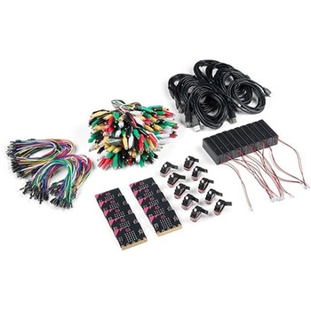 SparkFun Educator Lab Pack for micro:bit v2SPARKFUN
¥109,800税込¥120,780
1個
33日以内出荷
DescriptionThe micro:bit v2 Educator's Lab Pack includes 10 micro:bit v2 boards and everything you need to get you started with the new learning platform. The Lab Pack has everything you need, including micro:bits, cables, battery packs and a few parts to experiment with. This package provides an easy way to introduce your students to the micro:bit without any difficulty or parts hunting.SparkFun packages everything educators need to get started with the micro:bit in a variety of classroom settings and learning environments. The hardware boards, cables and extra parts come pre-packaged. Examples and curriculum materials are available from SparkFun and micro:bit, as well as from other educators involved in this growing maker education movement.Lab Packs are your classroom entry point. By combining our kits, popular boards and other educational tools with support materials(to be updated), SparkFun brings all the power of the open source community to the classroom. We've also updated the battery pack to be closer to what is in other micro:bit kits. It now requires 2xAAA batteries.The micro:bit is a pocket-sized computer that lets you get creative with digital technology. Between the micro:bit and our shield-like bit boards you can do almost anything while coding, customizing and controlling your micro:bit from almost anywhere! You can use your micro:bit for all sorts of unique creations, from robots to musical instruments and more. At half the size of a credit card, this versatile board has vast potential!FeaturesMicro:bit 2.0:64 MHz Arm Cortex-M4 with FPU512KB Flash128KB RAM5x5 Red LED ArrayTwo Programmable Buttons, one touch sensitive logoMEMS microphone and LED indicatorOnboard Light, Compass, Accelerometer, Temp Sensors and Speaker2.4 Ghz Micro:bit Radio/BLE 5.0 Smart Antenna25-pin Edge Connector4 dedicated GPIO, PWM, i2c, SPI, and ext. powerThree Digital/Analog Input/Output RingsTwo Power Rings --- 3V and GNDDedcated I2C bus for peripheralsMicroUSB Connector(5V)JST-PH Battery Connector(NotJST-XH)(3V)Power/reset Button with Status LED200 mA available for accessoriesProgram with C++, MakeCode, Python, Scratch
アズワン品番67-0424-92
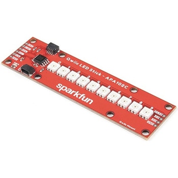 SparkFun Qwiic LED Stick - APA102CSPARKFUN
¥3,500税込¥3,850
1個
33日以内出荷
DescriptionThe SparkFun Qwiic LED Stick features ten addressable APA102 LEDs, making it easy to add full color LED control using I2C. Write to individual LEDs to display a count in binary, or write to the whole strip for cool lighting effects. You can even add more LEDs to the end if you need to. We've written an Arduino library and Python package that take care of the I2C and communication to the LEDs so all you have to do is decide what color each LED should be.The LED Stick has a default I2C address of 0x23 but can be changed with a simple command, allowing you to control up to 100 LEDs(10 Qwiic LED Sticks)on a single bus! The address can also be changed to 0x22 by closing the solder jumper on the back of the board.This board is one of our many Qwiic compatible boards! Simply plug and go. No soldering, no figuring out which is SDA or SCL, and no voltage regulation or translation required!Warning:Using a lot of LEDs can draw a lot of current. Make sure to consider the power limits of your setup. If you expect your LED chain to draw more than 600mA of current, connect your external supply directly to VLED. Closing the jumper from VLED to VCC will add a 4.7uF decoupling capacitor.The SparkFun Qwiic Connect System is an ecosystem of I2C sensors, actuators, shields and cables that make prototyping faster and less prone to error. All Qwiic-enabled boards use a common 1mm pitch, 4-pin JST connector. This reduces the amount of required PCB space, and polarized connections mean you can't hook it up wrong.Get Started with the Qwiic LED Stick GuideFeatures10x APA102C addressable LEDs driven by an ATTiny85Default I2C Address:0x23(Adjustable to 0x22 via Jumper)2x Qwiic Connectors
アズワン品番67-0421-83