「as-i」の検索結果


Description。Cherry MX Keyswitches are top-of-the-line mechanical keyboard switches. They're satisfyingly "clicky", reliable up to tens-of-millions of key presses, and a standard in gaming and programming keyboards across the globe. With the SparkFun Cherry MX Switch Breakout we have made the switches more easily adaptable to breadboard or perfboard-based projects. The Cherry MX Switch Breakout is a perfect prototyping tool for projects ranging from a single-key user-input to fully-custom 101-key keyboards.。In addition to breaking out the switch contacts to breadboard-compatible headers, the Cherry MX Switch Breakout also provides access to an optional switch-mounted LED. Plus, the pin break-outs are designed with keyboard matrix-ing in mind, so you can interconnect as many boards as you'd like into a row-column configuration, keeping the I/O-pin requirements as low as possible.。Note:If you are looking for a Cherry MX Switch to use with this breakout, we've got you covered! CLICK HERE!。Get Started with the Cherry MX Switch Guide。Features。Support for 3mm LED。Footprint for LED current-limiting resistor。Footprint for switch-isolating diode。Chain-able in row/column matrices。Designed to match standard key spacing and keyboard row offsets
アズワン品番67-0419-91
1個
¥449
税込¥494
翌々日出荷

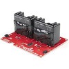
Description。The SparkFun Qwiic Dual Solid State Relay is a power delivery board that allows users to switch two AC loads from a low power microcontroller using the SparkFun Qwiic connect system. The board features two 25A/250VAC solid state relays that utilize the Zero Cross Trigger method so you can toggle two loads on a 60Hz AC carrier signal on and off up to 120 times per second!。An ATTiny84 acts as the "brain" of the SparkFun Qwiic Dual Solid Relay to accept I2C commands to toggle the two relays as well as a few other special commands. The I2C address of the ATtiny84A is software configurable so, if you have a seriously big power project in mind, you could daisy chain over 100 Qwiic Dual Solid State Relays.。Messing with such high voltage is dangerous! We've included many safety precautions onto the PCB including ground isolation between the relay and other circuitry and a milled out area isolating each side of AC. However, with all the safety precautions included with the SparkFun Qwiic Dual Solid State Relay, this is still a power accessory for users who are experienced around, and knowledgeable about high AC voltage. If you're not comfortable with handling AC voltage in this way, you may want to check out the IoT Power Relay instead.。Note:The relays are rated for a max of 25A with forced air cooling. If you do not have forced air cooling, 10A max through the relays is recommended.。The SparkFun Qwiic connect system is an ecosystem of I2C sensors, actuators, shields and cables that make prototyping faster and less prone to error. All Qwiic-enabled boards use a common 1mm pitch, 4-pin JST connector. This reduces the amount of required PCB space, and polarized connections mean you can't hook it up wrong.。Get Started with the SparkFun Qwiic Dual Solid State Relay Guide。Features。Operating Voltage:2.5-3.6V(3.3V recommended)。I2C Address:0x0A(Default)0x0B(Alternate via jumper select)。Load Voltage Range:12-280VAC。Max Current(Through Relay):25A(240VAC with forced air cooling)。Zero Cross Trigger。Normally Open Circuit Only。2x Qwiic Connector
アズワン品番67-0421-58
1個
¥37,980
税込¥41,778
翌々日出荷

Description。The SparkFun moto:bit is a fully loaded "carrier" board for the micro:bit that, when combined with the micro:bit, provides you with a fully functional robotics platform. The moto:bit offers a simple, beginner-friendly robotics controller capable of operating a basic robotics chassis. Onboard each moto:bit are multiple I/O pins, as well as a vertical Qwiic connector, capable of hooking up servos, sensors and other circuits. At the flip of the switch you can get your micro:bit moving!。The moto:bit connects to the micro:bit via an updated SMD, edge connector at the top of the board, making setup easy. This creates a handy way to swap out micro:bits for programming, while still providing reliable connections to all of the different pins on the micro:bit. We have also included a basic barrel jack on the moto:bit that is capable of providing power to anything you connect to the carrier board.。The micro:bit is a pocket-sized computer that lets you get creative with digital technology. Between the micro:bit and our shield-like bit boards you can do almost anything while coding, customizing and controlling your micro:bit from almost anywhere! You can use your micro:bit for all sorts of unique creations, from robots to musical instruments and more. At half the size of a credit card, this versatile board has vast potential!。Note:The SparkFun moto:bit does。NOT。include a micro:bit board. The micro:bit will need to be purchased separately.。Get started with the moto:bit Guide。Features。More reliable Edge connector for easy use with the micro:bit。Full H-Bridge for control of two motors。Control servo motors。Vertical Qwiic Connector。I2C port for extending functionality。Power and battery management onboard for the micro:bit
アズワン品番67-0422-89
1個
¥6,798
税込¥7,478
翌々日出荷

Description。The SparkFun Alphanumeric Display Arduino library makes printing strings to the display as easy as calling the print()function. With this library, you'll be able to send I2C commands to the VK16K33 LED driver chip to light up segments(including the decimal point or colon)and even scroll your string across the display. You can download the library through the Arduino library manager by searching 'SparkFun Alphanumeric Display' or you can get the GitHub repo as a .zip file and install the library from there.。The SparkFun Qwiic Connect System is an ecosystem of I2C sensors, actuators, shields and cables that make prototyping faster and less prone to error. All Qwiic-enabled boards use a common 1mm pitch, 4-pin JST connector. This reduces the amount of required PCB space, and polarized connections mean you can't hook it up wrong.。Get Started with the Qwiic Alphanumeric Display Hookup Guide。Features。Operating Voltage:3.3V。Integrated RC oscillator。Maximum display segment numbers:128 patterns。13×3 matrix key scan circuit。16-step dimming circuit。I2C Addresses:0x70(0x71, 0x72, 0x73)。2x Qwiic connectors。2x Wall Mounting Points
アズワン品番67-0421-61
1個
¥2,098
税込¥2,308
翌々日出荷

Description。The SparkFun Alphanumeric Display Arduino library makes printing strings to the display as easy as calling the print()function. With this library, you'll be able to send I2C commands to the VK16K33 LED driver chip to light up segments(including the decimal point or colon)and even scroll your string across the display. You can download the library through the Arduino library manager by searching 'SparkFun Alphanumeric Display' or you can get the GitHub repo as a .zip file and install the library from there.。The SparkFun Qwiic Connect System is an ecosystem of I2C sensors, actuators, shields and cables that make prototyping faster and less prone to error. All Qwiic-enabled boards use a common 1mm pitch, 4-pin JST connector. This reduces the amount of required PCB space, and polarized connections mean you can't hook it up wrong.。Get Started with the Qwiic Alphanumeric Display Hookup Guide。Features。Operating Voltage:3.3V。Integrated RC oscillator。Maximum display segment numbers:128 patterns。13×3 matrix key scan circuit。16-step dimming circuit。I2C Addresses:0x70(0x71, 0x72, 0x73)。2x Qwiic connectors。2x Wall Mounting Points
アズワン品番67-0421-62
1個
¥2,098
税込¥2,308
翌々日出荷

Description。The SparkFun Alphanumeric Display Arduino library makes printing strings to the display as easy as calling the print()function. With this library, you'll be able to send I2C commands to the VK16K33 LED driver chip to light up segments(including the decimal point or colon)and even scroll your string across the display. You can download the library through the Arduino library manager by searching 'SparkFun Alphanumeric Display' or you can get the GitHub repo as a .zip file and install the library from there.。The SparkFun Qwiic Connect System is an ecosystem of I2C sensors, actuators, shields and cables that make prototyping faster and less prone to error. All Qwiic-enabled boards use a common 1mm pitch, 4-pin JST connector. This reduces the amount of required PCB space, and polarized connections mean you can't hook it up wrong.。Get Started with the Qwiic Alphanumeric Display Hookup Guide。Features。Operating Voltage:3.3V。Integrated RC oscillator。Maximum display segment numbers:128 patterns。13×3 matrix key scan circuit。16-step dimming circuit。I2C Addresses:0x70(0x71, 0x72, 0x73)。2x Qwiic connectors。2x Wall Mounting Points
アズワン品番67-0421-64
1個
¥2,098
税込¥2,308
翌々日出荷

Description。The SparkFun Alphanumeric Display Arduino library makes printing strings to the display as easy as calling the print()function. With this library, you'll be able to send I2C commands to the VK16K33 LED driver chip to light up segments(including the decimal point or colon)and even scroll your string across the display. You can download the library through the Arduino library manager by searching 'SparkFun Alphanumeric Display' or you can get the GitHub repo as a .zip file and install the library from there.。The SparkFun Qwiic Connect System is an ecosystem of I2C sensors, actuators, shields and cables that make prototyping faster and less prone to error. All Qwiic-enabled boards use a common 1mm pitch, 4-pin JST connector. This reduces the amount of required PCB space, and polarized connections mean you can't hook it up wrong.。Get Started with the Qwiic Alphanumeric Display Hookup Guide。Features。Operating Voltage:3.3V。Integrated RC oscillator。Maximum display segment numbers:128 patterns。13×3 matrix key scan circuit。16-step dimming circuit。I2C Addresses:0x70(0x71, 0x72, 0x73)。2x Qwiic connectors。2x Wall Mounting Points
アズワン品番67-0421-63
1個
¥2,098
税込¥2,308
翌々日出荷

Description。After years of popularity with the XBee Series 1 and XBee Series 2 Pro Modules, we now have the XBee Series 3 Pro which brings the best of both worlds. XBee 3 not only handles 802.15.4, and ZigBee, but also BLE protocols and you can now talk to the modules over UART or SPI as well. With a 300ft indoor range, or 2mile outdoor/line-of-sight range, you can set up a mesh network to talk to or communicate with various devices around your house, work, or other area.。This module has the familiar XBee package while sporting a U.FL connector to add an antenna. You also get a built in microcontroller so you can also configure and program the modules using MicroPython as well as Digi's XCTU software. With a HCS08 CPU running at up to 50.33MHz, 15x digital I/O pins, and 4x 10-bit ADC pins these modules can even hold their own as a microcontroller.。Note:While these are backwards compatible in many ways with the XBee 1s and 2s, they are not completely compatible. Please see documentation for differences if you plan on adding these to an existing project.。Features。RF 250Kbps, Serial 1Mbps。300ft(indoor)to 2 mile(outdoor)range。Transmit power +19dBM @ 135mA。Receiver Sensitivity -103dBm @ 15mA。4x 10-bit ADC inputs。15x Digital I/O pins。HCS08 CPU at up to 50.33MHz。128/256 bit AES Encryption。2.1V to 3.6V operating voltage。1.7 μA power-down current。Built in RS-485 support。AT command or API frame support。FCC Certified
アズワン品番67-0429-52
1個
¥10,980
税込¥12,078
翌々日出荷

Description。After years of popularity with the XBee Series 1 and XBee Series 2 Pro Modules, we now have the XBee Series 3 Pro which brings the best of both worlds. XBee 3 not only handles 802.15.4, and ZigBee, but also BLE protocols and you can now talk to the modules over UART or SPI as well. With a 300ft indoor range, or 2mile outdoor/line-of-sight range, you can set up a mesh network to talk to or communicate with various devices around your house, work, or other area.。This module has the familiar XBee package while sporting a connector to add an RP-SMA antenna. You also get a built in microcontroller so you can also configure and program the modules using MicroPython as well as Digi's XCTU software. With a HCS08 CPU running at up to 50.33MHz, 15x digital I/O pins, and 4x 10-bit ADC pins these modules can even hold their own as a microcontroller.。Note:While these are backwards compatible in many ways with the XBee 1s and 2s, they are not completely compatible. Please see documentation for differences if you plan on adding these to an existing project.。Features。RF 250Kbps, Serial 1Mbps。300ft(indoor)to 2mile(outdoor)range。Transmit power +19dBM @ 135mA。Receiver Sensitivity -103dBm @ 15mA。4x 10-bit ADC inputs。15x Digital I/O pins。HCS08 CPU at up to 50.33MHz。128/256 bit AES Encryption。2.1V to 3.6V operating voltage。1.7 μA power-down current。Built in RS-485 support。AT command or API frame support。FCC Certified
アズワン品番67-0429-54
1個
¥9,898
税込¥10,888
33日以内出荷

Description。The Si7021 is a low-cost, easy-to-use, highly accurate, digital humidity and temperature sensor. This sensor is ideal for environmental sensing and data logging and perfect for build a weather stations or humidor control system. All you need are two lines for I2C communication, and you'll have relative humidity readings and very accurate temperature readings as a bonus!。There are only four pins that need to be hooked up in order to start using this sensor in a project. One for VCC, one for GND, and two data lines for I2C communication. This breakout board has built-in 4.7KΩ pullup resistors for I2C communications. If you're hooking up multiple I2C devices on the same bus, you may want to disable these resistors.。Features。0.6"×0.6"
アズワン品番67-0430-34
1個
¥5,698
税込¥6,268
33日以内出荷

Description。We are quite familiar with seven-segment displays. We see them on our alarm clocks, ovens, and microwaves. By adding more segments to each digit you can display more than just numbers! Introducing the brand new SparkFun Qwiic Alphanumeric Display. These white fourteen-segment digits allow you display all sorts of numbers, characters, and symbols. With Qwiic, simply plug it in and go. No soldering, no figuring out which is SDA or SCL, and no voltage regulation or translation required!。The SparkFun Alphanumeric Display Arduino library makes printing strings to the display as easy as calling the print()function. With this library, you'll be able to send I2C commands to the VK16K33 LED driver chip to light up segments(including the decimal point or colon)and even scroll your string across the display. You can download the library through the Arduino library manager by searching 'SparkFun Alphanumeric Display' or you can get the GitHub repo as a .zip file and install the library from there.。The VK16K33 also supports I2C address configuration. Simply close a combination of the address jumpers on the back and you can communicate with up to four displays on the same bus. Our slim board design also features detachable stand off holes, vertical Qwiic connectors, and internal mounting holes.。The SparkFun Qwiic Connect System is an ecosystem of I2C sensors, actuators, shields and cables that make prototyping faster and less prone to error. All Qwiic-enabled boards use a common 1mm pitch, 4-pin JST connector. This reduces the amount of required PCB space, and polarized connections mean you can't hook it up wrong.。Get Started with the Qwiic Alphanumeric Display Hookup Guide。Features。White display。Operating Voltage:3.3V。Integrated RC oscillator。Maximum display segment numbers:128 patterns。13×3 matrix key scan circuit。16-step dimming circuit。I2C Addresses:0x70(0x71, 0x72, 0x73)。2x Qwiic connectors。2x Wall Mounting Points
アズワン品番67-0421-87
1個
¥2,098
税込¥2,308
翌々日出荷

Description。Are you low on I/O? No problem! The SX1509 Breakout is 16-channel GPIO expander with an I2C interface that means with just two wires, your microcontroller can interface with 16 fully configurable digital input/output pins. But the SX1509 can do so much more than just simple digital pin control. It can produce PWM signals, so you can dim LEDs. It can be set to blink or even breathe pins at varying rates. This breakout is similar to multiplexer or "mux," in that it allows you to get more IO from less pins. And, with built-in keypad engine, it can interface with up to 64 buttons set up in an 8x8 matrix.。Two headers at the top and bottom of the breakout board function as the input and control headers to the board. This is where you can supply power to the SX1509, and where your I2C signals SDA and SCL will terminate. GPIO and power buses are broken out in every-which direction, and configurable jumpers cover most of the rest of the board.。Since the I/O banks can operate between 1.2V and 3.6V(5.5V tolerant)independent of both the core and each other, this device can also work as level-shifter. The SX1509 breakout makes it easy to prototype so you can add more I/O onto your Arduino or I/O limited controller. We've even spun up an Arduino Library to get you started!。Features。Enable Direct Level Shifting Between I/O Banks and Host Controller。5.5V Tolerant I/Os, Up to 15mA Output Sink on All I/Os。Integrated LED Driver with Intensity Control。On-Chip Keypad Scanning Engine Supports Up to 8x8 Matrix(64 Keys)。16 Channels of True Bi-directional Style I/O。400kHz I2C Compatible Slave Interface
アズワン品番67-0419-88
1個
¥1,598
税込¥1,758
翌々日出荷

Description。The LIDAR-Lite v4 LED sensor is the next step in the LIDAR-Lite line. A small, lightweight, low-power optical ranging sensor. It's the first to incorporate ANT profile wireless networking technology into an optical sensor. Its built-in nRF52840 processor means that developers can create custom applications, or be operated as a stand-alone device right out of the box by using the preloaded stock application.。Like the LIDAR-Lite v3 and LIDAR-Lite v3HP sensors; it can also be directly connected to an external micro-controller running a custom user application. As such, it provides a highly adaptable option for OEM and maker applications in robotics, Internet of Things, and unmanned vehicles ― or any application where an ultrasonic sensor might otherwise be used. It's perfect as the basic building block for applications where wireless capabilities, small size, light weight, low power consumption and high performance are important factors in a short-range, 10-meter, optical distance measuring sensor.。The LIDAR-Lite v4 requires an external 5VDC power source and soldering is required. This Time-of-Flight ranging module uses a LED and optics for ranging. It does not use a laser; therefore, it is inherently eye-safe under normal usage.。Features。Resolution:1 cm。Measurement repeatability:As measured indoors to a 90% reflective target。1 cm is equivalent to 1 standard deviation。Using "high accuracy" mode, with averaging:+/- 1 cm to 2 meters。+/- 2 cm to 4 meters。+/- 5 cm to 10 meters。Range:5 cm to 10 meters(as measured from back of unit)。Update rate:I2C = >200 Hz typical。ANT(R)= up to 200 Hz to a 90% target indoors at 2m in normal operating mode。Interface:I2C or ANT; user configurable for SPI using the Nordic SDK。Power(operating voltage):4.75 - 5.25 VDC。Current consumption:2mA idle, 85mA during acquisition。Operating temperature:-20 to 60° C。LED wavelength:940 nm。Beam divergence:4.77°。Optical aperture:14.9 mm。Unit size(HxWxD):2.1"×0.8"×0.9"(52.2×21.2×24.0 mm)。Weight:14.6 g(0.5 oz)
アズワン品番67-0427-09
1個
¥18,980
税込¥20,878
翌々日出荷

Description。Note - Please read before purchasing!:The SparkFun LTE GNSS Breakout - SARA-R5 uses the "00B" product version of the SARA-R5 module(specifically the SARA-R510M8S-00B-00). LTE NB-IoT Radio Access Technology, and the LTE FDD bands:66, 71, 85 are not supported by this version. Refer to the SARA-R5 datasheet for more information.。The SparkFun SARA-R5 LTE GNSS Breakout is a robust development tool for u-blox's impressive SARA-R510M8S module. The SARA-R510M8S combines u-blox's UBX-R5 cellular chipset with their M8 GNSS receiver chipset to provide a 5G-Ready wireless IoT device complete with positioning data all on a single chip. As an asset tracker, the LTE GNSS Breakout offers Secure Cloud LTE-M communication for multi-regional use and has an integrated u-blox M8 GNSS receiver for accurate positioning information.。The UBX-R5 chipset supports many different forms of data communication from full TCP/IP sockets and packet switched data, through HTTP Get/Put/Post, FTP(the SARA has a built-in file system), Ping, to good old SMS text messaging! The built-in u-blox M8 GNSS receiver provides accurate and reliable positioning with a separate GNSS antenna interface for an external antenna. Both the GNSS antenna and LTE connections are made via a pair of SMA connectors.。This breakout routes nearly all of the functional pins on the SARA-R510M8S module to user interfaces(USB or plated-through hole)so you can take full advantage of all of the features available on this impressive LTE/GNSS module. The SARA-R5's UART interface can be configured into one of five variants, providing connectivity over one or two UARTs. A separate USB port provides access to the SARA's trace log for diagnostic purposes. This breakout provides access to all three interfaces(UART1, UART2 and SARA Diag)via three separate USB-C connections. All eight 3.3V serial signals are available on a 0.1"-pitch breakout header. Separate 0.1"-pitch headers break out the SARA's I2C bus, power pins as well as GPIO pins for various functionalities.。Get Started with the SARA-R5 LTE GNSS Breakout Guide。Features。u-blox SARA-R510M8S module providing Secure Cloud LTE-M data communication for multi-regional use。Please check that your service provider offers LTE-M coverage for your area before purchasing。Integrated u-blox M8 GNSS receiver for accurate positioning information。Nano SIM socket。Separate, robust SMA connections for LTE and GNSS antennas。Switchable 3.3V power for an active GNSS antenna。USB-C connectivity。LED indicators for:Power(VIN and 3.3V)。SARA-R5 on。Network indicator。GNSS timing pulse(1PPS)。3.3V plated through-hole(PTH)pins for:SARA on。Network indicator。UART1。GNSS timing pulse(1PPS)。I2C bus
アズワン品番67-0423-92
1個
¥33,980
税込¥37,378
翌々日出荷

Description。Buttons are an easy and tactile way to interface with your project, but why would you want to deal with debouncing, polling, and wiring up pull-up resistors? The Qwiic Button with built-in green LED simplifies all of those nasty worries away into an easy to use I2C device! Utilizing our Qwiic Connect System, using the button is as simple as connecting cable and loading up some pre-written code!。If you need multiple buttons for your project, fear not! Each button has configurable I2C address, so you can daisy-chain multiple buttons over Qwiic and still address each one individually. We've got an example in our Arduino library that provides super-easy way to configure your Qwiic Button to whatever I2C address you desire. You can download the library through the Arduino library manager by searching 'SparkFun Qwiic Button' or you can get the GitHub repo as .zip file and install the library from there.。In addition to handling blinking and debouncing, the Qwiic Button has configurable interrupts that can be configured to activate upon button press or click. We've also taken the liberty of implementing FIFO queue onboard the Qwiic Button where it keeps an internal record of when the button was pressed. This means that code on your microcontroller need not waste valuable processing time checking the status of the button but instead can run small function whenever the button is pressed or clicked! For more information on interrupts check out our guide here!。The SparkFun Qwiic Connect System is an ecosystem of I2C sensors, actuators, shields and cables that make prototyping faster and less prone to error. All Qwiic-enabled boards use common 1mm pitch, 4-pin JST connector. This reduces the amount of required PCB space, and polarized connections mean you can't hook it up wrong.。Get Started with the SparkFun Qwiic Button Guide。Features。12mm Green LED Button rated for 50mA。Built in LED can be configured for your desired level of blinkiness!。Each button has configurable I2C address。Configurable interrupts check out our guide here!。FIFO queue。Don't like the color green? Check out the SparkFun Qwiic Button Breakout and add another colored button!。Red LED Tactile Button。Blue LED Tactile Button。Green LED Tactile Button。White LED Tactile Button
アズワン品番67-0420-14
1個
¥1,298
税込¥1,428
翌々日出荷

。Description。The HM01B0 from Himax Imaging is an ultra low power CMOS Monochrome Image Sensor that enables the integration of an "Always On" camera for computer vision applications such as gestures, intelligent ambient light and proximity sensing, tracking and object identification. The sensor allows the sensor to consume very low power of <2mW at QVGA 30FPS. This low power consumption and vision applications camera comes with a ribbon cable that mates to the camera connector populated on the following products:MicroMod Machine Learning Carrier Board。Artemis Development Kit。Edge Development Board - Apollo3 Blue。The HM01B0 contains 320×320 pixel resolution and supports a 320×240 window mode which can be readout at a maximum frame rate of 60FPS, and a 2×2 monochrome binning mode with a maximum frame rate of 120FPS. The video data is transferred over a configurable 1bit, 4bit or 8bit interface with support for frame and line synchronization. The sensor integrates black level calibration circuit, automatic exposure and gain control loop, self-oscillator and motion detection circuit with interrupt output to reduce host computation and commands to the sensor to optimize the system power consumption.。Features。Image Sensor。Ultra Low Power Image Sensor(ULPIS)designed for Always On vision devices and applications。High sensitivity 3.6μ BrightSenseTM pixel technology。320×320 active pixel resolution with support for QVGA window, vertical flip and horizontal mirror readout。Programmable black level calibration target, frame size, frame rate, exposure, analog gain(up to 8x)and digital gain(up to 4x)。Automatic exposure and gain control loop with support for 50 / 60Hz flicker avoidance。Flexible 1bit, 4bit and 8bit video data interface with video frame and line sync。Motion Detection circuit with programmable ROI and detection threshold with digital output to serve as an interrupt。On-chip self oscillator。I2C 2-wire serial interface for register access。High CRA for low profile module design。Sensor Parameters。Active Pixel Array 320×320。Pixel Size 3.6 μm×3.6 μm。Full Image Area 1152 μm×1152 μm。Diagonal(Optical Format)1.63 mm(1/11″)。Scan Mode:Progressive。Shutter Type:Electronic Rolling Shutter。Frame Rate MAX 51 fps @ 320×320, 60 fps @ 320×240(QVGA)。CRA(maximum)30℃。Sensor Specifications。Supply Voltage:Analog - 2.8 V, Digital - 1.5V(Internal LDO:1.5V - 2.8V), I/O - 1.5 - 2.8V。Input Reference Clock:3 - 50 MHz。Serial Interface(I2C):2-wire, 400 KHz max.。Video Data Interface:1b, 4b, 8b with frame / line SYNC。Output Clock Rate MAX:50 MHz for 1bit, 12.5 MHz for 4bit, 6.25 MHz for 8bit。Est. Power Consumption(include IO with 5pF load):QVGA 60FPS(Typical)<4 mW。QVGA 30FPS(Typical)<2 mW
アズワン品番67-0427-08
1個
¥2,998
税込¥3,298
翌々日出荷

Description。We all like to know the temperature, right? Well, with the SparkFun TMP102 Digital Temperature Sensor, we've made it just about as easy as it gets. Based on the original Digital Temperature Sensor Breakout TMP102, we've added Qwiic connectors to bring this board into our plug-and-play Qwiic Ecosystem and added an address jumper instead of breaking out the address pin. However, we still have broken out 0.1"-spaced pins in case you prefer to use breadboard.。The TMP102 itself is an easy-to-use digital temperature sensor from Texas Instruments. While some temperature sensors use an analog voltage to represent the temperature, the TMP102 uses the I2C bus of the Arduino to communicate the temperature.。The TMP102 is capable of reading temperatures to resolution of 0.0625℃, and is accurate up to 0.5℃. The breakout has built-in 4.7kΩ pull-up resistors for I2C communications and runs from 1.4V to 3.6V. I2C communication uses an open drain signaling, so there is no need to use level shifting.。The SparkFun Qwiic Connect System is an ecosystem of I2C sensors, actuators, shields and cables that make prototyping faster and less prone to error. All Qwiic-enabled boards use common 1mm pitch, 4-pin JST connector. This reduces the amount of required PCB space, and polarized connections mean you can't hook it up wrong.。Get Started with the Qwiic TMP102 Digital Temperature Sensor Guide。Features。Uses the I2C interface。I2C Address:0x48 by default。(Three additional addresses available, as well)。12-bit, 0.0625℃ resolution。Typical temperature accuracy of ±0.5℃。3.3V sensor。Supports up to four TMP102 sensors on the I2C bus at time。2x Qwiic Connectors
アズワン品番67-0427-17
1個
¥1,498
税込¥1,648
翌々日出荷

Description。The SparkFun BME280 Atmospheric Sensor Breakout is the easy way to measure barometric pressure, humidity, and temperature readings all without taking up too much space. Basically, anything you need to know about atmospheric conditions you can find out from this tiny breakout. The BME280 Breakout has been design to be used in indoor/outdoor navigation, weather forecasting, home automation, and even personal health and wellness monitoring.。The on-board BME280 sensor measures atmospheric pressure from 30kPa to 110kPa as well as relative humidity and temperature. The breakout provides a 3.3V SPI interface, a 5V tolerant I2C interface(with pull-up resistors to 3.3V), takes measurements at less than 1mA and idles less than 5μA. The BME280 Breakout board has 10 pins, but no more than six are used at a single time. The left side of the board provide power, ground, and I2C pins. The remaining pins which provide SPI functionality and have another power and ground, are broken out on the other side.。Note:The breakout does NOT have headers installed and will need to purchased and soldered on yourself. Check the。Recommended Products。section below for the type of headers we use in the Hookup Guide!。Features。Operation Voltage:3.3V。I2C SPI Communications Interface。Temp Range:-40C to 85C。Humidity Range:0 - 100% RH, =-3% from 20-80%。Pressure Range:30,000Pa to 110,000Pa, relative accuracy of 12Pa, absolute accuracy of 100Pa。Altitude Range:0 to 30,000 ft(9.2 km), relative accuracy of 3.3 ft(1 m)at sea level, 6.6(2 m)at 30,000 ft.。Incredibly Small
アズワン品番67-0426-57
1個
¥5,198
税込¥5,718
翌々日出荷

Description。The SparkFun Multiplexer Breakout provides access to all pins and features of the 74HC4051, an 8-channel analog multiplexer/demultiplexer. The 74HC4051 allows you to turn four I/O pins into eight multifunctional, individually selectable signals, which can be used to do everything from driving eight LEDs to monitoring eight potentiometers.。The 74HC4051 can function as either a multiplexer or a demultiplexer, and it features eight channels of selectable inputs/outputs. The routing of common signal to independent I/O is set by digitally controlling three select lines, which can be set either high or low into one of eight binary combinations.。One half of the board breaks out the control signals(E, S0-S2)and common input/output(Z). The other side provides access to all eight independent I/O's(Y0-Y7). Both sides include supply and ground connections(VCC, VEE, GND).。Get Started with the 74HC4051 Breakout Guide。Features。Switches analog or digital signals。8 channels controlled by 3 select inputs。Wide voltage supply range:2 -- 10V。Bipolar supply support(e.g., ±5V)。Optional enable input。Breadboard compatible breakout
アズワン品番67-0419-95
1個
¥639
税込¥703
4日以内出荷

Description。The SparkFun ZOE-M8Q GPS Breakout is a high accuracy, miniaturized, GPS board that is perfect for applications that don't possess a lot of space. The on-board ZOE-M8Q is a 72-channel GNSS receiver, meaning it can receive signals from the GPS, GLONASS, BeiDou, and Galileo constellations. This increases precision and decreases lock time and thanks to the onboard rechargable battery you'll have backup power enabling the GPS to get a hot lock within seconds! Additionally, this u-blox receiver supports I2C(u-blox calls this Display Data Channel)which made it perfect for the Qwiic compatibility so we don't have to use up our precious UART ports. Utilizing our handy Qwiic system, no soldering is required to connect it to the rest of your system. However, we still have broken out 0.1"-spaced pins in case you prefer to use a breadboard.。U-blox based GPS products are configurable using the popular, but dense, windows program called u-center. Plenty of different functions can be configured on the ZOE-M8Q:baud rates, update rates, geofencing, spoofing detection, external interrupts, SBAS/D-GPS, etc. All of this can be done within the SparkFun Arduino Library. We've also made sure to configure the UART pin grouping on the breakout to an industry standard to insure that it easily connects to a Serial Basic.。The SparkFun ZOE-M8Q GPS Breakout is also equipped with an on-board rechargeable battery that provides power to the RTC on the ZOE-M8Q. This reduces the time-to-first fix from a cold start(~30s)to a hot start(~1s). The battery will maintain RTC and GNSS orbit data without being connected to power for up to five hours. Since the ZOE-M8Q is a tiny GPS receiver and to minimize its footprint, we've added a U.FL connector to allow the use of both large standard ceramic antennas as well as very small chip scale antennas.。Note:The I2C address of the ZOE-M8Q is 0x42 and is software configurable. A multiplexer/Mux is required to communicate to multiple ZOE-M8Q sensors on a single bus. If you need to use more than one ZOE-M8Q sensor consider using the Qwiic Mux Breakout.。The SparkFun Qwiic Connect System is an ecosystem of I2C sensors, actuators, shields and cables that make prototyping faster and less prone to error. All Qwiic-enabled boards use a common 1mm pitch, 4-pin JST connector. This reduces the amount of required PCB space, and polarized connections mean you can't hook it up wrong.。The ZOE-M8Q GPS Breakout can also be automatically detected, scanned, configured, and logged using the OpenLog Artemis datalogger system. No programming, soldering, or setup required!。Get Started With the SparkFun ZOE-M8Q Hookup Guide。Features。72-Channel GNSS Receiver。2.5m Horizontal Accuracy。18Hz Max Update Rate。Time-To-First-Fix:Cold:26s。Hot:1s。Max Altitude:50,000m。Max G:≦4。Max Velocity:500m/s。Velocity Accuracy:0.05m/s。Heading Accuracy:0.3 degrees。Time Pulse Accuracy:30ns。3.3V VCC and I/O。Current Consumption:~29mA Tracking GPS+GLONASS。Software Configurable。Geofencing。Odometer。Spoofing Detection。External Interrupt。Pin Control。Low Power Mode。Many others!。Supports NMEA, UBX, and RTCM protocols over UART or I2C interfaces
アズワン品番67-0423-76
1個
¥11,980
税込¥13,178
翌々日出荷

。Description。Need to keep track of the airflow in your data center or around your servers? How about making sure your HVAC and air control systems are functioning at full capacity? Well, the new SparkFun FS3000-1005 Air Velocity Sensor Breakout can help you with all that and more! It's super easy and super quick(Qwiic!)to hook up.。This breakout board is focused around Renesas' FS3000-1005, a surface-mount air velocity module with a range of 0-7.2m/s(0-16.2mph). It utilizes a MEMS thermopile-based sensor, features a digital output with 12-bit resolution and comprises a "solid" thermal isolation technology and silicon carbide coating to protect it from abrasive wear and water condensation.。We've written an Arduino library to help you get started quickly. You can download the library through the Arduino library manager by searching 'SparkFun Air Velocity' or you can get the GitHub repo as a .zip file and install the library from there.。The SparkFun Qwiic Connect System is an ecosystem of I2C sensors, actuators, shields and cables that make prototyping faster and less prone to error. All Qwiic-enabled boards use a common 1mm pitch, 4-pin JST connector. This reduces the amount of required PCB space, and polarized connections mean you can't hook it up wrong.。Get Started with the Qwiic Air Velocity Sensor Breakout。Features。I2C address:0x28。Air flow speed:0 - 7.23 m/sec(0 - 16.17mph)。Accuracy:5 % of full scale flow range。12-bit resolution。Input Voltage:2.7-3.3V。Average current draw:10mA
アズワン品番67-0427-58
1個
¥15,980
税込¥17,578
翌々日出荷

Description。The SparkFun Qwiic HAT for Raspberry Pi is the quickest and easiest way to enter into SparkFun's Qwiic ecosystem while still using that Raspberry Pi that you've come to know and love. The Qwiic HAT connects the I2C bus(GND, 3.3V, SDA and SCL)on your Raspberry Pi to an array of Qwiic connectors on the HAT. Since the Qwiic system allows for daisy chaining boards with different addresses, you can stack as many sensors as you'd like to create a tower of sensing power!。The Qwiic Pi HAT has four Qwiic connect ports, all on the same I2C bus. In addition, many of the useful GPIO pins on the Raspberry Pi are broken out. This HAT is compatible with any Raspberry Pi that utilizes the standard 2x20 GPIO header. It has been designed to sit to the side of the Pi, allowing it to work conveniently with a Pi Tin enclosure to connect boards to the Qwiic ports.。Note:。There is a small silk error that has reversed the SDA and SCL. This is simply a cosmetic mix-up and will not impact any function with this board.。The SparkFun Qwiic Connect System is an ecosystem of I2C sensors, actuators, shields and cables that make prototyping faster and less prone to error. All Qwiic-enabled boards use a common 1mm pitch, 4-pin JST connector. This reduces the amount of required PCB space, and polarized connections mean you can't hook it up wrong.。Get Started with the SparkFun Qwiic Pi HAT Guide。Features。4x Qwiic Connection Ports。Select GPIO Pins Broken Out。Pi Tin Compatibility
アズワン品番67-0422-50
1個
¥1,498
税込¥1,648
翌々日出荷

Description。Leveraging the ultra powerful Artemis Module, the SparkFun MicroMod Artemis Processor is the brain board of your dreams. With a Cortex-M4F with BLE 5.0 running up to 96MHz and with as low power as 6uA per MHz(less than 5mW), the M.2 MicroMod connector allows you to plug in a MicroMod Carrier Board with any number of peripherals. Let's have a look at what this processor board has to offer! If you need Machine Learning capabilities, Bluetooth, I2C functionality to connect to all our amazing Qwiic boards, and more the Artemis Processor is the perfect choice for your MicroMod Carrier Board.。At the heart of SparkFun's Artemis Module is Ambiq Micro's Apollo3 processor, whose ultra-efficient ARM Cortex-M4F processor is spec'd to run TensorFlow Lite using only 6uA/MHz. We've routed two I2C buses, eight GPIO, dedicated digital, analog, and PWM pins, multiple SPI as well as QuadSPI, and Bluetooth to boot. You really can't go wrong with this processor. Grab one today, pick up a compatible carrier board, and get hacking!。MicroMod is a modular interface ecosystem that connects a microcontroller "processor board" to various "carrier board" peripherals. Utilizing the M.2 standard, the MicroMod standard is designed to easily swap out processors on the fly. Pair a specialized carrier board for the project you need with your choice of compatible processor!。Get Started with the MicroMod Artemis Processor Guide。Features。Artemis General Features。1M Flash / 384k RAM。48MHz / 96MHz turbo available。6uA/MHz(operates less than 5mW at full operation)。48 GPIO - all interrupt capable。31 PWM channels。Built in BLE radio and antenna。10 ADC channels with 14-bit precision with up to 2.67 million samples per second effective continuous, multi-slot sampling rate。2 channel differential ADC。2 UARTs。6 I2C buses。6 SPI buses。2/4/8-bit SPI bus。PDM interface。I2S Interface。Secure 'Smart Card' interface。FCC/IC/CE Certified(ID Number 2ASW8-ART3MIS)。Specific Peripherals made available on MicroMod Artemis:1x USB dedicated for programming and debug。1x UART with flow control。2x I2C。1x SPI。1x Quad-SPI。8x Fast GPIO。2x Digital Pins。2x Analog Pins。2x PWM。1x Differential ADC pair。Status LED。VIN Level ADC。Additional peripherals are available but are shared on dedicated MicroMod pins.
アズワン品番67-0423-05
1個
¥4,398
税込¥4,838
翌々日出荷
関連キーワード