「atp」の検索結果
関連キーワード


1個
¥7,498
税込¥8,248
33日以内出荷

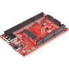
Description。Access all the pins(i.e. ATP)of the MicroMod Processor Boards with the SparkFun MicroMod ATP Carrier Board! This board breaks out the MicroMod Processor Board's pins on the M.2 connector to 0.1" spaced female headers and PTH pads on the edge of the board. This Carrier Board is great if you're interested in testing out different MicroMod Processor Boards for your application.。A modern USB-C connector makes programming easy. In addition to the pins broken out, two separate Qwiic-enabled I2C ports allow you to easily daisy chain Qwiic-enabled devices. We've exposed the SWD pins for more advanced users who prefer to use the power and speed of professional tools. A USB-A connector is provided for Processor Boards that have USB Host support. A backup battery is provided for processor boards with RTC. If you need a "lot" of GPIO with a simple-to-program, ready for market module, the ATP is the fix you need. We've even added a convenient jumper to measure the current consumption for low power testing.。MicroMod is a modular interface ecosystem that connects a microcontroller "processor board" to various "carrier board" peripherals. Utilizing the M.2 standard, the MicroMod standard is designed to easily swap out processors on the fly. Pair a specialized carrier board for the project you need with your choice of compatible processor!。Get Started with the MicroMod ATP Carrier Board Guide。Features。M.2 Connector。Operating Voltage Range。~3.3V to 6.0V(via VIN to AP7361C 3.3V Voltage Regulator)。3.3V(via 3V3)。Ports [1]。1x USB type C。1x USB type A Host。2x Qwiic Enabled I2C。1x CAN。1x I2S。2x SPI。2x UARTs。2x Dedicated Analog Pins。2x Dedicated PWM Pins。2x Dedicated Digital Pins。12x General Purpose Input Output Pins。1x SWD 2x5 header。1mAh battery backup for RTC。Buttons。Reset。Boot。LEDs。Power。3.3V。Phillips #0 M2.5x3mm screw included。[1] Note:Depending on the design of the Processor Board, not all the pins may be accessible.
アズワン品番67-0423-18
1個
¥4,398
税込¥4,838
33日以内出荷

。Description。Think of the RedBoard Artemis as just another Arduino... That has BLE. And one megabyte of flash. And runs at less than 1mA. Oh, and it can run TensorFlow models. Ya, that too. The RedBoard Artemis takes the incredibly powerful Artemis module from SparkFun and wraps it up in an easy to use and familiar Uno footprint. We've written an Arduino core from scratch to make programming the Artemis as familiar as。Serial.begin(9600)。. Time-to-first-blink is less than five minutes.。The RedBoard Artemis has the improved power conditioning and USB to serial that we've refined over the years on our RedBoard line of products. A modern USB-C connector makes programming easy. A Qwiic connector makes I2C easy. The RedBoard Artemis is fully compatible with SparkFun's Arduino core and can be programmed easily under the Arduino IDE. We've exposed the JTAG connector for more advanced users who prefer to use the power and speed of professional tools. We've added a digital MEMS microphone for folks wanting to experiment with always-on voice commands with TensorFlow and machine learning. We've even added a convenient jumper to measure current consumption for low power testing.。With 1MB flash and 384k RAM you'll have plenty of room for your sketches. The on-board Artemis module runs at 48MHz with a 96MHz turbo mode available and with Bluetooth to boot!。The SparkFun RedBoard Artemis is a great platform to 'kick the tires' of this amazing module. If you're interesting in testing out the full capabilities of the SparkFun Artemis module or if you're looking for more compact solution, be sure to checkout our ATP and Nano versions of the Artemis line.。Get Started With the SparkFun Artemis RedBoard Guide。Features。Arduino Uno R3 Footprint。1M Flash / 384k RAM。48MHz / 96MHz turbo available。24 GPIO - all interrupt capable。21 PWM channels。Built in BLE radio。10 ADC channels with 14-bit precision。2 UARTs。6 I2C buses。4 SPI buses。PDM Interface。I2S Interface。Qwiic Connector
アズワン品番67-0422-82
1個
¥5,298
税込¥5,828
33日以内出荷

Description。The SN74HC595N is a simple 8-bit shift register IC. Simply put, this shift register is a device that allows additional inputs or outputs to be added to a microcontroller by converting data between parallel and serial formats. Your chosen microprocessor is able to communicate with the The SN74HC595N using serial information then gathers or outputs information in a parallel(multi-pin)format. Essentially it takes 8 bits from the serial input and then outputs them to 8 pins.。This small DIP packaged IC contains an 8-bit, serial-in parallel-out shift register that feeds an 8-bit D-type storage register with parallel 3-state outputs.。Note:。This is a drop-in replacement for the 74HC595 shift register IC and should function just fine in any application the previous version could.。Get started with the Shift Register Guide。Features。8-Bit Serial-In, Parallel-Out Shift。Wide Operating Voltage Range of 2 V to 6 V。High-Current 3-State Outputs Can Drive Up to 15 LSTTL Loads。Low Power Consumption:80-μA。±6-mA Output Drive at 5 V
アズワン品番67-0420-82
1個
¥219
税込¥241
33日以内出荷

。Description。Arduino is an open-source physical computing platform based on a simple i/o board and a development environment that implements the Processing/Wiring language. Arduino can be used to develop stand-alone interactive objects or can be connected to software on your computer(e.g. Flash, Processing, MaxMSP). The open-source IDE can be downloaded for free(currently for Mac OS X, Windows, and Linux).。The Arduino Mega is a microcontroller board based on the ATmega2560. It has 54 digital input/output pins(of which 14 can be used as PWM outputs), 16 analog inputs, 4 UARTs(hardware serial ports), a 16 MHz crystal oscillator, a USB connection, a power jack, an ICSP header, and a reset button. It contains everything needed to support the microcontroller; simply connect it to a computer with a USB cable or power it with a AC-to-DC adapter or battery to get started.。Never fear for accidental electrical discharge, either since since the Mega also includes a plastic base plate to protect it!。The Mega 2560 R3 also adds SDA and SCL pins next to the AREF.。In addition, there are two new pins placed near the RESET pin. One is the IOREF that allow the shields to adapt to the voltage provided from the board.。The other is a not connected and is reserved for future purposes.。The Mega 2560 R3 works with all existing shields but can adapt to new shields which use these additional pins.。Not sure which Arduino or Arduino-compatible board is right for you? Check out our Arduino Buying Guide!。Features。ATmega2560 microcontroller。Input voltage - 7-12V。54 Digital I/O Pins(14 PWM outputs)。16 Analog Inputs。256k Flash Memory。16Mhz Clock Speed
アズワン品番67-0349-13
1個
¥15,980
税込¥17,578
33日以内出荷

Description。The SparkFun Qwiic Shield for Thing Plus provides you with a quick and easy way to enter into SparkFun's Qwiic ecosystem with your Thing Plus or Feather boards. Since the Thing Plus and Feather footprints are interchangable, you can use th
アズワン品番67-0423-13
1個
¥1,298
税込¥1,428
33日以内出荷

。Description。The Leopard Imaging Camera is a 136° FOV(field of view)wide angle camera module that is great for machine vision applications, and designed specifically to be compatible with the NVIDIA Jetson Nano Developer Kit. This camera incorporates a Sony IMX219 8.08MP color sensor, a fixed focus(M8)lens, and utilizes CSI-2 MIPI 2-lane data output interface.。This is the same camera that we include in the SparkFun Jetbot v2.1 Kit.。Note:SparkFun has not established the compatibility of this camera with Raspberry Pi. We are currently working with the manufacturer, but due to firmware restrictions Leopard cameras do not work with any Raspberry Pi's at this time.。Features。Field of view(FOV):136°。Module size:150mm(L)x 25mm(W)。Sensor type:Sony IMX219 8.08MP color sensor。Active pixels:3280(H)x 2464(V)。Image size:Diagonal 4.60mm(Type 1/4.0)。F/No:2.0(H136)。Focal length:1.58mm(H136)。TV distortion:<-15%(H136)。Focusing range:30cm - Infinity。Lens type:Fixed Focus(M8 lens)。Pixel size:1.12um×1.12um。Data output interface:CSI-2 MIPI 2-lane。IR Cutter Filter:Yes
アズワン品番67-0422-99
1個
¥9,998
税込¥10,998
33日以内出荷

This is the basic L7805 voltage regulator、a three-terminal positive regulator with a 5V fixed output voltage. This fixed regulator provides a local regulation、internal current limiting、thermal shut-down control、and safe area protection for your proje
仕様●入力電圧:35V●出力電圧範囲[V]:5.0V●出力電流[A]:2.2A●機能:正固定●パッケージ:TO-220
アズワン品番67-0452-54
1個
¥229
税込¥252
33日以内出荷

Description。This diode-transistor photocouplers consist of an LED, optically coupled to a high speed photodetector to transmit electrical signals between circuits while still isolating your system from higher voltages. The 6N137 optoisolator is presented in an 8-pin DIP package.。The output features is an open collector and coupler parameters are guaranteed over the temperature range from -40℃~5℃. The internal shield provides a guaranteed Common Mode Transient Immunity(typical)10KV/μs.。Features。High Speed:10MBd。Common Mode Rejection:10KV/μs
アズワン品番67-0421-33
1個
¥319
税込¥351
33日以内出荷

Description。This version of the QRE1113 breakout board features a digital output, using a capacitor discharge circuit to measure the amount of reflection. This tiny board is perfect for line sensing when only digital I/O is available, and can be used
アズワン品番67-0430-22
1個
¥889
税込¥978
33日以内出荷

。Description。The GD25Q40C(4M-bit)Serial flash supports the standard Serial Peripheral Interface(SPI), and supports theDual/Quad SPI:Serial Clock, Chip Select, Serial Data I/O0(SI), I/O1(SO), I/O2(WP#), and I/O3(HOLD#). The Dual I/O data is transferred with speed of 240Mbits/s and the Quad I/O & Quad output data is transferred with speed of 480Mbits/s.。Features。4M-bit Serial Flash。512K-byte。256 bytes per programmable page。Standard, Dual, Quad SPI。High Speed Clock Frequency。120MHz for fast read with 30PF load。Dual I/O Data transfer up to 240Mbits/s。Quad I/O Data transfer up to 480Mbits/s。Software/Hardware Write Protection。Minimum 100,000 Program/Erase Cycles。Data Retention。20-year data retention typical。Single Power Supply Voltage。Full voltage range:2.7~3.6V。Low Power Consumption。1μA typical deep power down current。1μA typical standby current
アズワン品番67-0421-78
1個
¥119
税込¥131
33日以内出荷

Description。The FLIR Lepton(R)2.5 - Thermal Imaging Module is a radiometric-capable long wave infrared(LWIR)camera solution that is smaller than a dime, fits inside a smartphone, and is less expensive than traditional IR cameras. With a focal plane array of 80x60 active pixels, this Lepton easily integrates into native mobile-devices and other electronics as an IR sensor or thermal image sensor. The radiometric Lepton captures accurate, calibrated, and non-contact temperature data in every pixel.。For large quantities:We currently have a limit of one per customer order on the FLIR Lepton 2.5 module due to supply chain issues as a result of COVID-19. If you need to place a distributor order please contact your sales rep and they will assist you. For bulk order for this module please visit our Volume Pricing Page for inquiries of stock. At this time, we cannot guarantee orders for this module but we will do what we can to work with you in fulfilling your request.。Features。Effective Frame Rate:8.6 Hz(commercial application exportable)。Input Clock:25-MHz nominal, CMOS IO Voltage Levels。Output Format:User-selectable 14-bit, 8-bit(AGC applied), or 24-bit RGB(AGC and colorization applied)。Pixel Size:17 μm。Radiometric Accuracy:High gain:Greater of +/- 5℃ or 5%(typical)Low gain:Greater of +/- 10℃ or 10%(typical)。Scene Dynamic Range:-10-140 ℃(high gain); up to 450℃(low gain)typical。Spectral Range:Longwave infrared, 8 μm to 14 μm。Temperature Compensation:Automatic. Output image independent of camera temperature.。Thermal Sensitivity:<50 mK(0.050° C)。Video Data Interface:Video over SPI。Control Port:CCI(I2C-like), CMOS IO Voltage Levels。Package Dimensions - Socket Version(w×l×h):11.8×12.7×7.2 mm。Mechanical Interface:32-pin socket interface to standard Molex(R)socket。Non-Operating Temperature Range:-40 ℃ to +80 ℃。Optimum Temperature Range:-10℃ to +80℃。Shock:1500 G @ 0.4 ms。Array format:80×60, progressive scan。FOV - Diagonal:63.5°。FOV - Horizontal:50°(nominal)。Image Optimization:Factory configured and fully automated。Non-Uniformity Correction(NUC):Automatic with shutter。Sensor Technology:Uncooled VOx microbolometer。Solar protection:Integral。Input Supply Voltage:2.8 V, 1.2 V, 2.5 V to 3.1 V IO。Power Dissipation:150 mW(operating), 650 mW(during shutter event), 4 mW(standby)
アズワン品番67-0427-21
1個
¥62,980
税込¥69,278
33日以内出荷

Description。The SparkFun Sound Detector is a small and very easy-to-use audio sensing board with three different outputs. The Sound Detector not only provides an audio output, but also a binary indication of the presence of sound and an analog represe
アズワン品番67-0426-65
1個
¥2,798
税込¥3,078
33日以内出荷

Description。This Piezo Alarm is a great option for when you need an audible alarm(or are just looking for a way to prank your friends). This alarm has 16 different output options that can be changed with the DIP switches on the unit. Select Continuous, Chime, Intermittent, Warble, or Pulsating and amaze your friends.。Features。Operating Voltage:5-16Vdc。Operating Frequency:3KHz。Warble Frequency:2.8KHz to 3.2KHz。Diameter:35.8mm, Height 35.7mm。103 dB(A)at 16V at 61cm。90 dB(A)at 5V at 61cm
アズワン品番67-0420-87
1個
¥2,198
税込¥2,418
33日以内出荷

Description。The SparkFun I2S Audio Breakout board uses the MAX98357A digital to analog converter(DAC), which converts I2S(not be confused with I2C)audio to an analog signal to drive speakers. The I2S Audio Breakout converts the digital audio signals using the I2S standard to an analog signal and amplifies the signal using a class D amplifier which can deliver up to 3.2W of power into a 4Ω load. The board can be configured to output only the left channel audio, right channel, or both.。The SparkFun I2S Audio Breakout board is fairly simple, requiring only a few pin connections to get it up and working. By default the board is configured in "mono" operation, meaning the left and right signals are combined together to drive a single speaker. If you want a separate speaker for the left and right audio channels you'll need to cut the mono jumper. In addition to being able to select the audio channel output, the gain can also be configured in a few ways. The gain of the amplifier can be configured from as low as +3dB to as high as +15dB. While the channel selection can be configured on board, the gain however is controlled externally using the gain pin. By default, the board is configured for +9dB, but can be easily changed!。Get Started with the SparkFun I2S Audio Breakout Guide。Features。Supply Voltage Range:2.5V - 5.5V.。Output Power:3.2W into 4Ω at 5V.。Output Channel Selection:Left, Right, or Left/2 + Right/2(Default).。Sample Rate:8kHz - 96kHz.。Sample Resolution:16/32 bit.。Quiescent Current:2.4mA.。Filterless Class D Outputs。No MCLK Required。Click and Pop Reduction。Short-Circuit and Thermal Protection.
アズワン品番67-0422-64
1個
¥1,398
税込¥1,538
33日以内出荷

。Description。The SparkFun Level Shifting microSD Breakout is quite similar to the SparkFun microSD Transflash Breakout, but with the included level shifting hardware, this board allows you to utilize a microSD card at Arduino's SD library's top speed on a 5V system. With this small breakout board, that is not much bigger than your fingernail, adding mass storage to your project will never be easier.。This breakout is also a bit unique in that it level translates all of its outputs back to the level of the hardware it's connected to.。Get Started with the SparkFun Level Shifting microSD Guide
アズワン品番67-0422-22
1個
¥1,488
税込¥1,637
33日以内出荷

Description。The SparkFun ProtoShield Kit lets you customize your own Arduino shield using whatever circuit you can come up with and then test it to make sure everything is working the way it should! The SparkFun ProtoShield Kit is based off the Arduino R3's footprint that allows you to easily incorporate it with favorite Arduino-based device.。One of our favorite features with this version of the ProtoShield Kit is the solderable-like breadboard prototyping area! Half of this area was designed with a breadboard in mind. On the underside of the shield you will be able to see open jumper pads between each through hole to make a connection like a breadboard. Once you add a component, simply add a solder jumper between holes to make a connection. For those that prefer the standard prototyping pads, we left the other side(near the BlueSMiRF and Serial UART ports)as is.。We have also moved the prototype testing components(those used to make sure your circuit works effectively)off of the "mainland" of the shield and onto a ProtoSnap styled, removable PCB. On this test area you will find soldering areas for the two yellow 3mm LEDs(as well as pins to control and power them), two 330 Ohm resistors, a 10K Ohm resistor, and a pushbutton.。Note:。Since this product is a kit, assembly and a basic knowledge of soldering will be required. The SparkFun ProtoShield Kit does not come pre-assembled.。Get Started With the SparkFun ProtoShield Kit Guide。Features。Arduino R3 Footprint。Soldering Kit。Solderable-Like Breadboard。BlueSMiRF or Comparable 6-pin Pins。Detachable Test Area
アズワン品番67-0422-25
1個
¥3,298
税込¥3,628
33日以内出荷

Description。The TB6612FNG Motor Driver can control up to two DC motors at a constant current of 1.2A(3.2A peak). Two input signals(IN1 and IN2)can be used to control the motor in one of four function modes:CW, CCW, short-brake and stop. The two motor outputs(A and B)can be separately controlled, and the speed of each motor is controlled via a PWM input signal with a frequency up to 100kHz. The STBY pin should be pulled high to take the motor out of standby mode.。Logic supply voltage(VCC)can be in the range of 2.7--5.5VDC, while the motor supply(VM)is limited to a maximum voltage of 15VDC. The output current is rated up to 1.2A per channel(or up to 3.2A for a short, single pulse).。This little board comes with all components installed as shown. Decoupling capacitors are included on both supply lines. All pins of the TB6612FNG are broken out to two 0.1" pitch headers; the pins are arranged such that input pins are on one side and output pins are on the other.。Note:。If you are looking for the SparkFun Motor Driver with headers, it can be found here or in the。Similar Products。below.。Get Started With the Motor Driver Hookup Guide。Features。Power supply voltage:VM = 15V max, VCC = 2.7--5.5V。Output current:Iout = 1.2A(average)/ 3.2A(peak)。Standby control to save power。CW/CCW/short-brake/stop motor control modes。Built-in thermal shutdown circuit and low-voltage detecting circuit。All pins of the TB6612FNG broken out to 0.1" spaced pins。Filtering capacitors on both supply lines
アズワン品番67-0395-99
1個
¥3,698
税込¥4,068
33日以内出荷

Description。The SparkFun 8-Pin SOIC to DIP Adapter is a small PCB that lets you adapt SOIC packages into a DIP footprint. These tiny boards are useful for modding and upgrading devices that use 8-pin DIP ICs, when the upgraded IC is only available in
アズワン品番67-0360-46
1個
¥889
税込¥978
33日以内出荷

Description。The SparkFun MicroMod Environmental Function Board adds additional sensing options to the MicroMod Processor Boards. This Function Board includes three sensors to monitor air quality(SGP40), humidity temperature(SHTC3), and CO2 concentrations(STC31)in your indoor environment. To make it even easier to use, all communication is over the MicroMod's I2C bus!。The SGP40 measures the quality of the air in your room or house. The SGP40 uses a metal oxide(MOx)sensor with a temperature controlled micro hotplate and provides a humidity-compensated volatile organic compound(VOC)based indoor air quality signal. Both the sensing element and VOC Algorithm feature an unmatched robustness against contaminating gases present in real world applications enabling a unique long term stability as well as low drift and device to device variation.。The SHTC3 is a highly accurate digital humidity and temperature sensor. The SHTC3 uses a capacitive humidity sensor with a relative humidity measurement range of 0 to 100% RH and bandgap temperature sensor with a temperature measurement range of -40℃ to 125℃. The SHTC3 builds on the success of their SHTC1 sensor with higher accuracy(±2% RH, ±0.2℃)than its predecessor, enabling greater flexibility.。The STC31 measures CO2 concentrations based on thermal conductivity and has two CO2 measurement ranges:0 to 25 vol%; and 0 to 100 vol%. The measurement repeatability is 0.2 vol%, with a stability of 0.025 vol% / ℃. The measurement accuracy depends on the measurement range:0.5 vol% + 3% measured value; 1 vol% + 3% measured value. Using measurements from the SHTC3, the STC31 is able to provide humidity-compensated measurements together with improved temperature compensation. The STC31 can compensate for atmospheric pressure too - which is handy if, like us, you're up in the mountains!。The outstanding performance of these three sensors is based on Sensirion's patented CMOSens(R)technology, which combines the sensor element, signal processing, and digital calibration on a small CMOS chip. The well-proven CMOS technology is perfectly suited for high-quality mass production and is the ideal choice for demanding and cost-sensitive OEM applications.。Utilizing our handy M.2 MicroMod connector, no soldering is required to connect it to your system. Simply match up the key on your processor and function board's beveled edge connector to their respective key on the M.2 connector, then secure them to the main board with screws. The MicroMod Environmental Function Board can then be read via the I2C port. The board is equipped with the AP2112 3.3V voltage regulator, I2C pull-up resistors, power LED, jumper to disable the LED, and jumpers for alternative STC31 addresses.。Note:A MicroMod Processor and Main Board are not included with this MicroMod Environmental Function Board. These boards will need to be purchased separately.。MicroMod is a modular interface ecosystem that connects a microcontroller "processor board" to various "carrier board" peripherals. Utilizing the M.2 standard, the MicroMod standard is designed to easily swap out processors and function boards on the fly. Pair a specialized carrier board for the project you need with your choice of compatible processor!。Get Started with the MicroMod Environmental Function Board。Features。Input voltage range。2.5V to 6.0V。Typ.。5V。via Main Board's USB connector。Typ.。~3.7V to 4.2V。via Main Board's LiPo battery Connector。I/O voltage。3.3V。AP2112 3.3V voltage regulator(rated 600mA)。Power LED。I2C pull-up resistors。Sensirion SGP40 Air Quality Sensor。Uses I2C interface。Address:0x59(default)。Operating voltage range。1.7V to 3.6V(Typ.。3.3V。)。Operating temperature range。-20℃ to +55℃。Typical current consumption。2.6mA。during continuous operation(at 3.3V)。34μA。when idle(heater off)。Output signal。Digital raw value(SRAW):0 - 65535 ticks。Digital processed value(VOC Index):0 - 500 VOC index points。Switch-on behavior。Time until reliably detecting VOC events:<60s。Time until specifications are met:<1h。Recommended sampling interval。VOC Index:1s。SRAW:0.5s - 10s(Typ. 1s)。Sensirion SHTC3 Humidity and Temperature Sensor。Uses I2C interface。Address:0x70(default, non-configurable)。Operating voltage range。1.62V - 3.6V(Typ.。3.3V。)。Operating temperature range。-40℃ to +125 ℃。Relative Humidity。Measurement range:0% to 100%。Typical accuracy:±2 %RH。Resolution:0.01 %RH。Temperature。Measurement range:-40℃ to +125 ℃。Typical accuracy:±0.2 ℃。Resolution:0.01 ℃。Typical current consumption(varies based on mode)。4.9μA to 430μA(Normal Mode)。0.5μA to 270μA(Low Power Mode)。Allows the STC31 to compensate for humidity and temperature。Sensirion STC31 CO2 Sensor。Uses I2C interface。Addresses:0x29(default)。, 0x2A, 0x2B, 0x2C。Operating voltage range。2.7V to 5.5V(Typ.。3.3V。)。Operating temperature range。-20 ℃ to +85 ℃。Calibrated for CO2 in N2 and CO2 in air。Measurement ranges。0 to 25 vol% in N2。0 to 100 vol% in air。Accuracy。0.5 vol% + 3% measured value in N2。1 vol% + 3% measured value in air。Concentration and temperature resolution:16-bit。Repeatability:0.2 vol%。Temperature stability:0.025 vol% / ℃。Start-up time:14 ms。Thermal conductivity sensor provides calibrated gas concentration and temperature output。Jumpers。PWR LED。I2C pull-up resistors。STC31 address selection。Note:The I2C addresses that are reserved for each sensor is 0x59(SGP40), 0x70(SHTC3), 0x29(STC31). A multiplexer/Mux is required to communicate to multiple SHTC3 sensors on a single bus. The SHTC3 uses the same address as the Qwiic Mux(0x70). For advanced users that are using multiple SHTC3's with the Qwiic Mux, you will need to adjust the Qwiic Mux's default address.
アズワン品番67-0427-60
1個
¥38,980
税込¥42,878
33日以内出荷

。Description。Who doesn't occasionally need power regulation? We certainly do, so we've designed the SparkFun BabyBuck Regulator Breakout to help us with just such a task. Featuring the AP63203 from Diodes Inc, this breakout board takes advantage of a 2A synchronous buck converter that has a wide input voltage range of 3.8V to 32V and fully integrated 125mΩ high-side power MOSFET/68mΩ lowside power MOSFET to provide high-efficiency step-down DC/DC conversion. All of this snuggled up in a low-profile, TSOT26 package that's integrated into a 0.4in by 0.5in board.。Unlike it's sibling, the BabyBuck sacrifices power option flexibility for space. Don't worry, though, because you can still use the plated through holes for input and output power. With some simple right-angle headers, you'll be up and running in no time.。Frequency Spread Spectrum(FSS)reduces EMI and a proprietary gate driver scheme resists switching node ringing without sacrificing MOSFET turn-on and turn-off times, which further erases high-frequency radiated EMI noise.。Get Started with the SparkFun Buck Regulator Hookup Guide。Features。Low-Profile Footprint。VIN 3.8V to 32V。VOUT 3.3V。Up to 2A Continuous Output Current。0.8V ± 1% Reference Voltage。22μA Ultralow Quiescent Current。Switching Frequency - 1.1MHz。Supports Pulse Frequency Modulation(PFM)。Up to 80% Efficiency at 1mA Light Load。Up to 88% Efficiency at 5mA Light Load。Fixed Output Voltage - 3.3V。Proprietary Gate Driver Design for Best EMI Reduction。Frequency Spread Spectrum(FSS)to Reduce EMI。Precision Enable Threshold to Adjust UVLO。Protection Circuitry。Overvoltage Protection。Cycle-by-Cycle Peak Current Limit。Thermal Shutdown
アズワン品番67-0421-86
1個
¥1,098
税込¥1,208
33日以内出荷

Description。The SparkFun 16-Pin SSOP to DIP Adapter is a small PCB that lets you adapt SSOP packages into a DIP footprint. These small boards are useful for modding and upgrading devices that use 14- and 16-pin DIP ICs, when the upgraded IC is only av
アズワン品番67-0419-97
1個
¥739
税込¥813
33日以内出荷

Description。The SparkFun OpenScale is a simple-to-use, open source solution for measuring weight and temperature. It has the ability to read multiple types of load cells and offers a simple-to-use serial menu to configure calibration value, sample rate, time stamp and units of precision.。Simply attach a four-wire or five-wire load cell of any capacity, plug the OpenScale into a USB port, open a terminal window at 9,600bps, and you'll immediately see mass readings. The SparkFun OpenScale will enable you to turn a load cell or four load sensors in a Wheatstone bridge configuration into the DIY weigh scale for your application.。The OpenScale was designed for projects and applications where the load was static(like the beehive in front of SparkFun HQ)or where constant readings are needed without user intervention(for example, on a conveyor belt system). A load cell with an equipped OpenScale can remain in place for months without needing user interaction!。On board the SparkFun OpenScale is the ATmega328P microcontroller, for addressing your communications needs and transferring your data to a serial terminal or to a data logger such as the OpenLog, an FT231 with mini USB, for USB to serial connection; the HX711, a 24-bit ADC for weigh scales; and the TMP102, for recording the ambient temperature of your system. The OpenScale communicates at a TTL level of 9,600bps 8-N-1 by default and possesses a baud rate configurable from 1,200bps to 1,000,000bps.。Get Started with the OpenScale Guide。Features。Operating Voltage:5V。Operating Ampage:80-100mA。Power Cycling above 500ms。Selectable 10SPS or 80SPS Output Data Rate。Local External Temperature Sensors。Fixed Adjustable Gain
アズワン品番67-0426-48
1個
¥8,398
税込¥9,238
33日以内出荷

Description。The SparkFun LTE CAT M1/NB-IoT Shield with Hologram SIM Card equips your Arduino or Arduino-compatible microcontroller with access to data networks across the globe without needing to provide your own subscriber identity module. This shield adds wireless, high-bandwidth cellular functionality to your IoT project while maintaining low power consumption and a small footprint. The SparkFun LTE CAT M1/NB-IoT Shield is based off the Arduino R3's footprint that allows you to easily incorporate it with favorite Arduino-based device.。At the heart of the LTE Cat M1/NB-IoT shield is a u-blox SARA-R410M-02B LTE Cat M1/NB-IoT modem. Cat M1(Category M1)and NB-IoT(Narrowband IoT)are both Low Power Wide Area Network(LPWAN)technologies that are designed to provide cellular communication to small IoT devices. They operate on LTE network bands just like most smartphones, and should be supported by most cellular network carriers. The u-blox SARA-R4 module communicates over a UART via a simple AT command set. We've provided a library to help you get started with everything from sending SMS text messages to communicating with servers over a TCP/IP connection. Additionally, both the module and library support an I2C GPS interface via a Qwiic connector, so you can plug in a u-blox GPS module and start remotely tracking your project.。Each SparkFun LTE CAT M1/NB-IoT Shield also includes a ceramic, Molex 1462000001 SMD antenna. The antenna has a gain of 3.8dBi around 1.7GHz to 2.7GHz. However, if you would prefer to use an external antenna, we have provided a U.FL connector that can be utilized by simply slicing through a jumper with a hobby knife.。Please be aware that you will need to supply and solder on your own headers before attaching it to your Arduino based device. Also, if you already have your own SIM, we also offer this shield without a card included.。Note:。Be sure to check the。Hardware Overview。section in the Hookup Guide for compatible GPS modules. The onboard Qwiic connector is only designed to support u-blox-based GPS modules. It does not support any other GPS modules or sensors. We are continuing to add more modules so be sure to check back every so often to find out more!。Get Started with the SparkFun LTE CAT M1/NB-IoT Shield Guide
アズワン品番67-0420-77
1個
¥25,980
税込¥28,578
33日以内出荷

。Description。The SparkFun Qwiic Shield for Teensy provides you with a quick and easy way to enter into SparkFun's Qwiic ecosystem with your Teensy boards. This shield is sized to work with the footprint of Teensy 4.0, Teensy 3.2, and Teensy LC. This shield connects the I2C bus(GND, 3.3V, SDA, and SCL)on your Teensy to four SparkFun Qwiic connectors(two horizontally and two vertically mounted). The Qwiic ecosystem allows for easy daisy chaining so, as long as your devices are on different addresses, you can connect as many Qwiic devices as you'd like.。We have also added a "PROG" button on this shield that is electrically parallel with the "PROG" button on the Teensy Boards so you can choose to enter Programming mode using either the button on your Teensy or the button on the shield.。The Qwiic Shield for Teensy comes with the Teensy Header Kit and you will need to solder the headers to the shield and, if necessary, to your Teensy board. Take care to match the markings on the Qwiic Shield to the appropriate pins on your Teensy to avoid possibly damaging your boards.。The SparkFun Qwiic Connect System is an ecosystem of I2C sensors, actuators, shields and cables that make prototyping faster and less prone to error. All Qwiic-enabled boards use a common 1mm pitch, 4-pin JST connector. This reduces the amount of required PCB space, and polarized connections mean you can't hook it up wrong.。Get Started with the SparkFun Qwiic Shield for Teensy Hookup Guide。Features。Teensy 4.0, 3.2, or LC Footprint Compatible。4x Qwiic Connection Ports。"PROG" Button w/ satisfying tactile feedback。I2C Jumper。3.3V and GND Buses
アズワン品番67-0423-21
1個
¥1,088
税込¥1,197
33日以内出荷

Description。The SparkFun Pulse Oximeter and Heart Rate Sensor is an I2C based biometric sensor, utilizing two chips from Maxim Integrated:the MAX32664 Biometric Sensor Hub and the MAX30101 Pulse Oximetry and Heart Rate Module. While the latter does all the sensing, the former is an incredibly small and fast Cortex M4 processor that handles all of the algorithmic calculations, digital filtering, pressure/position compensation, advanced R-wave detection, and automatic gain control. We've provided a Qwiic connector to easily connect to the I2C data lines but you will also need to connect to two additional lines. This board is very small, measuring at 1in×0.5in(25.4mm×12.7mm), which means it will fit nicely on your finger without all the bulk.。The MAX30101 does all the sensing by utilizing its internal LEDs to bounce light off the arteries and arterioles in your finger's subcutaneous layer and sensing how much light is absorbed with its photodetectors. This is known as photoplethysmography. This data is passed onto and analyzed by the MAX32664 which applies its algorithms to determine heart rate and blood oxygen saturation(SpO2). SpO2 results are reported as the percentage of hemoglobin that is saturated with oxygen. It also provides useful information such as the sensor's confidence in its reporting as well as a handy finger detection data point. To get the most out of the sensor we've written an Arduino Library to make it easy to adjust all the possible configurations.。The SparkFun Qwiic connect system is an ecosystem of I2C sensors, actuators, shields and cables that make prototyping faster and less prone to error. All Qwiic-enabled boards use a common 1mm pitch, 4-pin JST connector. This reduces the amount of required PCB space, and polarized connections mean you can't hook it up wrong.。Get Started with the Pulse Oximeter and Heart Rate Monitor Hookup Guide。Features。SparkFun Pulse Oximeter and Heart Rate Sensor。MAX30101 and MAX32664 sensor and sensor hub。Qwiic connectors for power and I2C interface。I2C Address:0x55。MAX30101 - Pulse Oximeter and Heart-Rate Sensor。Heart-Rate Monitor and Pulse Oximeter Sensor in LED Reflective Solution。Integrated Cover Glass for Optimal, Robust Performance。Ultra-Low Power Operation for Mobile Devices。Fast Data Output Capability。Robust Motion Artifact Resilience。MAX32664 - Ultra-Low Power Biometric Sensor Hub。Biometric Sensor Hub Solution。Finger-Based Algorithms Measure Pulse Heart Rate and Pulse Blood Oxygenation Saturation(SpO2)。Both Raw and processed data are available。Basic Peripheral mix optimizes size and performance
アズワン品番67-0426-96
1個
¥9,298
税込¥10,228
33日以内出荷

Description。Rotary encoders can be used similarly to potentiometers. The difference being that an encoder has full rotation without limits(It just goes round and round). They output gray code so that you can tell how much and in which direction the encoder has been turned. They're great for navigating menu screens and things like that.。This encoder is especially cool because it has a common anode RGB LED built in, as well as a push-button. This version has an updated material that is heat resistant and slightly changed dimensions, but should still work well with our rotary encoder breakout board.。Features。Switch Travel:0.5mm。Shaft Diameter:6.0mm。Shaft Length:18mm。Vertical Through-Hole Mount。24 Pulses per Rotation。Red/Green/Blue LED。Pushbutton
アズワン品番67-0421-37
1個
¥1,298
税込¥1,428
33日以内出荷

Description。Cherry MX Keyswitches are top-of-the-line mechanical keyboard switches. They're satisfyingly "clicky", reliable up to tens-of-millions of key presses, and a standard in gaming and programming keyboards across the globe. With the SparkFun Cherry MX Switch Breakout we have made the switches more easily adaptable to breadboard or perfboard-based projects. The Cherry MX Switch Breakout is a perfect prototyping tool for projects ranging from a single-key user-input to fully-custom 101-key keyboards.。In addition to breaking out the switch contacts to breadboard-compatible headers, the Cherry MX Switch Breakout also provides access to an optional switch-mounted LED. Plus, the pin break-outs are designed with keyboard matrix-ing in mind, so you can interconnect as many boards as you'd like into a row-column configuration, keeping the I/O-pin requirements as low as possible.。Note:If you are looking for a Cherry MX Switch to use with this breakout, we've got you covered! CLICK HERE!。Get Started with the Cherry MX Switch Guide。Features。Support for 3mm LED。Footprint for LED current-limiting resistor。Footprint for switch-isolating diode。Chain-able in row/column matrices。Designed to match standard key spacing and keyboard row offsets
アズワン品番67-0419-91
1個
¥449
税込¥494
33日以内出荷

Description。The SparkFun LTE CAT M1/NB-IoT Shield equips your Arduino or Arduino-compatible microcontroller with access to data networks across the globe. This shield adds wireless, high-bandwidth cellular functionality to your IoT project while maintaining low power consumption and small footprint. The SparkFun LTE CAT M1/NB-IoT Shield is based off the Arduino R3's footprint that allows you to easily incorporate it with favorite Arduino-based device.。At the heart of the LTE Cat M1/NB-IoT shield is u-blox SARA-R410M-02B LTE Cat M1/NB-IoT modem. Cat M1(Category M1)and NB-IoT(Narrowband IoT)are both Low Power Wide Area Network(LPWAN)technologies that are designed to provide cellular communication to small IoT devices. They operate on LTE network bands just like most smartphones, and should be supported by most cellular network carriers. The u-blox SARA-R4 module communicates over UART via simple AT command set. We've provided library to help you get started with everything from sending SMS text messages to communicating with servers over TCP/IP connection. Additionally, both the module and library support an I2C GPS interface via Qwiic connector, so you can plug in u-blox GPS module and start remotely tracking your project.。Each SparkFun LTE CAT M1/NB-IoT Shield also includes ceramic, Molex 1462000001 SMD antenna. The antenna has gain of 3.8dBi around 1.7GHz to 2.7GHz. However, if you would prefer to use an external antenna, we have provided U.FL connector that can be utilized by simply slicing through jumper with hobby knife.。Please be aware that there are few extra parts required to get this shield fully functioning, other than an Arduino-based device. First, you'll need to supply your own SIM card, such as this one from Hologram(we do also offer this shield with an included one as well)and your own headers which will need to be soldered on.。Note:。Be sure to check the。Hardware Overview。section in the Hookup Guide for compatible GPS modules. The onboard Qwiic connector is only designed to support u-blox-based GPS modules. It does not support any other GPS modules or sensors. We are continuing to add more modules so be sure to check back every so often to find out more!。Need custom board?。This component can be found in SparkFun's La Carte board builder. You can have custom design fabricated with this component and your choice of hundreds of other sensors, actuators and wireless devices delivered to you in just few weeks.。Get Started with the SparkFun LTE CAT M1/NB-IoT Shield Guide。Documents。Schematic。Eagle Files。Hookup Guide。Datasheets。SARA-R4。Ceramic Antenna。SARA-R4 AT Command Set。Arduino Library。GitHub
アズワン品番67-0420-75
1個
¥24,980
税込¥27,478
33日以内出荷

Description。The new PureThermal Mini Pro JST-SR with Thermal by FLIR is a hackable thermal camera for the FLIR Lepton thermal imaging camera core. Just like its PureThermal 2 predecessor, it ships pre-configured to operate as a plug-and-play UVC 1.0 USB thermal webcam that will work with standard webcam and video apps on all major platforms using a JST-SR to USB Cable, or your own custom cable. For developers, its reference firmware and viewer software are open source.。It has multiple connection options such as solder straight to the board or a custom cable using the JST-SR port. The PTMini Pro also features four mounting holes, less complex circuitry, and perhaps best of all, USB DFU. This is a development kit ready to be embedded into a production system.。Each board comes with a FLIR Lepton 3.5.。The FLIR Lepton(R)is a radiometric-capable LWIR camera solution that is smaller than a dime, fits inside a smartphone, and is one tenth the cost of traditional IR cameras. Using focal plane arrays of either 160x120 or 80x60 active pixels, Lepton easily integrates into native mobile-devices and other electronics as an IR sensor or thermal imager. The radiometric Lepton captures accurate, calibrated, and noncontact temperature data in every pixel of each image.。Features。PureThermal:Compatible with all production FLIR Leptons, including radiometric 2.5 and 3.5 cores。9 Hz color video over usb using the USB UVC class。STM32F412 ARM microprocessor - execute on-board image processing without need for an external system。Open source reference firmware:GroupGets PureThermal Github。Works with GetThermal - our custom open source thermal video display software for macOS and Linux with radiometric support。DFU over USB using a JST-SR port to USB cable, or a modified USB cable and the through holes.。Four mounting holes。Compact form-factor ready to be embedded into production systems。FLIR Lepton 3.5:Thermal sensitivity:< 50 mK(0.050℃)。Spectral Range:8 - 14 microns(nominal)Long Wave Infrared(LWIR)。Resolution:160h×120v pixels。Radiometric Accuracy - High Gain Mode:Greater of +/- 5℃ or 5%(typical); Low Gain Mode:Greater of +/- 10℃ or 10%(typical)。Scene Dynamic Range - High Gain Mode:-10° to +140℃; Low Gain Mode:-10° to +400℃(at room temperature), -10° to +450℃(typical)。Pixel Size:12 micrometers。Frame Rate:8.7 Hz(effective)。Output Format:User-selectable 14-bit, 8-bit(AGC applied), or 24-bit RGB(AGC and colorization applied)。Horizontal Field of View(HFOV):57°。Lens Type:f/1.1。Size(w×l×h):10.50×12.70×7.14 mm。Weight:0.9 grams。Power Consumption:150 mW typical, 650 mW during shutter event, 5mW standby。Optimum Operating Temperature Range:-10℃ to + 80℃
アズワン品番67-0423-44
1個
¥99,980
税込¥109,978
33日以内出荷

。Description。The HM01B0 from Himax Imaging is an ultra low power CMOS Monochrome Image Sensor that enables the integration of an "Always On" camera for computer vision applications such as gestures, intelligent ambient light and proximity sensing, tracking and object identification. The sensor allows the sensor to consume very low power of <2mW at QVGA 30FPS. This low power consumption and vision applications camera comes with a ribbon cable that mates to the camera connector populated on the following products:MicroMod Machine Learning Carrier Board。Artemis Development Kit。Edge Development Board - Apollo3 Blue。The HM01B0 contains 320×320 pixel resolution and supports a 320×240 window mode which can be readout at a maximum frame rate of 60FPS, and a 2×2 monochrome binning mode with a maximum frame rate of 120FPS. The video data is transferred over a configurable 1bit, 4bit or 8bit interface with support for frame and line synchronization. The sensor integrates black level calibration circuit, automatic exposure and gain control loop, self-oscillator and motion detection circuit with interrupt output to reduce host computation and commands to the sensor to optimize the system power consumption.。Features。Image Sensor。Ultra Low Power Image Sensor(ULPIS)designed for Always On vision devices and applications。High sensitivity 3.6μ BrightSenseTM pixel technology。320×320 active pixel resolution with support for QVGA window, vertical flip and horizontal mirror readout。Programmable black level calibration target, frame size, frame rate, exposure, analog gain(up to 8x)and digital gain(up to 4x)。Automatic exposure and gain control loop with support for 50 / 60Hz flicker avoidance。Flexible 1bit, 4bit and 8bit video data interface with video frame and line sync。Motion Detection circuit with programmable ROI and detection threshold with digital output to serve as an interrupt。On-chip self oscillator。I2C 2-wire serial interface for register access。High CRA for low profile module design。Sensor Parameters。Active Pixel Array 320×320。Pixel Size 3.6 μm×3.6 μm。Full Image Area 1152 μm×1152 μm。Diagonal(Optical Format)1.63 mm(1/11″)。Scan Mode:Progressive。Shutter Type:Electronic Rolling Shutter。Frame Rate MAX 51 fps @ 320×320, 60 fps @ 320×240(QVGA)。CRA(maximum)30℃。Sensor Specifications。Supply Voltage:Analog - 2.8 V, Digital - 1.5V(Internal LDO:1.5V - 2.8V), I/O - 1.5 - 2.8V。Input Reference Clock:3 - 50 MHz。Serial Interface(I2C):2-wire, 400 KHz max.。Video Data Interface:1b, 4b, 8b with frame / line SYNC。Output Clock Rate MAX:50 MHz for 1bit, 12.5 MHz for 4bit, 6.25 MHz for 8bit。Est. Power Consumption(include IO with 5pF load):QVGA 60FPS(Typical)<4 mW。QVGA 30FPS(Typical)<2 mW
アズワン品番67-0427-08
1個
¥2,998
税込¥3,298
33日以内出荷

Description。The W25Q32FV(32M-bit)Serial Flash memory provides a storage solution for systems with limited space, pins, and power. This small SMD IC series offers flexibility and performance well beyond ordinary Serial Flash devices. They are ideal for code shadowing to RAM, executing code directly from Dual/Quad SPI(XIP)and storing voice, text and data.。The W25Q32FV operates on a single 2.7V to 3.6V power supply with current consumption as low as 4mA active and 1μA for power-down. We recommend using this IC with the SparkFun Qwiic Micro to expand its memory capabilities.。Features。32Mb of Memory。2.7V - 3.6V VCC。SOIC 8 Package。SPI/QSPI/QPI Interface。Volatile & Non-Volatile SR。Programmable Output Driver Strength。Individual Block/Sector Write Protection。104MHz Frequency。50μs, 3ms Write Cycle Time(word, page)
アズワン品番67-0421-47
1個
¥539
税込¥593
33日以内出荷

Here is a very simple breadboard power supply kit that takes power from a DC wall wart and outputs a selectable 5V or 3.3V regulated voltage. The .1" headers are mounted on the bottom of the PCB for simple insertion into a breadboard. Pins labeled VCC and GND plug directly into the power lines. The lone pair of pins have no electrical connection but help support the PCB.。There are two pins available within the barrel jack footprint. Any stripped +/- DC supply can be connected instead of the barrel connector. Board has both an On/Off switch and a voltage select switch(3.3V/5V).。Comes as a bag of parts kit and is easily assembled if you can follow the silkscreen indicators and have beginning experience with a soldering iron. You will need to read the resistor bands or use a multimeter to determine the resistor sizes.。Dimensions:1.25x1.25"。Kit Includes:DC Barrel Connector(2.1mm center positive)。TO-220 Voltage Regulator(LM317 1.5A max current)。1N4004 Reverse Protection Diode。100uF 25V Capacitor。10uF 25V Capacitor。0.1uF 50V Capacitor。Red Power LED - High Brightness。2×SPDT Slide Switch。4×0.1" Header Pins。2×330 Resistor 1/6W。390 Resistor 1/6W。240 Resistor 1/6W。Bare PCB with Silkscreen Indicators。PTC resettable fuse
仕様●項目1:組込み(組立てキット)●項目2:電源●項目4:リニア電源●項目8:ブレッドボード用電源
アズワン品番67-0454-01
1個
¥2,998
税込¥3,298
33日以内出荷

Description。Please note, these machines are built to order have an estimated lead time of 4 business days before shipping。This is the Shapeoko 4 XL, nearly double the cutting area of the Shapeoko 4 Standard! The Shapeoko is a 3-axis CNC Machine kit that allows you to create your 2D and 3D designs out of non-ferrous metals, hardwoods, and plastics. The Shapeoko 4 XL is designed to be affordable enough for any shop and powerful enough to do real work. Don't let the size intimidate you! This is an entry-level CNC machine designed for hobbyists, artists, and fabricators!。Each Shapeoko 4 XL has a cutting area of 838.2mm(X)x 444.5 mm(Y)x 101.6mm(Z)(33"×17.5"×4")and an overall footprint of 1270mm(X)x 609.6mm(Y)x 482.6mm(Z)(50"×24"×19"). The power cable included in this kit is designed for the United States National Plug Standard. Don't forget you can put whatever you want on the adapter ring(as long as it fits), whether that's a laser, 3D print extrusion head, or a marker. Get creative!。Upgrades from the Shapeoko 3 include:New, more rigid v-wheel design。15mm belts。Inductive homing switches。New electronics。Integrated t-slot Hybrid Table(OPTIONAL)。Fully-supported Y extrusions。Leadscrew-driven Z-axis。New, more rigid 65mm router mount。Sweepy 65mm V2 dust boot。Note:This item is non-returnable. If this item arrives damaged or is not functioning properly, please do not hesitate to contact us to see if further actions may be taken.。Not Compatible with the Shapeoko 4:Expansion Packs。T-Track Clamp Kits。Z-Plus。Proximity Switch Kit。Maintenance Kit。Shapeoko 3 Bit Setter。HDZ 4.0。。Features。Footprint:1270mm×609.6mm×482.6mm(50"×24"×19")。Cutting Area:838.2mm×444.5mm×101.6mm(33"×17.5"×4")。Weight 137lbs.。Operating System:Mac(OSX 10.14 or higher)or PC(Windows 8.1 or 10, Intel or AMD)
アズワン品番67-0428-90
1個
¥659,800
税込¥725,780
33日以内出荷

。Description。Need to keep track of the airflow in your data center or around your servers? How about making sure your HVAC and air control systems are functioning at full capacity? Well, the new SparkFun FS3000-1005 Air Velocity Sensor Breakout can help you with all that and more! It's super easy and super quick(Qwiic!)to hook up.。This breakout board is focused around Renesas' FS3000-1005, a surface-mount air velocity module with a range of 0-7.2m/s(0-16.2mph). It utilizes a MEMS thermopile-based sensor, features a digital output with 12-bit resolution and comprises a "solid" thermal isolation technology and silicon carbide coating to protect it from abrasive wear and water condensation.。We've written an Arduino library to help you get started quickly. You can download the library through the Arduino library manager by searching 'SparkFun Air Velocity' or you can get the GitHub repo as a .zip file and install the library from there.。The SparkFun Qwiic Connect System is an ecosystem of I2C sensors, actuators, shields and cables that make prototyping faster and less prone to error. All Qwiic-enabled boards use a common 1mm pitch, 4-pin JST connector. This reduces the amount of required PCB space, and polarized connections mean you can't hook it up wrong.。Get Started with the Qwiic Air Velocity Sensor Breakout。Features。I2C address:0x28。Air flow speed:0 - 7.23 m/sec(0 - 16.17mph)。Accuracy:5 % of full scale flow range。12-bit resolution。Input Voltage:2.7-3.3V。Average current draw:10mA
アズワン品番67-0427-58
1個
¥15,980
税込¥17,578
33日以内出荷

。Description。The SparkFun Qwiic TMP117 breakout is a high precision temperature sensor equipped with an I2C interface. It outputs temperature readings with high precision of ±0.1℃ across the temperature range of -20℃ to +50℃s with no calibration and a maximum range from -55℃ to 150℃. The SparkFun High Precision Temperature Sensor also has a very low power consumption rate which minimizes the impact of self-heating on measurement accuracy. Utilizing our handy Qwiic system, no soldering is required to connect it to the rest of your system. However, we still have broken out 0.1"-spaced pins in case you prefer to use a breadboard.。The SparkFun High Precision Temperature Sensor also includes programmable temperature limits, and digital offset for system correction. While the TMP102 is capable of reading temperatures to a resolution of 0.0625℃ and is accurate up to 0.5℃, the on-board TMP117 is not only more precise but has a 16-bit resolution of 0.0078℃!。To make this breakout even easier to use, we've written an Arduino library to help you get started "Qwiic-ly." Check the Documents tab above for more information.。The SparkFun Qwiic Connect System is an ecosystem of I2C sensors, actuators, shields and cables that make prototyping faster and less prone to error. All Qwiic-enabled boards use a common 1mm pitch, 4-pin JST connector. This reduces the amount of required PCB space, and polarized connections mean you can't hook it up wrong.。The TMP117 High Precision Temperature Sensor can also be automatically detected, scanned, configured, and logged using the OpenLog Artemis datalogger system. No programming, soldering, or setup required!。Need a custom board? This component can be found in SparkFun's A La Carte board builder. You can have a custom design fabricated with this component - and your choice of hundreds of other sensors, actuators and wireless devices - delivered to you in just a few weeks.。Get Started with the SparkFun High Precision TMP117 Hookup Guide。Features。Uses I2C interface(Qwiic-enabled)。Four selectable addresses。0x48(default), 0x49, 0x4A, 0x4B。16-bit resolution, 0.0078℃。High accuracy, digital temperature sensor。±0.1℃(max)from ?20℃ to 50℃。±0.15℃(max)from ?40℃ to 70℃。±0.2℃(max)from ?40℃ to 100℃。±0.25℃(max)from ?55℃ to 125℃。±0.3℃(max)from ?55℃ to 150℃。Operating temperature range。-55℃ to +150℃。Operating voltage range。1.8V to 5.5V。Typically 3.3V if using the Qwiic cable。Low power consumption。3.5μA(1-Hz conversion cycle)。150nA(shutdown current)。Programmable operating modes。Continuous, one-shot, and shutdown。Programmable temperature alert limits。Selectable averaging for reduced noise。Digital offset for system correction。NIST traceability。。Documents。Schematic。Eagle Files。Board Dimensions。Hookup Guide。Datasheet(TMP117)。Arduino Library。GitHub Hardware Repo
アズワン品番67-0427-10
1個
¥3,098
税込¥3,408
33日以内出荷

Description。The SparkFun Thing Plus - RP2040 is a low-cost, high performance board with flexible digital interfaces featuring the Raspberry Pi Foundation's RP2040 microcontroller. Besides the Thing Plus or。Feather。footprint(with 18 GPIO pins), the board also includes an SD card slot, 16MB(128Mbit)flash memory, a JST single cell battery connector(with a charging circuit and fuel gauge sensor), an addressable WS2812 RGB LED, JTAG PTH pins, four(4-40 screw)mounting holes, and our signature Qwiic connector.。The RP2040 contains two ARM Cortex-M0+ processors(up to 133MHz)and features:264kB of embedded SRAM in six banks。6 dedicated IO for SPI Flash(supporting XIP)。30 multifunction GPIO:Dedicated hardware for commonly used peripherals。Programmable IO for extended peripheral support。Four 12-bit ADC channels with internal temperature sensor(up to 0.5 MSa/s)。USB 1.1 Host/Device functionality。The RP2040 is supported with both C/C++ and MicroPython cross-platform development environments, including easy access to runtime debugging. It has UF2 boot and floating-point routines baked into the chip. While the chip has a large amount of internal RAM, the board includes an additional 16MB of external QSPI flash memory to store program code.。The SparkFun Qwiic Connect System is an ecosystem of I2C sensors, actuators, shields and cables that make prototyping faster and less prone to error. All Qwiic-enabled boards use a common 1mm pitch, 4-pin JST connector. This reduces the amount of required PCB space, and polarized connections mean you can't hook it up wrong.。Get Started With the Thing Plus RP2040 Hookup Guide。Features。SparkFun Thing Plus - RP2040 Features。Raspberry Pi Foundation's RP2040 microcontroller。16MB QSPI Flash Memory。JTAG PTH Pins。Thing Plus(or Feather)Form-Factor:18[1]x Multifunctional GPIO Pins[2]。Four available 12-bit ADC channels with internal temperature sensor(500kSa/s)。Up to eight 2-channel PWM。Up to two UARTs。Up to two I2C buses。Up to two SPI buses。USB-C Connector:USB 1.1 Host/Device functionality。2-pin JST Connector for a LiPo Battery。(not included)。500mA charging circuit。Qwiic Connector。Buttons:Boot。Reset。LEDs:PWR。- Red 3.3V power indicator。CHG。- Yellow battery charging indicator。25。- Blue status/test LED(。GPIO 25。)。WS2812。- Addressable RGB LED(。GPIO 08。)。Four Mounting Holes:4-40 screw compatible。Dimensions:2.3"×0.9"。RP2040 General Features。Dual Cortex M0+ processors, up to 133 MHz。264 kB of embedded SRAM in 6 banks。6 dedicated IO for QSPI flash, supporting execute in place(XIP)。30 programmable IO for extended peripheral support。SWD interface。Timer with 4 alarms。Real time counter(RTC)。USB 1.1 Host/Device functionality。Supported programming languages。MicroPython。C/C++。1.。Note:。GPIO 08。is not included in this count, as it passes through the WS2812 addressable RGB LED first.。GPIO 07。and。GPIO 23。are counted as a single GPIO because they are tied together.。2.。Note:The GPIO pins are programmable so you can reconfigure the pins! Check out the RP2040 datasheet for more information on the GPIO functionality.
アズワン品番67-0423-56
1個
¥5,598
税込¥6,158
33日以内出荷

Description。Note - Please read before purchasing!:The SparkFun LTE GNSS Breakout - SARA-R5 uses the "00B" product version of the SARA-R5 module(specifically the SARA-R510M8S-00B-00). LTE NB-IoT Radio Access Technology, and the LTE FDD bands:66, 71, 85 are not supported by this version. Refer to the SARA-R5 datasheet for more information.。The SparkFun SARA-R5 LTE GNSS Breakout is a robust development tool for u-blox's impressive SARA-R510M8S module. The SARA-R510M8S combines u-blox's UBX-R5 cellular chipset with their M8 GNSS receiver chipset to provide a 5G-Ready wireless IoT device complete with positioning data all on a single chip. As an asset tracker, the LTE GNSS Breakout offers Secure Cloud LTE-M communication for multi-regional use and has an integrated u-blox M8 GNSS receiver for accurate positioning information.。The UBX-R5 chipset supports many different forms of data communication from full TCP/IP sockets and packet switched data, through HTTP Get/Put/Post, FTP(the SARA has a built-in file system), Ping, to good old SMS text messaging! The built-in u-blox M8 GNSS receiver provides accurate and reliable positioning with a separate GNSS antenna interface for an external antenna. Both the GNSS antenna and LTE connections are made via a pair of SMA connectors.。This breakout routes nearly all of the functional pins on the SARA-R510M8S module to user interfaces(USB or plated-through hole)so you can take full advantage of all of the features available on this impressive LTE/GNSS module. The SARA-R5's UART interface can be configured into one of five variants, providing connectivity over one or two UARTs. A separate USB port provides access to the SARA's trace log for diagnostic purposes. This breakout provides access to all three interfaces(UART1, UART2 and SARA Diag)via three separate USB-C connections. All eight 3.3V serial signals are available on a 0.1"-pitch breakout header. Separate 0.1"-pitch headers break out the SARA's I2C bus, power pins as well as GPIO pins for various functionalities.。Get Started with the SARA-R5 LTE GNSS Breakout Guide。Features。u-blox SARA-R510M8S module providing Secure Cloud LTE-M data communication for multi-regional use。Please check that your service provider offers LTE-M coverage for your area before purchasing。Integrated u-blox M8 GNSS receiver for accurate positioning information。Nano SIM socket。Separate, robust SMA connections for LTE and GNSS antennas。Switchable 3.3V power for an active GNSS antenna。USB-C connectivity。LED indicators for:Power(VIN and 3.3V)。SARA-R5 on。Network indicator。GNSS timing pulse(1PPS)。3.3V plated through-hole(PTH)pins for:SARA on。Network indicator。UART1。GNSS timing pulse(1PPS)。I2C bus
アズワン品番67-0423-92
1個
¥33,980
税込¥37,378
33日以内出荷

。Description。Many of our Qwiic products draw very little current when in standby, but there are some that draw considerably more. Products like our top-end u-blox GNSS boards in particular. There are times when you wish you could switch them off to save power, and the Qwiic Power Switch(QPS)allows you to do exactly that!。Based on the PCA9536 4-Bit I2C I/O expander, the QPS can completely disconnect any attached devices so you can minimize your current draw and extend your battery life when you need to.。The QPS also includes a PCA9306 level-translator which acts as a bus isolator. Want to mix 400kHz and 100kHz I2C devices on the same bus? The QPS will let you do that too! You can isolate the slower devices while you talk to the fast ones. You can leave the slower devices powered up while you do this, or completely switch them off. It's your choice.。If that wasn't enough, we've broken out the two unused GPIO pins so you can use those as extra inputs or outputs for your project too!。Our Arduino Library includes a comprehensive example showing how you can:switch the power; isolate the I2C bus; and use those extra GPIO pins.。Pair some QPSs with the SparkFun Qwiic Mux and you can now not only talk to multiple devices that share the same I2C address, you can selectively switch them off too!。Need extra Qwiic cables? This set covers all the options.。The SparkFun Qwiic connect system is an ecosystem of I2C sensors, actuators, shields and cables that make prototyping faster and less prone to error. All Qwiic-enabled boards use a common 1mm pitch, 4-pin JST connector. This reduces the amount of required PCB space, and polarized connections mean you can't hook it up wrong.。Experimental Product:SparkX products are rapidly produced to bring you the most cutting edge technology as it becomes available. These products are tested but come with no guarantees. Live technical support is not available for SparkX products. Head on over to our forum for support or to ask a question.。Features。PCA9536。4-Bit I2C to Parallel Port Expander。Operating Voltage(VCC):2.3V to 5.5V。(Note:Qwiic operation。must。be limited to 3.3V)。Operating Temperature:-40℃ to +85℃。400kHz Fast I2C Bus。Input/Output Configuration Register。Polarity Inversion Register。Internal Power-On Reset。No Glitch on Power Up。Standby Current Consumption(Typical):0.2μA。I2C Address:0x41。PCA9306。Dual Bidirectional I2C Bus Voltage-Level Translator。Lockup-free Operation for Isolation。IN and OUT Qwiic Connection Ports。2x Extra GPIO Pins。IN and OUT Power LEDs。Can be disabled for low power applications
アズワン品番67-0427-74
1個
¥2,298
税込¥2,528
33日以内出荷

。Description。Passive Infrared(PIR)sensors are great for detecting motion in a small area around the sensor. The 170μA SparkFun EKMC4607112K PIR Breakout is a simple board equipped with an EKM-series PIR sensor from Panasonic(R). The EKM-series PIR sensors are optimized for small movements to offer motion-sensing options for continuously powered applications.。PIR sensors do not return specific distance data but instead monitor for IR light coming from objects in their field of view and will activate their signal when motion is detected in their sensing area, making them perfect for applications such as turning devices on automatically when motion is detected. Applications include home and building automation for energy saving, automated on/off lighting control, security, appliances, and IoT.。Panasonic's low-profile PIR motion sensors(10.9mm versus standard 14.4mm height offer space savings for constrained designs)consist of a lens to create various detection zones, an optical filter to block non-infrared light, pyroelectric sensing elements, electromagnetic shielding to all circuitry, and an impedance converter to get an electrical signal. This PIR sensor offers digital output across 32 zones at 5m detection distance with 90°×90° detection area.。Note:The sensitivity of passive infrared sensors is influenced by environmental conditions, so a performance evaluation test under representative conditions is recommended.。Get Started with the SparkFun PIR Breakout Guide。Features。Operating Voltage:2.3。-。4.0V。170 μA。standby current consumption。Lens diameter - 10.4mm。Lens Height - 10.9mm。5m detection distance。90°×90°(±45°)detection area
アズワン品番67-0427-43
1個
¥4,598
税込¥5,058
33日以内出荷
関連キーワード
1
2
次へ