カテゴリ
- 学童・教育用品(6)
- 制御機器(1)
絞り込み
ブランド
- SPARKFUN
- ラバーメイド(10)
- GPR Exhaust (ジーピーアールエキゾースト)(49)
- CNC Racing (シーエヌシーレーシング)(6)
- MV AGUSTA(4)
- brembo(2)
- LIGHTECH (ライテック)(2)
- ATHENA(アテナ)(2)
- DUCATI(1)
- RS PRO(1)
- Festo(1)
- EVOTECH PERFORMANCE (エヴォテックパフォーマンス)(1)
「brute」の検索結果
特価

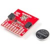
 SparkFun Real Time Clock Module - RV-8803 QwiicSPARKFUN
¥4,998税込¥5,498
1個
33日以内出荷
DescriptionThe SparkFun RV-8803 Real Time Clock Module is a Qwiic-enabled breakout board for the RV-8803 RTC. The RV-8803 boasts some impressive features including a temperature compensated crystal providing extremely precise time-keeping, low power consumption, and time stamp event input along with a user-programmable timing offset value. The RV-8803 also has an improved I2C interface compared to the RV-1805 RTC that removes the need to sequence commands/writes to the device. Best of all, the temperature compensation comes factory calibrated. Utilizing our handy Qwiic system so no soldering is required to connect it to the rest of your system. However, we still have broken out 0.1"-spaced pins in case you prefer to use a breadboard.Adding a real-time clock to your project is the perfect way to get more accurate data; timing or otherwise. Using the Qwiic connector makes for a fast, solid way to incorporate this into your project. The RTC module has counters for hundredths of seconds, seconds, minutes, hours, date, month, year and weekday with a number of alarm and interrupt settings available as well. Plus the large operating temperature range(-40 to +105℃)and temperature compensated crystal makes for a good addition for field applications or harsh environments.The SparkFun Qwiic Connect System is an ecosystem of I2C sensors, actuators, shields and cables that make prototyping faster and less prone to error. All Qwiic-enabled boards use a common 1mm pitch, 4-pin JST connector. This reduces the amount of required PCB space, and polarized connections mean you can't hook it up wrong.Get Started with the SparkFun RV-8803 Real Time Clock Module GuideFeaturesFactory Calibrated Temperature CompensationHigh Time Accuracy±1.5 ppm 0 to +50℃±3.0 ppm -40 to +85℃±7.0 ppm +85 to +105℃1.5V to 5.5V Operating Voltage Range240nA @ 3.3v Low-Power ConsumptionI2C Address:0x32Periodic Countdown Timer Interrupt functionPeriodic Time Update Interrupt function(seconds, minutes)Alarm Interrupts for weekday or date, hour and minute settingsExternal Event Input with Interrupt and Time Stamp functionProgrammable Clock Output pin for peripheral devices.Operating temperature range:-40 to +105℃2x Qwiic Connectors
アズワン品番67-0420-10
 LOAD CELL AMP HX711SPARKFUN
¥2,898税込¥3,188
1個
予約販売
DescriptionThe SparkFun Load Cell Amplifier is a small breakout board for the HX711 IC that allows you to easily read load cells to measure weight. By connecting the amplifier to your microcontroller you will be able to read the changes in the resistance of the load cell, and with some calibration you'll be able to get very accurate weight measurements. This can be handy for creating your own industrial scale, process control or simple presence detection.This version of the SparkFun Load Cell Amplifier features a few changes that you specifically asked for! We have separated the analog and digital supply, as well as added a 3.3uH inductor and a 0.1uF filter capacitor for digital supply. Need even more? Checkout the SparkFun Qwiic Scale. It has all the features of the HX711 but with additional library support, a true I2C interface, and no soldering required!The HX711 uses a two-wire interface(Clock and Data)for communication. Any microcontroller's GPIO pins should work, and numerous libraries have been written, making it easy to read data from the HX711. Check the hookup guide below for more information.Load cells use a four-wire Wheatstone bridge configuration to connect to the HX711. These are commonly colored RED, BLK, WHT, GRN and YLW. Each color corresponds to the conventional color coding of load cells:Red(Excitation+ or VCC)Black(Excitation- or GND)White(Amplifier-, Signal- or Output-)Green(A+, S+ or O+)Yellow(Shield)The YLW pin acts as an optional input that is not hooked up to the strain gauge but is utilized to ground and shield against outside EMI(electromagnetic interference). Please keep in mind that some load cells might have slight variations in color coding.Note:Special thanks to Bodge for supplying the Library for the HX711!Get Started with the HX711 Load Cell Amplifier GuideFeaturesOperation Voltage:2.7V--5VOperation Current:< 1.5mASelectable 10SPS or 80SPS output data rateSimultaneous 50 and 60Hz supply rejection
アズワン品番67-0362-17
 I/O Expander - MCP23008SPARKFUN
¥599税込¥659
1個
33日以内出荷
DescriptionAdd another eight pins to your microcontroller using a MCP23008 port expander. The MCP23008 uses two I2C pins which can be shared with other I2C devices, and in exchange gives you eight general purpose pins. You can set each of eight pins to be input, output, or input with a pullup. There's even the ability to get an interrupt via an external pin when any of the inputs change so you don't have to keep polling the chip.Use this chip from 2.7-5.5V(good for any 3.3V or 5V setup), and you can sink/source up to 20mA from any of the I/O pins so this will work for LEDs and such. Team it up with a high-power MOSFET if you need more juice. DIP package means it will plug into any breadboard or perfboard.You can set the I2C address by tying the ADDR0-2 pins to power or ground, for up to eight unique addresses. That means eight chips can share a single I2C bus - that's 64 I/O pins!Features8-bit remote bidirectional I/O portHigh-speed I2C interface(MCP23008)Hardware address pinsConfigurable interrupt output pinConfigurable interrupt sourcePolarity Inversion register for input port data polarity config.External reset inputLow standby current:1 μA(max.)・ Operating voltage:1.8V to 5.5V @ -40℃ to +85℃ I2C @ 100 kHz SPI @ 5 MHz2.7V to 5.5V @ -40℃ to +85℃ I2C @ 400 kHz SPI @ 10 MHz4.5V to 5.5V @ -40℃ to +125℃ I2C @ 1.7 kHz SPI @ 10 MHz
アズワン品番67-0421-32
 Himax CMOS Imaging Camera - HM01B0SPARKFUN
¥3,298税込¥3,628
1個
33日以内出荷
DescriptionThe HM01B0 from Himax Imaging is an ultra low power CMOS Monochrome Image Sensor that enables the integration of an "Always On" camera for computer vision applications such as gestures, intelligent ambient light and proximity sensing, tracking and object identification. The sensor allows the sensor to consume very low power of <2mW at QVGA 30FPS. This low power consumption and vision applications camera comes with a ribbon cable that mates to the camera connector populated on the following products:MicroMod Machine Learning Carrier BoardArtemis Development KitEdge Development Board - Apollo3 BlueThe HM01B0 contains 320×320 pixel resolution and supports a 320×240 window mode which can be readout at a maximum frame rate of 60FPS, and a 2×2 monochrome binning mode with a maximum frame rate of 120FPS. The video data is transferred over a configurable 1bit, 4bit or 8bit interface with support for frame and line synchronization. The sensor integrates black level calibration circuit, automatic exposure and gain control loop, self-oscillator and motion detection circuit with interrupt output to reduce host computation and commands to the sensor to optimize the system power consumption.FeaturesImage SensorUltra Low Power Image Sensor(ULPIS)designed for Always On vision devices and applicationsHigh sensitivity 3.6μ BrightSenseTM pixel technology320×320 active pixel resolution with support for QVGA window, vertical flip and horizontal mirror readoutProgrammable black level calibration target, frame size, frame rate, exposure, analog gain(up to 8x)and digital gain(up to 4x)Automatic exposure and gain control loop with support for 50 / 60Hz flicker avoidanceFlexible 1bit, 4bit and 8bit video data interface with video frame and line syncMotion Detection circuit with programmable ROI and detection threshold with digital output to serve as an interruptOn-chip self oscillatorI2C 2-wire serial interface for register accessHigh CRA for low profile module designSensor ParametersActive Pixel Array 320×320Pixel Size 3.6 μm×3.6 μmFull Image Area 1152 μm×1152 μmDiagonal(Optical Format)1.63 mm(1/11″)Scan Mode:ProgressiveShutter Type:Electronic Rolling ShutterFrame Rate MAX 51 fps @ 320×320, 60 fps @ 320×240(QVGA)CRA(maximum)30℃Sensor SpecificationsSupply Voltage:Analog - 2.8 V, Digital - 1.5V(Internal LDO:1.5V - 2.8V), I/O - 1.5 - 2.8VInput Reference Clock:3 - 50 MHzSerial Interface(I2C):2-wire, 400 KHz max.Video Data Interface:1b, 4b, 8b with frame / line SYNCOutput Clock Rate MAX:50 MHz for 1bit, 12.5 MHz for 4bit, 6.25 MHz for 8bitEst. Power Consumption(include IO with 5pF load):QVGA 60FPS(Typical)<4 mWQVGA 30FPS(Typical)<2 mW
アズワン品番67-0427-08
 Binho Nova Multi-Protocol USB Host AdapterSPARKFUN
¥77,980税込¥85,778
1個
33日以内出荷
DescriptionThe Binho Nova Multi-Protocol USB Host Adapter allows one to interface their computer directly to hardware circuits. This device is powered by the USB connection to the host PC and is also able to provide downstream power to test circuits.The Binho Nova Multi-Protocol USB Host Adapter features 5 signal pins, one×3v3 pin, one×VUSB pin, and three×GND pins on its 10pin wire harness. The wire harness terminates with a female 1.27mm 2x5 IDC connector. In IO Mode, the five signal pins can be used for varying functions such as Digital Input, Digital Output, PWM Output, Digital Interrupt(on rising edge, falling edge, or change), Analog Input, or Analog Output.Additionally, the host adapter is able to utilize these pins to communicate on several digital buses:I2C, SPI, UART,(Dallas)1-Wire, and(Atmel)Single-Wire Interface. While in these modes of operation, remaining available pins can be assigned to other related or unrelated purposes such as gpio, interrupts, chip selects, PWM signals, or analog input or outputs.The Binho Nova Multi-Protocol USB Host Adapter is ideal for manual testing during firmware development and debugging as well as a perfect way to automate hardware testing and validation. A common use-case of this product in production environments is for EEPROM/Flash Memory programming along with functional testing activities.FeaturesSupport for SPI @ 12MHz max clockSupport for I2C @ 3.4MHz max clockSupport for UART @ 1000000 max baudSupport for Dallas 1-WireSupport for Atmel Single-Wire InterfaceProvides 3v3 and VUSB power rails1×DAC Output, 5×ADC InputsGPIO / Interrupt / PWM SupportProgrammable RGB Status LEDField-Upgradeable Device FirmwareCross-platform Support for Windows,Mac, LinuxRobust, low-profile AluminumEnclosureUSB Type-C Connector
アズワン品番67-0423-03
 SparkFun Qwiic Button - Green LEDSPARKFUN
¥1,498税込¥1,648
1個
33日以内出荷
DescriptionButtons are an easy and tactile way to interface with your project, but why would you want to deal with debouncing, polling, and wiring up pull-up resistors? The Qwiic Button with built-in green LED simplifies all of those nasty worries away into an easy to use I2C device! Utilizing our Qwiic Connect System, using the button is as simple as connecting cable and loading up some pre-written code!If you need multiple buttons for your project, fear not! Each button has configurable I2C address, so you can daisy-chain multiple buttons over Qwiic and still address each one individually. We've got an example in our Arduino library that provides super-easy way to configure your Qwiic Button to whatever I2C address you desire. You can download the library through the Arduino library manager by searching 'SparkFun Qwiic Button' or you can get the GitHub repo as .zip file and install the library from there.In addition to handling blinking and debouncing, the Qwiic Button has configurable interrupts that can be configured to activate upon button press or click. We've also taken the liberty of implementing FIFO queue onboard the Qwiic Button where it keeps an internal record of when the button was pressed. This means that code on your microcontroller need not waste valuable processing time checking the status of the button but instead can run small function whenever the button is pressed or clicked! For more information on interrupts check out our guide here!The SparkFun Qwiic Connect System is an ecosystem of I2C sensors, actuators, shields and cables that make prototyping faster and less prone to error. All Qwiic-enabled boards use common 1mm pitch, 4-pin JST connector. This reduces the amount of required PCB space, and polarized connections mean you can't hook it up wrong.Get Started with the SparkFun Qwiic Button GuideFeatures12mm Green LED Button rated for 50mABuilt in LED can be configured for your desired level of blinkiness!Each button has configurable I2C addressConfigurable interrupts check out our guide here!FIFO queueDon't like the color green? Check out the SparkFun Qwiic Button Breakout and add another colored button!Red LED Tactile ButtonBlue LED Tactile ButtonGreen LED Tactile ButtonWhite LED Tactile Button
アズワン品番67-0420-14