「contrex」の検索結果

Description。Jump-start your IoT development with the Omega2+ Starter Kit. This kit includes everything you need to create eight different circuits that will teach you how to control LEDs, read inputs, control and read external sensors and displays, learn Python, and more. Step-by-step instructions for building each circuit with the included parts can be found in the online Starter Kit Guide under the "Documents" tab.。Each Starter Kit includes an Onion Omega2+ IoT Computer, an Expansion Dock and a variety of electronics components that belong in the collection of every student of Internet of Things. This collection includes resistors, LEDs, jumper wires, switches, a 7-segment display and an LCD screen, to name a few. All kit components are nicely packed up in a handy plastic carrying case.。The Onion Omega parts we carry are separated into three different categories:Mainboard, Dock and Expansion Board. With the parts in this kit you will be able to plug the Omega2+ into the Expansion Dock and add any Expansion Board! For a kit that includes all of the parts in the Starter Kit plus the Expansion Boards, check out the Omega2+ Maker Kit.。Examples。Blinking an LED --- Learn the basics of programming the Omega by turning an LED on and off.。Blinking Multiple LEDs --- Learn some more programming concepts by controlling multiple LEDs at once.。Fading an LED --- Create a cool LED fading effect using the Pulse Width Modulation(PWM)technique.。Reading a Switch --- Use a physical switch to control an LED through the Omega.。Using a Shift Register --- Use a shift register chip to control eight LEDs using only a few GPIOs.。Controlling a 7-Segment Display --- Add a 7-segment display to the previous circuit to display numbers.。Reading a 1-Wire Temperature Sensor --- Use a 1-wire temperature sensor to read the ambient temperature.。Controlling an LCD Screen --- Use the I2C protocol to control an LCD screen attached to the previous circuit.
アズワン品番67-0424-15
1個
¥33,980
税込¥37,378
33日以内出荷

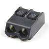
Description。Poke Home Connectors have been featured on a number of our boards over the last few years by providing a simple screw-terminal-type connector for easy wire connection purposes. Similar to screw terminals, Poke Home Connectors grasp a wire entered into the receiving area of the pin-out by pressing down on the small plastic strip at the end of the housing. Doing so raises the internal clamp and, upon release of the button secures the wire in place without any soldering required.。Poke Home Connectors work better in environments with a lot of vibrations(i.e. automotive applications)or when a wire is expanding or contracting due to temperature cycling. Additionally, the tension in the connector is automatically adjusted to the wire gauge(assuming it is within the accepted wire thickness)as opposed to variances in tension when a user tightens the screw terminal.
アズワン品番67-0425-83
1個
¥109
税込¥120
33日以内出荷

。Description。The SparkFun Inventor's Kit(SIK)for Arduino Uno is a great way to get started with programming and hardware interaction with the Arduino programming language. The SIK includes everything you need to complete five overarching projects consisting of 16 interconnected circuits that teach everything from blinking an LED to reading sensors. The culminating project is your very own autonomous robot! No previous programming or electronics experience is required to use this kit.。The online guide contains step-by-step instructions with circuit diagrams and hookup tables for building each project and circuit with the included parts. Full example code is provided, new concepts and components are explained at point of use, and troubleshooting tips offer assistance if something goes wrong.。The kit does not require any soldering and is recommended for beginners ages 10 and up who are looking for an Arduino starter kit. For SIK version 4.1 we took an entirely different approach to teaching embedded electronics. In previous versions of the SIK, each circuit focused on introducing a new piece of technology. With SIK v4.1, components are introduced in the context of the circuit you are building, and each circuit builds upon the last, leading up to a project that incorporates all of the components and concepts introduced throughout the guide. With new parts and a completely new strategy, even if you've used the SIK before, you're in for a brand-new experience!。This version of the SIK replaces the SparkFun RedBoard Qwiic with the Arduino Uno(SMD version)and comes without the SIK guidebook and carrying case. With these components being swapped and removed, we were able to reduce the overall size and weight of the kit, making shipping cheaper and easier for anyone ordering internationally.。Note:As stated above, this SIK does NOT include a carrying case or print guidebook.。Get Started With the SparkFun Inventor's Kit v4.1 Experiment Guide。Examples。Project 1:Light。Circuit 1A:Blinking an LED。Circuit 1B:Potentiometer。Circuit 1C:Photoresistor。Circuit 1D:RGB Night-Light。Project 2:Sound。Circuit 2A:Buzzer。Circuit 2B:Digital Trumpet。Circuit 2C:"Simon Says" Game。Project 3:Motion。Circuit 3A:Servo Motors。Circuit 3B:Distance Sensor。Circuit 3C:Motion Alarm。Project 4:Display。Circuit 4A:LCD "Hello, World!"。Circuit 4B:Temperature Sensor。Circuit 4C:"DIY Who Am I?" Game。Project 5:Robot。Circuit 5A:Motor Basics。Circuit 5B:Remote-Controlled Robot。Circuit 5C:Autonomous Robot
アズワン品番67-0424-34
1個
¥24,980
税込¥27,478
33日以内出荷

Description。It's tiny, it's handy, and it can give your normal USB-equipped device a micro-B connector! With the USB to Micro-B Adapter you can make a flash drive connect to your tablet, connect a keyboard to your phone in order to text with ease, attach a Bluetooth(R)dongle to your RPi Zero, and more! Since this adapter is super small, it is very easy to transport anywhere you might need it --- making it extremely convenient to have in a pinch.。Installation of the USB to Micro-B Adapter is easy; simply slide it into a USB A connector, and you will instantly make that device micro-B capable!
アズワン品番67-0421-07
1個
¥469
税込¥516
33日以内出荷

。Description。The HM01B0 from Himax Imaging is an ultra low power CMOS Monochrome Image Sensor that enables the integration of an "Always On" camera for computer vision applications such as gestures, intelligent ambient light and proximity sensing, tracking and object identification. The sensor allows the sensor to consume very low power of <2mW at QVGA 30FPS. This low power consumption and vision applications camera comes with a ribbon cable that mates to the camera connector populated on the following products:MicroMod Machine Learning Carrier Board。Artemis Development Kit。Edge Development Board - Apollo3 Blue。The HM01B0 contains 320×320 pixel resolution and supports a 320×240 window mode which can be readout at a maximum frame rate of 60FPS, and a 2×2 monochrome binning mode with a maximum frame rate of 120FPS. The video data is transferred over a configurable 1bit, 4bit or 8bit interface with support for frame and line synchronization. The sensor integrates black level calibration circuit, automatic exposure and gain control loop, self-oscillator and motion detection circuit with interrupt output to reduce host computation and commands to the sensor to optimize the system power consumption.。Features。Image Sensor。Ultra Low Power Image Sensor(ULPIS)designed for Always On vision devices and applications。High sensitivity 3.6μ BrightSenseTM pixel technology。320×320 active pixel resolution with support for QVGA window, vertical flip and horizontal mirror readout。Programmable black level calibration target, frame size, frame rate, exposure, analog gain(up to 8x)and digital gain(up to 4x)。Automatic exposure and gain control loop with support for 50 / 60Hz flicker avoidance。Flexible 1bit, 4bit and 8bit video data interface with video frame and line sync。Motion Detection circuit with programmable ROI and detection threshold with digital output to serve as an interrupt。On-chip self oscillator。I2C 2-wire serial interface for register access。High CRA for low profile module design。Sensor Parameters。Active Pixel Array 320×320。Pixel Size 3.6 μm×3.6 μm。Full Image Area 1152 μm×1152 μm。Diagonal(Optical Format)1.63 mm(1/11″)。Scan Mode:Progressive。Shutter Type:Electronic Rolling Shutter。Frame Rate MAX 51 fps @ 320×320, 60 fps @ 320×240(QVGA)。CRA(maximum)30℃。Sensor Specifications。Supply Voltage:Analog - 2.8 V, Digital - 1.5V(Internal LDO:1.5V - 2.8V), I/O - 1.5 - 2.8V。Input Reference Clock:3 - 50 MHz。Serial Interface(I2C):2-wire, 400 KHz max.。Video Data Interface:1b, 4b, 8b with frame / line SYNC。Output Clock Rate MAX:50 MHz for 1bit, 12.5 MHz for 4bit, 6.25 MHz for 8bit。Est. Power Consumption(include IO with 5pF load):QVGA 60FPS(Typical)<4 mW。QVGA 30FPS(Typical)<2 mW
アズワン品番67-0427-08
1個
¥2,998
税込¥3,298
33日以内出荷

Description。The SparkFun I2S Audio Breakout board uses the MAX98357A digital to analog converter(DAC), which converts I2S(not be confused with I2C)audio to an analog signal to drive speakers. The I2S Audio Breakout converts the digital audio signals using the I2S standard to an analog signal and amplifies the signal using a class D amplifier which can deliver up to 3.2W of power into a 4Ω load. The board can be configured to output only the left channel audio, right channel, or both.。The SparkFun I2S Audio Breakout board is fairly simple, requiring only a few pin connections to get it up and working. By default the board is configured in "mono" operation, meaning the left and right signals are combined together to drive a single speaker. If you want a separate speaker for the left and right audio channels you'll need to cut the mono jumper. In addition to being able to select the audio channel output, the gain can also be configured in a few ways. The gain of the amplifier can be configured from as low as +3dB to as high as +15dB. While the channel selection can be configured on board, the gain however is controlled externally using the gain pin. By default, the board is configured for +9dB, but can be easily changed!。Get Started with the SparkFun I2S Audio Breakout Guide。Features。Supply Voltage Range:2.5V - 5.5V.。Output Power:3.2W into 4Ω at 5V.。Output Channel Selection:Left, Right, or Left/2 + Right/2(Default).。Sample Rate:8kHz - 96kHz.。Sample Resolution:16/32 bit.。Quiescent Current:2.4mA.。Filterless Class D Outputs。No MCLK Required。Click and Pop Reduction。Short-Circuit and Thermal Protection.
アズワン品番67-0422-64
1個
¥1,398
税込¥1,538
33日以内出荷

Description。The CD40106BE consists of six Schmitt-trigger circuits. Each circuit functions as an inverter with Schmitt-trigger action on the input. The trigger switches at different points for positive- and negative-going signals. The difference between the positive-going voltage(VP)and the negative-going voltage(VN)is defined as hysteresis voltage(VH).。Features。Schmitt trigger action with no external components。Hysteresis voltage typ. at 0.9V at VDD = 5V, 2.3V at VDD = 10V, and 3.5V at VDD = 15V。Noise immunity greater than 50%。No limit on input rise and fall times。Standardised, symmetrical output characteristics。100% tested for quiescent current at 20sV。Maximum input current of 1μA at 18 V over full package temperature range; 100nA at 18V and 25℃。Low VDD to VSS current during slow input ramp
アズワン品番67-0420-89
1個
¥679
税込¥747
33日以内出荷

。Description。The SparkFun Wireless Joystick Kit provides an easy way to control your next XBee project. Before the wireless joystick, radio-controlled projects used hobby RC transmitters, the same ones used for RC cars, boats and planes. The problem with these transmitters is that many aren't customizable, and the ones that are tend to be too expensive for many of us. The Wireless Joystick Kit offers a custom wireless solution for those who want to control their project their own way.。Equipped with the increasingly popular SAMD21 onboard, all you need is to assemble the SparkFun Wireless Joystick into the configuration you want and add your own XBee and lithium ion battery into the provided sockets. The Wireless Joystick Kit can be assembled into a configuration that utilizes dual joysticks for better RC steering robots(like tanks)or a single joystick configuration with four 12mm momentary pushbuttons(a setup similar to what older game consoles used). We have provided a full Hookup Guide that gives assembly instructions, as well as a tank-steering motor controller tutorial to help get you started!。Please be aware that the SparkFun Wireless Joystick Kit is。NOT supported on Windows 7/8。due to a lack of support drivers for those specific OS's.。Note:This kit will need to be assembled before use, so a beginner's knowledge of soldering will be required. Additionally, in an effort to keep shipping rates down and make this kit available to people throughout the world without delay, there is no XBee or lithium ion battery included.。Get Started with the Wireless Joystick Kit Guide
アズワン品番67-0424-08
1個
¥10,980
税込¥12,078
33日以内出荷

Description。The SparkFun TFT LCD Breakout is a versatile, colorful, and easy way to experiment with graphics or create a user interface for your project. With a 4-wire SPI interface and microSD card holder, you can use this breakout to easily add visual display/interface capabilities to a project as well as providing all the storage you might need for multimedia files.。To get started with this breakout, you will need an Arduino compatible microcontroller of your choice - we recommend something with extra RAM like the SparkFun Thing Plus. The breakout can be powered with either 5V or 3.3V. The microSD card holder is connected to the same SPI bus as the display which keeps the required pin count low and exists to relieve the burden from your microcontroller's poor memory due to having to store hundreds of images of cats, or really whatever you want to keep there. We have also gone ahead and tricked out the SparkFun HyperDisplay library with a driver made especially for this breakout!。Out of the box, the SparkFun TFT LCD Breakout will come with a large backing PCB that makes it easy to securely mount the display in a project. If you need a more flexible solution you can remove the display module, snap off half the backing board, and then re-insert the display module. When this is done you'll be left with the bare minimum frame around the display to more seamLessly integrate with your project.。Get Started With the SparkFun TFT LCD Breakout Guide。Features。128×160 RGB pixels。Up to 18 bit configurable color depth。2x PWM controllabele LED backlight。microSD Card Slot。V-Score for Minimal Footprint Setup
アズワン品番67-0424-97
1個
¥8,798
税込¥9,678
33日以内出荷

Description。The LIDAR-Lite v4 LED sensor is the next step in the LIDAR-Lite line. A small, lightweight, low-power optical ranging sensor. It's the first to incorporate ANT profile wireless networking technology into an optical sensor. Its built-in nRF52840 processor means that developers can create custom applications, or be operated as a stand-alone device right out of the box by using the preloaded stock application.。Like the LIDAR-Lite v3 and LIDAR-Lite v3HP sensors; it can also be directly connected to an external micro-controller running a custom user application. As such, it provides a highly adaptable option for OEM and maker applications in robotics, Internet of Things, and unmanned vehicles ― or any application where an ultrasonic sensor might otherwise be used. It's perfect as the basic building block for applications where wireless capabilities, small size, light weight, low power consumption and high performance are important factors in a short-range, 10-meter, optical distance measuring sensor.。The LIDAR-Lite v4 requires an external 5VDC power source and soldering is required. This Time-of-Flight ranging module uses a LED and optics for ranging. It does not use a laser; therefore, it is inherently eye-safe under normal usage.。Features。Resolution:1 cm。Measurement repeatability:As measured indoors to a 90% reflective target。1 cm is equivalent to 1 standard deviation。Using "high accuracy" mode, with averaging:+/- 1 cm to 2 meters。+/- 2 cm to 4 meters。+/- 5 cm to 10 meters。Range:5 cm to 10 meters(as measured from back of unit)。Update rate:I2C = >200 Hz typical。ANT(R)= up to 200 Hz to a 90% target indoors at 2m in normal operating mode。Interface:I2C or ANT; user configurable for SPI using the Nordic SDK。Power(operating voltage):4.75 - 5.25 VDC。Current consumption:2mA idle, 85mA during acquisition。Operating temperature:-20 to 60° C。LED wavelength:940 nm。Beam divergence:4.77°。Optical aperture:14.9 mm。Unit size(HxWxD):2.1"×0.8"×0.9"(52.2×21.2×24.0 mm)。Weight:14.6 g(0.5 oz)
アズワン品番67-0427-09
1個
¥18,980
税込¥20,878
33日以内出荷

Description。The Teensy is an amazing and compact development platform in breadboard friendly form factor, but what if you could incorporate it into the Arduino architecture? The Teensy Arduino Shield Adapter allows you to attach your Teensy and utilize your favorite Arduino shields without the requirement of breadboard or any complicated wiring. Needless to say, the Teensy Arduino Shield Adapter is useful tool for upgrading all of your existing Arduino projects to more powerful controller!。As we stated before, the Teensy Arduino Shield Adapter provides basic Arduino compatibility with your run-of-the-mill shield but there are few other fun features that we've added on, as well. These features include Real Time Clock(RTC)battery, JST battery connector, 4-12V barrel jack connector, an ICSP header, and more. Because this board is simply an adapter, there is no special programming required to start working with the adapter. You will, however, need to program the Teensy for any Arduino shield you'd like to work with.。While the adapter design can fit the Teensy LC footprint, it has been designed to fully utilize the features of the Teensy 3.1. Not all of the features available on the adapter are compatible with the LC so please be sure to check the Hookup Guide in the。Documents。section below to ensure functionality for your project. Please keep in mind that this adapter may be incompatible with some 5V Arduino shields. Please check our hookup guide for more information.。Note:The Teensy Arduino Shield Adapter comes as kit and will need to be soldered together.。Note:Due to the requirements of shipping the batteries in this kit, orders may take longer to process and therefore do not qualify for same-day shipping. Additionally, these batteries can not be shipped via Ground or Economy methods to Alaska or Hawaii. Sorry for any inconvenience this may cause.。Features。Arduino R3 Interface。Real Time Clock Battery。JST Battery Connector。Barrel Jack。I2C Jumpers。ICSP Header。DAC Pin Header
アズワン品番67-0424-36
1個
¥3,298
税込¥3,628
33日以内出荷

Description。The SparkFun MicroMod Environmental Function Board adds additional sensing options to the MicroMod Processor Boards. This Function Board includes three sensors to monitor air quality(SGP40), humidity temperature(SHTC3), and CO2 concentrations(STC31)in your indoor environment. To make it even easier to use, all communication is over the MicroMod's I2C bus!。The SGP40 measures the quality of the air in your room or house. The SGP40 uses a metal oxide(MOx)sensor with a temperature controlled micro hotplate and provides a humidity-compensated volatile organic compound(VOC)based indoor air quality signal. Both the sensing element and VOC Algorithm feature an unmatched robustness against contaminating gases present in real world applications enabling a unique long term stability as well as low drift and device to device variation.。The SHTC3 is a highly accurate digital humidity and temperature sensor. The SHTC3 uses a capacitive humidity sensor with a relative humidity measurement range of 0 to 100% RH and bandgap temperature sensor with a temperature measurement range of -40℃ to 125℃. The SHTC3 builds on the success of their SHTC1 sensor with higher accuracy(±2% RH, ±0.2℃)than its predecessor, enabling greater flexibility.。The STC31 measures CO2 concentrations based on thermal conductivity and has two CO2 measurement ranges:0 to 25 vol%; and 0 to 100 vol%. The measurement repeatability is 0.2 vol%, with a stability of 0.025 vol% / ℃. The measurement accuracy depends on the measurement range:0.5 vol% + 3% measured value; 1 vol% + 3% measured value. Using measurements from the SHTC3, the STC31 is able to provide humidity-compensated measurements together with improved temperature compensation. The STC31 can compensate for atmospheric pressure too - which is handy if, like us, you're up in the mountains!。The outstanding performance of these three sensors is based on Sensirion's patented CMOSens(R)technology, which combines the sensor element, signal processing, and digital calibration on a small CMOS chip. The well-proven CMOS technology is perfectly suited for high-quality mass production and is the ideal choice for demanding and cost-sensitive OEM applications.。Utilizing our handy M.2 MicroMod connector, no soldering is required to connect it to your system. Simply match up the key on your processor and function board's beveled edge connector to their respective key on the M.2 connector, then secure them to the main board with screws. The MicroMod Environmental Function Board can then be read via the I2C port. The board is equipped with the AP2112 3.3V voltage regulator, I2C pull-up resistors, power LED, jumper to disable the LED, and jumpers for alternative STC31 addresses.。Note:A MicroMod Processor and Main Board are not included with this MicroMod Environmental Function Board. These boards will need to be purchased separately.。MicroMod is a modular interface ecosystem that connects a microcontroller "processor board" to various "carrier board" peripherals. Utilizing the M.2 standard, the MicroMod standard is designed to easily swap out processors and function boards on the fly. Pair a specialized carrier board for the project you need with your choice of compatible processor!。Get Started with the MicroMod Environmental Function Board。Features。Input voltage range。2.5V to 6.0V。Typ.。5V。via Main Board's USB connector。Typ.。~3.7V to 4.2V。via Main Board's LiPo battery Connector。I/O voltage。3.3V。AP2112 3.3V voltage regulator(rated 600mA)。Power LED。I2C pull-up resistors。Sensirion SGP40 Air Quality Sensor。Uses I2C interface。Address:0x59(default)。Operating voltage range。1.7V to 3.6V(Typ.。3.3V。)。Operating temperature range。-20℃ to +55℃。Typical current consumption。2.6mA。during continuous operation(at 3.3V)。34μA。when idle(heater off)。Output signal。Digital raw value(SRAW):0 - 65535 ticks。Digital processed value(VOC Index):0 - 500 VOC index points。Switch-on behavior。Time until reliably detecting VOC events:<60s。Time until specifications are met:<1h。Recommended sampling interval。VOC Index:1s。SRAW:0.5s - 10s(Typ. 1s)。Sensirion SHTC3 Humidity and Temperature Sensor。Uses I2C interface。Address:0x70(default, non-configurable)。Operating voltage range。1.62V - 3.6V(Typ.。3.3V。)。Operating temperature range。-40℃ to +125 ℃。Relative Humidity。Measurement range:0% to 100%。Typical accuracy:±2 %RH。Resolution:0.01 %RH。Temperature。Measurement range:-40℃ to +125 ℃。Typical accuracy:±0.2 ℃。Resolution:0.01 ℃。Typical current consumption(varies based on mode)。4.9μA to 430μA(Normal Mode)。0.5μA to 270μA(Low Power Mode)。Allows the STC31 to compensate for humidity and temperature。Sensirion STC31 CO2 Sensor。Uses I2C interface。Addresses:0x29(default)。, 0x2A, 0x2B, 0x2C。Operating voltage range。2.7V to 5.5V(Typ.。3.3V。)。Operating temperature range。-20 ℃ to +85 ℃。Calibrated for CO2 in N2 and CO2 in air。Measurement ranges。0 to 25 vol% in N2。0 to 100 vol% in air。Accuracy。0.5 vol% + 3% measured value in N2。1 vol% + 3% measured value in air。Concentration and temperature resolution:16-bit。Repeatability:0.2 vol%。Temperature stability:0.025 vol% / ℃。Start-up time:14 ms。Thermal conductivity sensor provides calibrated gas concentration and temperature output。Jumpers。PWR LED。I2C pull-up resistors。STC31 address selection。Note:The I2C addresses that are reserved for each sensor is 0x59(SGP40), 0x70(SHTC3), 0x29(STC31). A multiplexer/Mux is required to communicate to multiple SHTC3 sensors on a single bus. The SHTC3 uses the same address as the Qwiic Mux(0x70). For advanced users that are using multiple SHTC3's with the Qwiic Mux, you will need to adjust the Qwiic Mux's default address.
アズワン品番67-0427-60
1個
¥38,980
税込¥42,878
33日以内出荷