


「di2」の検索結果
特価
本日1月11日(日)は、モノタロウブランドの全商品がキャンペーンコード入力で通常価格より
10%
引き!
キャンペーンコード
000026260116
キャンペーンコードのご利用方法
※特価からの更なる割引はございません
関連キーワード


Description。With the SparkFun Qwiic Connect System expanding every day, we want to make sure it becomes as accessible as possible but we understand there are other systems that can compliment it out there. The Qwiic to Grove Adapter Cable allows interoperability between the SparkFun Qwiic Connect System and the I2C based Grove boards from Seeed Studio. Now you can plug Seeed Studio boards you may have onto the Qwiic bus or you can use this cable to introduce Qwiic sensors, inputs, and outputs into your Grove system.。Note:The Grove system has a variety of different signal systems that use the same connector. This cable。only。works with the I2C variety.。The SparkFun Qwiic connect system is an ecosystem of I2C sensors, actuators, shields and cables that make prototyping faster and less prone to error. All Qwiic-enabled boards use a common 1mm pitch, 4-pin JST connector. This reduces the amount of required PCB space, and polarized connections mean you can't hook it up wrong.。。Features。Length:100mm
アズワン品番67-0425-61
1個
¥659
税込¥725
33日以内出荷

Description。The SparkFun NEO-M9N GPS Breakout is a high quality GPS board with equally impressive configuration options including SMA. The NEO-M9N module is a 92-channel u-blox M9 engine GNSS receiver, meaning it can receive signals from the GPS, GLONASS, Galileo, and BeiDou constellations with ~1.5 meter accuracy. This breakout supports concurrent reception of four GNSS. This maximizes position accuracy in challenging conditions increasing, precision and decreases lock time; and thanks to the onboard rechargeable battery, you'll have backup power enabling the GPS to get a hot lock within seconds! Additionally, this u-blox receiver supports I2C(u-blox calls this Display Data Channel)which makes it perfect for the Qwiic compatibility so we don't have to use up our precious UART ports. Utilizing our handy Qwiic system, no soldering is required to connect it to the rest of your system. However, we still have broken out 0.1"-spaced pins in case you prefer to use a breadboard.。The NEO-M9N module detects jamming and spoofing events and can report them to the host, so that the system can react to such events. A SAW(Surface Acoustic Wave)filter combined with an LNA(Low Noise Amplifier)in the RF path is integrated into the NEO-M9N module which allows normal operation even under strong RF interferences.。U-blox based GPS products are configurable using the popular, but dense, windows program called u-center. Plenty of different functions can be configured on the NEO-M9N:baud rates, update rates, geofencing, spoofing detection, external interrupts, SBAS/D-GPS, etc. All of this can be done within the SparkFun Arduino Library!。The SparkFun NEO-M9N GPS Breakout is also equipped with an on-board rechargeable battery that provides power to the RTC on the NEO-M9N. This reduces the time-to-first fix from a cold start(~24s)to a hot start(~2s). The battery will maintain RTC and GNSS orbit data without being connected to power for plenty of time.。This product requires an antenna:Be sure to check out the related products/hookup accessories and pick a suitable SMA antenna for your project.。The SparkFun Qwiic Connect System is an ecosystem of I2C sensors, actuators, shields and cables that make prototyping faster and less prone to error. All Qwiic-enabled boards use a common 1mm pitch, 4-pin JST connector. This reduces the amount of required PCB space, and polarized connections mean you can't hook it up wrong.。The NEO-M9N GPS Breakout can also be automatically detected, scanned, configured, and logged using the OpenLog Artemis datalogger system. No programming, soldering, or setup required!。Get Started With the SparkFun NEO-M9N GPS Guide。Features。Integrated SMA connector for use with antenna of your choice。92-Channel GNSS Receiver。1.5m Horizontal Accuracy。25Hz Max Update Rate(four concurrent GNSS)。Time-To-First-Fix:Cold:24s。Hot:2s。Max Altitude:80,000m。Max G:≦4。Max Velocity:500m/s。Velocity Accuracy:0.05m/s。Heading Accuracy:0.3 degrees。Time Pulse Accuracy:30ns。3.3V VCC and I/O。Current Consumption:~31mA Tracking GPS+GLONASS。Software Configurable。Geofencing。Odometer。Spoofing Detection。External Interrupt。Pin Control。Low Power Mode。Many others!。Supports NMEA, UBX, and RTCM protocols over UART or I2C interfaces
アズワン品番67-0423-87
1個
¥19,980
税込¥21,978
33日以内出荷

Description。The SparkFun I2S Audio Breakout board uses the MAX98357A digital to analog converter(DAC), which converts I2S(not be confused with I2C)audio to an analog signal to drive speakers. The I2S Audio Breakout converts the digital audio signals using the I2S standard to an analog signal and amplifies the signal using a class D amplifier which can deliver up to 3.2W of power into a 4Ω load. The board can be configured to output only the left channel audio, right channel, or both.。The SparkFun I2S Audio Breakout board is fairly simple, requiring only a few pin connections to get it up and working. By default the board is configured in "mono" operation, meaning the left and right signals are combined together to drive a single speaker. If you want a separate speaker for the left and right audio channels you'll need to cut the mono jumper. In addition to being able to select the audio channel output, the gain can also be configured in a few ways. The gain of the amplifier can be configured from as low as +3dB to as high as +15dB. While the channel selection can be configured on board, the gain however is controlled externally using the gain pin. By default, the board is configured for +9dB, but can be easily changed!。Get Started with the SparkFun I2S Audio Breakout Guide。Features。Supply Voltage Range:2.5V - 5.5V.。Output Power:3.2W into 4Ω at 5V.。Output Channel Selection:Left, Right, or Left/2 + Right/2(Default).。Sample Rate:8kHz - 96kHz.。Sample Resolution:16/32 bit.。Quiescent Current:2.4mA.。Filterless Class D Outputs。No MCLK Required。Click and Pop Reduction。Short-Circuit and Thermal Protection.
アズワン品番67-0422-64
1個
¥1,698
税込¥1,868
33日以内出荷

Description。The DHT20 is a low cost humidity and temperature sensor with a I2C digital output protocol. It can be applied to HVAC, dehumidifier, automatic control, data loggers, weather stations, and many other projects. The sensor is calibrated and doesn't require extra components so you can get right to measuring relative humidity and temperature.。Features。Supply Voltage:2.2-5.5V。Communication:Standard I2C Protocol。Humidity from 0-100% RH。Typical accuracy:RH:±3%, T:±0.5℃。-40 - 80 degrees C temperature range
アズワン品番67-0427-56
1個
¥2,498
税込¥2,748
欠品中

Description。The SparkFun Qwiic SHIM for Raspberry Pi is a small, easily removable breakout that easily adds a Qwiic connector to your Raspberry Pi. The SHIM design allows you to plug directly to the Pi's I2C bus with no soldering required and the thin
アズワン品番67-0422-90
1個
¥469
税込¥516
欠品中

Description。The SparkFun QwiicBus EndPoint is the fastest and easiest way to extend the range of your I2C communication bus. The breakout uses NXP's PCA9615 IC, which converts the two default I2C signals into four differential signals, two for SCL and
アズワン品番67-0421-65
1個
¥3,598
税込¥3,958
欠品中

Description。The SparkFun Qwiic MicroPressure Sensor is a miniature breakout equipped with Honeywell's 25psi piezoresistive silicon pressure sensor. This MicroPressure Sensor offers a calibrated and compensated pressure sensing range of 60mbar to 2.5bar, easy to read 24 bit digital I2C output, and can be calibrated and compensated over a specific temperature range for sensor offset, sensitivity, temperature effects, and non-linearity using an on-board Application Specific Integrated Circuit(ASIC). With its ultra-low power consumption and Qwiic ports, you've got yourself a power packed little sensor!。Each Qwiic MicroPressure Sensor has a calibrated pressure sensing range from 1-25psi and a power consumption rate as low as 0.01mW typ. average power, 1Hz measurement frequency for ultimate portability. Used in multiple medical(blood pressure monitoring, negative pressure wound therapy), industrial(air braking systems, gas and water meters), and consumer uses(coffee machines, humidifiers, air beds, washing machines, dishwashers), the SparkFun Qwiic MicroPressure Sensor is a great addition to the SparkFun Qwiic ecosystem!。The SparkFun Qwiic Connect System is an ecosystem of I2C sensors, actuators, shields and cables that make prototyping faster and less prone to error. All Qwiic-enabled boards use a common 1mm pitch, 4-pin JST connector. This reduces the amount of required PCB space, and polarized connections mean you can't hook it up wrong.。Get Started with the SparkFun Qwiic MicroPressure Hookup Guide。Features。Pressure Type:Absolute。Operating Pressure:25psi(172.37kPa)。I2C Address:0x18。Accuracy:±0.25%。Voltage - Supply:1.8V-3.6V。Port Size:Male - 0.1"(2.5mm)Tube。Port Style:Barbless。Maximum Pressure:60psi(413.69kPa)。Compatible with a variety of liquid media。2x Qwiic Connectors
アズワン品番67-0427-25
1個
¥22,980
税込¥25,278
33日以内出荷

Description。Here is the Zio Qwiic 1.5inch 128×128 pixels OLED display module. It can display a maximum of 16 lines of text content, and display pictures and animation on its 1.5-inch display. On the backside, there are two Qwiic connectors. With the Qwiic connect system no soldering is required to connect it to the rest of your system.。Fit for use in small embedded systems, and also suitable for any projects that require displays of any kind, this screen is a must-have for Makers to include in even as one of their wearable DIY projects.。The SparkFun Qwiic Connect System is an ecosystem of I2C sensors, actuators, shields and cables that make prototyping faster and less prone to error. All Qwiic-enabled boards use a common 1mm pitch, 4-pin JST connector. This reduces the amount of required PCB space, and polarized connections mean you can't hook it up wrong.。。Features。Resolution:128×128 pixels。Display IC:SSD1327。I2C address:0x78, 0x7A(Default:0x78)。Display Color:White
アズワン品番67-0424-98
1個
¥10,980
税込¥12,078
欠品中

Description。The TFMini-S Micro LiDAR Module is a ToF(Time of Flight)LiDAR sensor capable of measuring the distance to an object as close as 10 centimeters(+/- 6cm up to 6m)and as far as 12 meters(+/-1% starting at 6m)! As with all LiDAR sensors, your effective detection distance will vary depending on lighting conditions and the reflectivity of your target object, but what makes this sensor special is its size. Measuring only 42x15x16mm, the TFMini-S allows you to integrate LiDAR into applications traditionally reserved for smaller sensors.。TFMini-S is a single-point ranging LiDAR based on TFmini upgrade. The blind zone is shortened to 10cm, the outdoor performance and accuracy of different reflectivity are improved, it can achieve stable, accuracy, sensitive and high frequency range detection.。Important:This product does not use laser light for ranging. Instead it contains an LED and optics. Many such systems are being marketed under the name "LiDAR," although it may be more appropriate to think of this device as a "Time-of-Flight Infrared Rangefinder". It differs significantly from traditional IR rangefinders in that it uses ToF to determine range and not triangulation ― as is performed by the Sharp GP-series devices.。Features。Operating Range:0.1m~12m@90%Reflectivity。0.1~7m@10% Reflectivity。0.1m~12m@90%Reflectivity(70Klux)。0.1~7m@10% Reflectivity(70Klux)。Accuracy:±6cm@(0.1-6m)。±1%@(6m-12m)。Distance Resolution:1cm。Frame Rate:100Hz。Ambient light immunity:70Klux。Operating Temperature:0℃~60℃。Light source:VCSEL。Central wavelength:850nm。Photobiological safety:Class1(EN60825)。FOV:2°2。Supply voltage:5V±0.1V。Average current:≦140mA。Power consumption:≦0.7W。Peak current:200mA。Communication level:LVTTL(3.3V)。Communication interface:UART / I2C。Dimension:42mmx15mmx16mm(LxWxH)。Housing:PC/ABS。Storage temperature:-20℃~75℃。Weight:5g±0.3g。Cable length:10cm
アズワン品番67-0427-33
1個
¥21,980
税込¥24,178
欠品中

Description。The SparkFun Alphanumeric Display Arduino library makes printing strings to the display as easy as calling the print()function. With this library, you'll be able to send I2C commands to the VK16K33 LED driver chip to light up segments(including the decimal point or colon)and even scroll your string across the display. You can download the library through the Arduino library manager by searching 'SparkFun Alphanumeric Display' or you can get the GitHub repo as a .zip file and install the library from there.。The SparkFun Qwiic Connect System is an ecosystem of I2C sensors, actuators, shields and cables that make prototyping faster and less prone to error. All Qwiic-enabled boards use a common 1mm pitch, 4-pin JST connector. This reduces the amount of required PCB space, and polarized connections mean you can't hook it up wrong.。Get Started with the Qwiic Alphanumeric Display Hookup Guide。Features。Operating Voltage:3.3V。Integrated RC oscillator。Maximum display segment numbers:128 patterns。13×3 matrix key scan circuit。16-step dimming circuit。I2C Addresses:0x70(0x71, 0x72, 0x73)。2x Qwiic connectors。2x Wall Mounting Points
アズワン品番67-0421-62
1個
¥2,298
税込¥2,528
33日以内出荷

Description。The SparkFun Alphanumeric Display Arduino library makes printing strings to the display as easy as calling the print()function. With this library, you'll be able to send I2C commands to the VK16K33 LED driver chip to light up segments(including the decimal point or colon)and even scroll your string across the display. You can download the library through the Arduino library manager by searching 'SparkFun Alphanumeric Display' or you can get the GitHub repo as a .zip file and install the library from there.。The SparkFun Qwiic Connect System is an ecosystem of I2C sensors, actuators, shields and cables that make prototyping faster and less prone to error. All Qwiic-enabled boards use a common 1mm pitch, 4-pin JST connector. This reduces the amount of required PCB space, and polarized connections mean you can't hook it up wrong.。Get Started with the Qwiic Alphanumeric Display Hookup Guide。Features。Operating Voltage:3.3V。Integrated RC oscillator。Maximum display segment numbers:128 patterns。13×3 matrix key scan circuit。16-step dimming circuit。I2C Addresses:0x70(0x71, 0x72, 0x73)。2x Qwiic connectors。2x Wall Mounting Points
アズワン品番67-0421-64
1個
¥2,398
税込¥2,638
33日以内出荷

Description。The SparkFun Alphanumeric Display Arduino library makes printing strings to the display as easy as calling the print()function. With this library, you'll be able to send I2C commands to the VK16K33 LED driver chip to light up segments(including the decimal point or colon)and even scroll your string across the display. You can download the library through the Arduino library manager by searching 'SparkFun Alphanumeric Display' or you can get the GitHub repo as a .zip file and install the library from there.。The SparkFun Qwiic Connect System is an ecosystem of I2C sensors, actuators, shields and cables that make prototyping faster and less prone to error. All Qwiic-enabled boards use a common 1mm pitch, 4-pin JST connector. This reduces the amount of required PCB space, and polarized connections mean you can't hook it up wrong.。Get Started with the Qwiic Alphanumeric Display Hookup Guide。Features。Operating Voltage:3.3V。Integrated RC oscillator。Maximum display segment numbers:128 patterns。13×3 matrix key scan circuit。16-step dimming circuit。I2C Addresses:0x70(0x71, 0x72, 0x73)。2x Qwiic connectors。2x Wall Mounting Points
アズワン品番67-0421-63
1個
¥2,298
税込¥2,528
33日以内出荷

Description。This is an evaluation board for the Silicon Laboratories Si4703 FM tuner chip. Beyond enabling you to tune in to FM radio stations, the Si4703 is also capable of detecting and processing both Radio Data Service(RDS)and Radio Broadcast Data Service(RBDS)information. The Si4703 even does a very good job of filtering and carrier detection. It also enables data such as the station ID and song name to be displayed to the user.。Using this board, you will be able to pick up multiple stations just as well as with a standard FM radio. The board breaks out all major pins and makes it easy to incorporate this great chip into your next radio project. The power bus, the 3.3V and GND pins are broken out For communication. The breakout provides access to SDIO and SCLK for I2C communication while RST can be used for easy resetting. The SEN pin enables the user to change the mode of functionality of the IC. The last two pins broken out are GPIO1 and GPIO2 which can be used as general input/output pins, but also can be used for things like the RDS ready, seeking or tuning functions.。Keep in mind, by plugging headphones into the 3.5mm audio jack, you effectively use the cable in your headphones as an antenna! Therefore, this board does not require an external antenna if using headphones or a 3.5mm audio cable longer than 3 feet.
アズワン品番67-0429-34
1個
¥6,698
税込¥7,368
33日以内出荷

Description。The SparkFun Alphanumeric Display Arduino library makes printing strings to the display as easy as calling the print()function. With this library, you'll be able to send I2C commands to the VK16K33 LED driver chip to light up segments(including the decimal point or colon)and even scroll your string across the display. You can download the library through the Arduino library manager by searching 'SparkFun Alphanumeric Display' or you can get the GitHub repo as a .zip file and install the library from there.。The SparkFun Qwiic Connect System is an ecosystem of I2C sensors, actuators, shields and cables that make prototyping faster and less prone to error. All Qwiic-enabled boards use a common 1mm pitch, 4-pin JST connector. This reduces the amount of required PCB space, and polarized connections mean you can't hook it up wrong.。Get Started with the Qwiic Alphanumeric Display Hookup Guide。Features。Operating Voltage:3.3V。Integrated RC oscillator。Maximum display segment numbers:128 patterns。13×3 matrix key scan circuit。16-step dimming circuit。I2C Addresses:0x70(0x71, 0x72, 0x73)。2x Qwiic connectors。2x Wall Mounting Points
アズワン品番67-0421-61
1個
¥2,298
税込¥2,528
33日以内出荷

Description。The SparkFun Qwiic HAT for Raspberry Pi is the quickest and easiest way to enter into SparkFun's Qwiic ecosystem while still using that Raspberry Pi that you've come to know and love. The Qwiic HAT connects the I2C bus(GND, 3.3V, SDA and SCL)on your Raspberry Pi to an array of Qwiic connectors on the HAT. Since the Qwiic system allows for daisy chaining boards with different addresses, you can stack as many sensors as you'd like to create a tower of sensing power!。The Qwiic Pi HAT has four Qwiic connect ports, all on the same I2C bus. In addition, many of the useful GPIO pins on the Raspberry Pi are broken out. This HAT is compatible with any Raspberry Pi that utilizes the standard 2x20 GPIO header. It has been designed to sit to the side of the Pi, allowing it to work conveniently with a Pi Tin enclosure to connect boards to the Qwiic ports.。Note:。There is a small silk error that has reversed the SDA and SCL. This is simply a cosmetic mix-up and will not impact any function with this board.。The SparkFun Qwiic Connect System is an ecosystem of I2C sensors, actuators, shields and cables that make prototyping faster and less prone to error. All Qwiic-enabled boards use a common 1mm pitch, 4-pin JST connector. This reduces the amount of required PCB space, and polarized connections mean you can't hook it up wrong.。Get Started with the SparkFun Qwiic Pi HAT Guide。Features。4x Qwiic Connection Ports。Select GPIO Pins Broken Out。Pi Tin Compatibility
アズワン品番67-0422-50
1個
¥1,798
税込¥1,978
33日以内出荷

。Description。The Binho Nova Multi-Protocol USB Host Adapter allows one to interface their computer directly to hardware circuits. This device is powered by the USB connection to the host PC and is also able to provide downstream power to test circuits.。The Binho Nova Multi-Protocol USB Host Adapter features 5 signal pins, one×3v3 pin, one×VUSB pin, and three×GND pins on its 10pin wire harness. The wire harness terminates with a female 1.27mm 2x5 IDC connector. In IO Mode, the five signal pins can be used for varying functions such as Digital Input, Digital Output, PWM Output, Digital Interrupt(on rising edge, falling edge, or change), Analog Input, or Analog Output.。Additionally, the host adapter is able to utilize these pins to communicate on several digital buses:I2C, SPI, UART,(Dallas)1-Wire, and(Atmel)Single-Wire Interface. While in these modes of operation, remaining available pins can be assigned to other related or unrelated purposes such as gpio, interrupts, chip selects, PWM signals, or analog input or outputs.。The Binho Nova Multi-Protocol USB Host Adapter is ideal for manual testing during firmware development and debugging as well as a perfect way to automate hardware testing and validation. A common use-case of this product in production environments is for EEPROM/Flash Memory programming along with functional testing activities.。Features。Support for SPI @ 12MHz max clock。Support for I2C @ 3.4MHz max clock。Support for UART @ 1000000 max baud。Support for Dallas 1-Wire。Support for Atmel Single-Wire Interface。Provides 3v3 and VUSB power rails。1×DAC Output, 5×ADC Inputs。GPIO / Interrupt / PWM Support。Programmable RGB Status LED。Field-Upgradeable Device Firmware。Cross-platform Support for Windows,Mac, Linux。Robust, low-profile AluminumEnclosure。USB Type-C Connector
アズワン品番67-0423-03
1個
¥77,980
税込¥85,778
33日以内出荷

Description。The micro:bit v2 Educator's Lab Pack includes 10 micro:bit v2 boards and everything you need to get you started with the new learning platform. The Lab Pack has everything you need, including micro:bits, cables, battery packs and a few parts to experiment with. This package provides an easy way to introduce your students to the micro:bit without any difficulty or parts hunting.。SparkFun packages everything educators need to get started with the micro:bit in a variety of classroom settings and learning environments. The hardware boards, cables and extra parts come pre-packaged. Examples and curriculum materials are available from SparkFun and micro:bit, as well as from other educators involved in this growing maker education movement.。Lab Packs are your classroom entry point. By combining our kits, popular boards and other educational tools with support materials(to be updated), SparkFun brings all the power of the open source community to the classroom. We've also updated the battery pack to be closer to what is in other micro:bit kits. It now requires 2xAAA batteries.。The micro:bit is a pocket-sized computer that lets you get creative with digital technology. Between the micro:bit and our shield-like bit boards you can do almost anything while coding, customizing and controlling your micro:bit from almost anywhere! You can use your micro:bit for all sorts of unique creations, from robots to musical instruments and more. At half the size of a credit card, this versatile board has vast potential!。。Features。Micro:bit 2.0:64 MHz Arm Cortex-M4 with FPU。512KB Flash。128KB RAM。5x5 Red LED Array。Two Programmable Buttons, one touch sensitive logo。MEMS microphone and LED indicator。Onboard Light, Compass, Accelerometer, Temp Sensors and Speaker。2.4 Ghz Micro:bit Radio/BLE 5.0 Smart Antenna。25-pin Edge Connector。4 dedicated GPIO, PWM, i2c, SPI, and ext. power。Three Digital/Analog Input/Output Rings。Two Power Rings --- 3V and GND。Dedcated I2C bus for peripherals。MicroUSB Connector(5V)。JST-PH Battery Connector(。Not。JST-XH)(3V)。Power/reset Button with Status LED。200 mA available for accessories。Program with C++, MakeCode, Python, Scratch
アズワン品番67-0424-92
1個
¥99,980
税込¥109,978
33日以内出荷

Description。The SparkFun Qwiic LED Stick features ten addressable APA102 LEDs, making it easy to add full color LED control using I2C. Write to individual LEDs to display a count in binary, or write to the whole strip for cool lighting effects. You can even add more LEDs to the end if you need to. We've written an Arduino library and Python package that take care of the I2C and communication to the LEDs so all you have to do is decide what color each LED should be.。The LED Stick has a default I2C address of 0x23 but can be changed with a simple command, allowing you to control up to 100 LEDs(10 Qwiic LED Sticks)on a single bus! The address can also be changed to 0x22 by closing the solder jumper on the back of the board.。This board is one of our many Qwiic compatible boards! Simply plug and go. No soldering, no figuring out which is SDA or SCL, and no voltage regulation or translation required!。Warning:Using a lot of LEDs can draw a lot of current. Make sure to consider the power limits of your setup. If you expect your LED chain to draw more than 600mA of current, connect your external supply directly to VLED. Closing the jumper from VLED to VCC will add a 4.7uF decoupling capacitor.。The SparkFun Qwiic Connect System is an ecosystem of I2C sensors, actuators, shields and cables that make prototyping faster and less prone to error. All Qwiic-enabled boards use a common 1mm pitch, 4-pin JST connector. This reduces the amount of required PCB space, and polarized connections mean you can't hook it up wrong.。Get Started with the Qwiic LED Stick Guide。Features。10x APA102C addressable LEDs driven by an ATTiny85。Default I2C Address:0x23(Adjustable to 0x22 via Jumper)。2x Qwiic Connectors
アズワン品番67-0421-83
1個
¥2,998
税込¥3,298
33日以内出荷

Description。Leveraging the ultra powerful Artemis Module, the SparkFun MicroMod Artemis Processor is the brain board of your dreams. With a Cortex-M4F with BLE 5.0 running up to 96MHz and with as low power as 6uA per MHz(less than 5mW), the M.2 MicroMod connector allows you to plug in a MicroMod Carrier Board with any number of peripherals. Let's have a look at what this processor board has to offer! If you need Machine Learning capabilities, Bluetooth, I2C functionality to connect to all our amazing Qwiic boards, and more the Artemis Processor is the perfect choice for your MicroMod Carrier Board.。At the heart of SparkFun's Artemis Module is Ambiq Micro's Apollo3 processor, whose ultra-efficient ARM Cortex-M4F processor is spec'd to run TensorFlow Lite using only 6uA/MHz. We've routed two I2C buses, eight GPIO, dedicated digital, analog, and PWM pins, multiple SPI as well as QuadSPI, and Bluetooth to boot. You really can't go wrong with this processor. Grab one today, pick up a compatible carrier board, and get hacking!。MicroMod is a modular interface ecosystem that connects a microcontroller "processor board" to various "carrier board" peripherals. Utilizing the M.2 standard, the MicroMod standard is designed to easily swap out processors on the fly. Pair a specialized carrier board for the project you need with your choice of compatible processor!。Get Started with the MicroMod Artemis Processor Guide。Features。Artemis General Features。1M Flash / 384k RAM。48MHz / 96MHz turbo available。6uA/MHz(operates less than 5mW at full operation)。48 GPIO - all interrupt capable。31 PWM channels。Built in BLE radio and antenna。10 ADC channels with 14-bit precision with up to 2.67 million samples per second effective continuous, multi-slot sampling rate。2 channel differential ADC。2 UARTs。6 I2C buses。6 SPI buses。2/4/8-bit SPI bus。PDM interface。I2S Interface。Secure 'Smart Card' interface。FCC/IC/CE Certified(ID Number 2ASW8-ART3MIS)。Specific Peripherals made available on MicroMod Artemis:1x USB dedicated for programming and debug。1x UART with flow control。2x I2C。1x SPI。1x Quad-SPI。8x Fast GPIO。2x Digital Pins。2x Analog Pins。2x PWM。1x Differential ADC pair。Status LED。VIN Level ADC。Additional peripherals are available but are shared on dedicated MicroMod pins.
アズワン品番67-0423-05
1個
¥5,598
税込¥6,158
33日以内出荷

Description。The SparkFun moto:bit is a fully loaded "carrier" board for the micro:bit that, when combined with the micro:bit, provides you with a fully functional robotics platform. The moto:bit offers a simple, beginner-friendly robotics controller capable of operating a basic robotics chassis. Onboard each moto:bit are multiple I/O pins, as well as a vertical Qwiic connector, capable of hooking up servos, sensors and other circuits. At the flip of the switch you can get your micro:bit moving!。The moto:bit connects to the micro:bit via an updated SMD, edge connector at the top of the board, making setup easy. This creates a handy way to swap out micro:bits for programming, while still providing reliable connections to all of the different pins on the micro:bit. We have also included a basic barrel jack on the moto:bit that is capable of providing power to anything you connect to the carrier board.。The micro:bit is a pocket-sized computer that lets you get creative with digital technology. Between the micro:bit and our shield-like bit boards you can do almost anything while coding, customizing and controlling your micro:bit from almost anywhere! You can use your micro:bit for all sorts of unique creations, from robots to musical instruments and more. At half the size of a credit card, this versatile board has vast potential!。Note:The SparkFun moto:bit does。NOT。include a micro:bit board. The micro:bit will need to be purchased separately.。Get started with the moto:bit Guide。Features。More reliable Edge connector for easy use with the micro:bit。Full H-Bridge for control of two motors。Control servo motors。Vertical Qwiic Connector。I2C port for extending functionality。Power and battery management onboard for the micro:bit
アズワン品番67-0422-89
1個
¥8,498
税込¥9,348
33日以内出荷

Description。We are quite familiar with seven-segment displays. We see them on our alarm clocks, ovens, and microwaves. By adding more segments to each digit you can display more than just numbers! Introducing the brand new SparkFun Qwiic Alphanumeric Display. These white fourteen-segment digits allow you display all sorts of numbers, characters, and symbols. With Qwiic, simply plug it in and go. No soldering, no figuring out which is SDA or SCL, and no voltage regulation or translation required!。The SparkFun Alphanumeric Display Arduino library makes printing strings to the display as easy as calling the print()function. With this library, you'll be able to send I2C commands to the VK16K33 LED driver chip to light up segments(including the decimal point or colon)and even scroll your string across the display. You can download the library through the Arduino library manager by searching 'SparkFun Alphanumeric Display' or you can get the GitHub repo as a .zip file and install the library from there.。The VK16K33 also supports I2C address configuration. Simply close a combination of the address jumpers on the back and you can communicate with up to four displays on the same bus. Our slim board design also features detachable stand off holes, vertical Qwiic connectors, and internal mounting holes.。The SparkFun Qwiic Connect System is an ecosystem of I2C sensors, actuators, shields and cables that make prototyping faster and less prone to error. All Qwiic-enabled boards use a common 1mm pitch, 4-pin JST connector. This reduces the amount of required PCB space, and polarized connections mean you can't hook it up wrong.。Get Started with the Qwiic Alphanumeric Display Hookup Guide。Features。White display。Operating Voltage:3.3V。Integrated RC oscillator。Maximum display segment numbers:128 patterns。13×3 matrix key scan circuit。16-step dimming circuit。I2C Addresses:0x70(0x71, 0x72, 0x73)。2x Qwiic connectors。2x Wall Mounting Points
アズワン品番67-0421-87
1個
¥2,298
税込¥2,528
33日以内出荷

Description。The SCD30 from Sensirion is a high quality Nondispersive Infrared(NDIR)based CO2 sensor capable of detecting 400 to 10000ppm with an accuracy of ±(30ppm+3%). In order to improve accuracy the SCD30 has temperature and humidity sensing built-in, as well as commands to set the current altitude. For additional accuracy the SCD30 also accepts ambient pressure readings!。We've written an Arduino library to make reading the CO2, humidity, and temperature very easy. It can be downloaded through the Arduino Library manager:search for 'SparkFun SCD30' or it can be found in the。Documents。tab above.。The SCD30 Humidity and Temperature Sensor can also be automatically detected, scanned, configured, and logged using the OpenLog Artemis datalogger system. No programming, soldering, or setup required!。Note:The SCD30 has an automatic self-calibration routine. Sensirion recommends 7 days of continuous readings with at least 1 hour a day of 'fresh air' for self-calibration to complete.。Features。Power supply voltage:3.3V - 5.5V。NDIR CO2 sensor technology。Integrated temperature and humidity sensor。Best performance-to-price ratio。Dual-channel detection for superior stability。Small form factor:35 mm×23 mm×7 mm。Measurement range:400 ppm - 10.000 ppm。Accuracy:±(30 ppm + 3%)。Current consumption:19 mA @ 1 meas. per 2 s.。Energy consumption:120 mJ @ 1 measurement。Fully calibrated and linearized。Digital interface UART or I2C
アズワン品番67-0430-35
1個
¥21,980
税込¥24,178
33日以内出荷
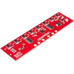
Description。The SparkFun Line Follower Array is a long board consisting of eight IR sensors that have been configured to read as digital bits! We have designed the SparkFun Line Follower Arrays to follow a dark line of about 3/4 inch width or smaller(spray paint or electrical tape)on a light background. Each array features visible LEDs that point upward when the board is attached(properly)so you can see what the robot sees, brightness control right on the board, and an I2C interface for reading and power control. Here at SparkFun, the RedBot Shadow Chassis was used as a test platform but really this was designed as an add-on for almost any bot.。The line follower functions by taking an 8-bit reading of reflectance for use with following lines or reading dark/light patterns and can see from about 1/4 to 3/4 inches away. The IR brightness control and indicator can be adjusted with the on-board potentiometer and is capable of showing you the strength of the IR LEDs. Illumination can be turned on and off with software to conserve power, or left on all the time for faster readings. The SparkFun Line Follower Array requires 5V of power with a supply current range of 25-185mA with strobing disabled and 16-160mA with it enabled. Additionally we have added six mounting holes to the line follower with the two inner holes designed to fit our Shadow Chassis while the other four are general purpose.。Note:As you know our Sun emits quite a bit of infrared light, making the SparkFun Line Follower Array much less effective in direct sunlight. Plan your projects accordingly!。Features。8 sensor eyes(QRE1113, like in our line sensor breakout)。I2C interface。Adjust IR brightness on the fly with a knob。Switch IR on and off with software。Switch visual indicators on and off with software。Invert dark/light sight with software。Based on the SX1509 I/O expander
アズワン品番67-0426-55
1個
¥11,980
税込¥13,178
欠品中

。Description。Add another eight pins to your microcontroller using a MCP23008 port expander. The MCP23008 uses two I2C pins which can be shared with other I2C devices, and in exchange gives you eight general purpose pins. You can set each of eight pins to be input, output, or input with a pullup. There's even the ability to get an interrupt via an external pin when any of the inputs change so you don't have to keep polling the chip.。Use this chip from 2.7-5.5V(good for any 3.3V or 5V setup), and you can sink/source up to 20mA from any of the I/O pins so this will work for LEDs and such. Team it up with a high-power MOSFET if you need more juice. DIP package means it will plug into any breadboard or perfboard.。You can set the I2C address by tying the ADDR0-2 pins to power or ground, for up to eight unique addresses. That means eight chips can share a single I2C bus - that's 64 I/O pins!。Features。8-bit remote bidirectional I/O port。High-speed I2C interface(MCP23008)。Hardware address pins。Configurable interrupt output pin。Configurable interrupt source。Polarity Inversion register for input port data polarity config.。External reset input。Low standby current:1 μA(max.)・ Operating voltage:。1.8V to 5.5V @ -40℃ to +85℃ I2C @ 100 kHz SPI @ 5 MHz。2.7V to 5.5V @ -40℃ to +85℃ I2C @ 400 kHz SPI @ 10 MHz。4.5V to 5.5V @ -40℃ to +125℃ I2C @ 1.7 kHz SPI @ 10 MHz
アズワン品番67-0421-32
1個
¥599
税込¥659
33日以内出荷

Description。The SparkFun ZOE-M8Q GPS Breakout is a high accuracy, miniaturized, GPS board that is perfect for applications that don't possess a lot of space. The on-board ZOE-M8Q is a 72-channel GNSS receiver, meaning it can receive signals from the GPS, GLONASS, BeiDou, and Galileo constellations. This increases precision and decreases lock time and thanks to the onboard rechargable battery you'll have backup power enabling the GPS to get a hot lock within seconds! Additionally, this u-blox receiver supports I2C(u-blox calls this Display Data Channel)which made it perfect for the Qwiic compatibility so we don't have to use up our precious UART ports. Utilizing our handy Qwiic system, no soldering is required to connect it to the rest of your system. However, we still have broken out 0.1"-spaced pins in case you prefer to use a breadboard.。U-blox based GPS products are configurable using the popular, but dense, windows program called u-center. Plenty of different functions can be configured on the ZOE-M8Q:baud rates, update rates, geofencing, spoofing detection, external interrupts, SBAS/D-GPS, etc. All of this can be done within the SparkFun Arduino Library. We've also made sure to configure the UART pin grouping on the breakout to an industry standard to insure that it easily connects to a Serial Basic.。The SparkFun ZOE-M8Q GPS Breakout is also equipped with an on-board rechargeable battery that provides power to the RTC on the ZOE-M8Q. This reduces the time-to-first fix from a cold start(~30s)to a hot start(~1s). The battery will maintain RTC and GNSS orbit data without being connected to power for up to five hours. Since the ZOE-M8Q is a tiny GPS receiver and to minimize its footprint, we've added a U.FL connector to allow the use of both large standard ceramic antennas as well as very small chip scale antennas.。Note:The I2C address of the ZOE-M8Q is 0x42 and is software configurable. A multiplexer/Mux is required to communicate to multiple ZOE-M8Q sensors on a single bus. If you need to use more than one ZOE-M8Q sensor consider using the Qwiic Mux Breakout.。The SparkFun Qwiic Connect System is an ecosystem of I2C sensors, actuators, shields and cables that make prototyping faster and less prone to error. All Qwiic-enabled boards use a common 1mm pitch, 4-pin JST connector. This reduces the amount of required PCB space, and polarized connections mean you can't hook it up wrong.。The ZOE-M8Q GPS Breakout can also be automatically detected, scanned, configured, and logged using the OpenLog Artemis datalogger system. No programming, soldering, or setup required!。Get Started With the SparkFun ZOE-M8Q Hookup Guide。Features。72-Channel GNSS Receiver。2.5m Horizontal Accuracy。18Hz Max Update Rate。Time-To-First-Fix:Cold:26s。Hot:1s。Max Altitude:50,000m。Max G:≦4。Max Velocity:500m/s。Velocity Accuracy:0.05m/s。Heading Accuracy:0.3 degrees。Time Pulse Accuracy:30ns。3.3V VCC and I/O。Current Consumption:~29mA Tracking GPS+GLONASS。Software Configurable。Geofencing。Odometer。Spoofing Detection。External Interrupt。Pin Control。Low Power Mode。Many others!。Supports NMEA, UBX, and RTCM protocols over UART or I2C interfaces
アズワン品番67-0423-76
1個
¥13,980
税込¥15,378
33日以内出荷

Description。This 7" Raspberry Pi Touchscreen LCD provides you with the ability to create a standalone device that can be utilized as a custom tablet or an all-in-one interactive interface for a future project using your Raspberry Pi 3. Each LCD features a full color 800×480 capacitive touch display that connects to the Pi via an included adapter board which handles all of your power and signal conversion needs. An updated version of Raspbian OS on the A+, B+ and Pi2B is required for the display to work(the display does not work with the current version of Raspbian available on the Model A or B).。What makes this LCD great is the fact that it only requires two connections to be hooked up to the Pi; power from the Pi's GPIO port and a ribbon cable that connects to the DSI port present on all Raspberry Pi's. Touchscreen drivers with support for 10-finger touch and an on-screen keyboard allow you to use your Raspberry Pi without an external keyboard or mouse.。With this Raspberry Pi LCD you can create your own 'Internet of Things'(IoT)devices including a visual display by simply connecting your Pi, developing a easy Python script to interact with the display, and you'll be ready to create your own home automation devices with touch screen capability.。Note:The latest version of Raspbian OS is required for this Raspberry Pi LCD to operate correctly.。Features。7" Touchscreen Display.。Screen Dimensions:194mm×110mm×20mm(including standoffs)。Viewable screen size:155mm×86mm。70 degree viewing angle。Screen Resolution 800×480 pixels @ 60fps。24-bit color。10 finger capacitive touch.。Connects to the Raspberry Pi board using a ribbon cable connected to the DSI port.。Adapter board is used to power the display and convert the parallel signals from the display to the serial(DSI)port on the Raspberry Pi.
アズワン品番67-0457-43
1セット
¥21,980
税込¥24,178
33日以内出荷

Description。Are you low on I/O? No problem! The SX1509 Breakout is 16-channel GPIO expander with an I2C interface that means with just two wires, your microcontroller can interface with 16 fully configurable digital input/output pins. But the SX1509 can do so much more than just simple digital pin control. It can produce PWM signals, so you can dim LEDs. It can be set to blink or even breathe pins at varying rates. This breakout is similar to multiplexer or "mux," in that it allows you to get more IO from less pins. And, with built-in keypad engine, it can interface with up to 64 buttons set up in an 8x8 matrix.。Two headers at the top and bottom of the breakout board function as the input and control headers to the board. This is where you can supply power to the SX1509, and where your I2C signals SDA and SCL will terminate. GPIO and power buses are broken out in every-which direction, and configurable jumpers cover most of the rest of the board.。Since the I/O banks can operate between 1.2V and 3.6V(5.5V tolerant)independent of both the core and each other, this device can also work as level-shifter. The SX1509 breakout makes it easy to prototype so you can add more I/O onto your Arduino or I/O limited controller. We've even spun up an Arduino Library to get you started!。Features。Enable Direct Level Shifting Between I/O Banks and Host Controller。5.5V Tolerant I/Os, Up to 15mA Output Sink on All I/Os。Integrated LED Driver with Intensity Control。On-Chip Keypad Scanning Engine Supports Up to 8x8 Matrix(64 Keys)。16 Channels of True Bi-directional Style I/O。400kHz I2C Compatible Slave Interface
アズワン品番67-0419-88
1個
¥2,098
税込¥2,308
33日以内出荷

。Description。The SparkFun RV-8803 Real Time Clock Module is a Qwiic-enabled breakout board for the RV-8803 RTC. The RV-8803 boasts some impressive features including a temperature compensated crystal providing extremely precise time-keeping, low power consumption, and time stamp event input along with a user-programmable timing offset value. The RV-8803 also has an improved I2C interface compared to the RV-1805 RTC that removes the need to sequence commands/writes to the device. Best of all, the temperature compensation comes factory calibrated. Utilizing our handy Qwiic system so no soldering is required to connect it to the rest of your system. However, we still have broken out 0.1"-spaced pins in case you prefer to use a breadboard.。Adding a real-time clock to your project is the perfect way to get more accurate data; timing or otherwise. Using the Qwiic connector makes for a fast, solid way to incorporate this into your project. The RTC module has counters for hundredths of seconds, seconds, minutes, hours, date, month, year and weekday with a number of alarm and interrupt settings available as well. Plus the large operating temperature range(-40 to +105℃)and temperature compensated crystal makes for a good addition for field applications or harsh environments.。The SparkFun Qwiic Connect System is an ecosystem of I2C sensors, actuators, shields and cables that make prototyping faster and less prone to error. All Qwiic-enabled boards use a common 1mm pitch, 4-pin JST connector. This reduces the amount of required PCB space, and polarized connections mean you can't hook it up wrong.。Get Started with the SparkFun RV-8803 Real Time Clock Module Guide。Features。Factory Calibrated Temperature Compensation。High Time Accuracy。±1.5 ppm 0 to +50℃。±3.0 ppm -40 to +85℃。±7.0 ppm +85 to +105℃。1.5V to 5.5V Operating Voltage Range。240nA @ 3.3v Low-Power Consumption。I2C Address:0x32。Periodic Countdown Timer Interrupt function。Periodic Time Update Interrupt function(seconds, minutes)。Alarm Interrupts for weekday or date, hour and minute settings。External Event Input with Interrupt and Time Stamp function。Programmable Clock Output pin for peripheral devices.。Operating temperature range:-40 to +105℃。2x Qwiic Connectors
アズワン品番67-0420-10
1個
¥4,998
税込¥5,498
33日以内出荷

。Description。The SparkFun Qwiic Motor Driver takes all the great features of the Serial Controlled Motor Driver(SCMD)and miniaturizes them, adding Qwiic ports for plug and play functionality. Boasting the same 4245 PSOC and 2-channel motor ports as the SCMD, the SparkFun Qwiic Motor Driver is designed to communicate over I2C to make setting up your next robotic project as fast and easy as possible! Utilizing our handy Qwiic system and screw terminals for motor and power hook-up, no soldering is required to connect it to the rest of your system.。With 1.2A steady state drive per channel(1.5A peak)and 127 levels of DC drive strength, this little Qwiic board is perfect for your small DC motor driver needs. Since the Qwiic Motor Driver is a 3.3V logic device, you'll need to use a logic level converter to interface to 5V.。The I2C address of the Qwiic Motor Driver is 0x5D and is jumper selectable to 0x58, 0x59, 0x5A, 0x5B, ... 0x63.。The SparkFun Qwiic Connect System is an ecosystem of I2C sensors, actuators, shields and cables that make prototyping faster and less prone to error. All Qwiic-enabled boards use a common 1mm pitch, 4-pin JST connector. This reduces the amount of required PCB space, and polarized connections mean you can't hook it up wrong.。Need a custom board? This component can be found in SparkFun's A La Carte board builder. You can have a custom design fabricated with this component - and your choice of hundreds of other sensors, actuators and wireless devices - delivered to you in just a few weeks.。Get Started With the Qwiic Motor Driver Hookup Guide。Features。1.5 A peak drive per channel, 1.2 A steady state。Operates from 3 to 11 Volts with 12V absolute max。3.3V default VCC and logic。127 levels of DC drive strength.。Controllable by I2C or TTL UART signals。Direction inversion on a per motor basis。Global Drive enable。Exposed small heat sink shape。Several I2C addresses, default UART bauds available。Adjustable I2C Address:0x5D Default。2x Qwiic Connectors。。Documents。Schematic。Eagle Files。Board Dimensions。Hookup Guide。Arduino Library。Python Module。Github Hardware Repo
アズワン品番67-0426-33
1個
¥5,898
税込¥6,488
欠品中

Description。The Raspberry Pi PoE+ HAT is designed to replace the existing Raspberry Pi PoE HAT in all new and existing designs. Like the original, the PoE+ HAT allows you to power your Raspberry Pi using Power over Ethernet networks. The PoE+ HAT meets all the requirements of the IEEE 802.3af(802.3at Type 1, PoE+)specifications. This ups the power the network can supply from 15.4 watts(PoE)to 25.5 Watts(PoE+)over CAT5 cable.。No modification to the main Raspberry Pi board is needed for the PoE+ HAT to work but you will need to ensure that your Pi's software is up to date for all functionality to be available. The Raspberry Pi PoE+ HAT is fitted with a small fan that is controlled by the Raspberry Pi via I2C and will turn on and off automatically depending on the temperature of the main processor on your Pi.。Note:There is no Raspberry Pi included with this product. Your desired Pi will need to be purchased separately.。Features。Input voltage:37-57V DC, Class 2 device。Output power:5V DC/3.0A。Cooling:25mm×25mm brushless fan delivering 2.2CFM forprocessor cooling。Fully isolated switch-mode power supply。Fan control。Mechanically compatible with the existing Raspberry Pi PoE HAT
アズワン品番67-0423-62
1個
¥7,498
税込¥8,248
33日以内出荷

。Description。The SparkFun Load Cell Amplifier is a small breakout board for the HX711 IC that allows you to easily read load cells to measure weight. By connecting the amplifier to your microcontroller you will be able to read the changes in the resistance of the load cell, and with some calibration you'll be able to get very accurate weight measurements. This can be handy for creating your own industrial scale, process control or simple presence detection.。This version of the SparkFun Load Cell Amplifier features a few changes that you specifically asked for! We have separated the analog and digital supply, as well as added a 3.3uH inductor and a 0.1uF filter capacitor for digital supply. Need even more? Checkout the SparkFun Qwiic Scale. It has all the features of the HX711 but with additional library support, a true I2C interface, and no soldering required!。The HX711 uses a two-wire interface(Clock and Data)for communication. Any microcontroller's GPIO pins should work, and numerous libraries have been written, making it easy to read data from the HX711. Check the hookup guide below for more information.。Load cells use a four-wire Wheatstone bridge configuration to connect to the HX711. These are commonly colored RED, BLK, WHT, GRN and YLW. Each color corresponds to the conventional color coding of load cells:Red(Excitation+ or VCC)。Black(Excitation- or GND)。White(Amplifier-, Signal- or Output-)。Green(A+, S+ or O+)。Yellow(Shield)。The YLW pin acts as an optional input that is not hooked up to the strain gauge but is utilized to ground and shield against outside EMI(electromagnetic interference). Please keep in mind that some load cells might have slight variations in color coding.。Note:Special thanks to Bodge for supplying the Library for the HX711!。Get Started with the HX711 Load Cell Amplifier Guide。Features。Operation Voltage:2.7V--5V。Operation Current:< 1.5mA。Selectable 10SPS or 80SPS output data rate。Simultaneous 50 and 60Hz supply rejection
アズワン品番67-0362-17
1個
¥2,898
税込¥3,188
欠品中

Description。We all like to know the temperature, right? Well, with the SparkFun TMP102 Digital Temperature Sensor, we've made it just about as easy as it gets. Based on the original Digital Temperature Sensor Breakout TMP102, we've added Qwiic connectors to bring this board into our plug-and-play Qwiic Ecosystem and added an address jumper instead of breaking out the address pin. However, we still have broken out 0.1"-spaced pins in case you prefer to use breadboard.。The TMP102 itself is an easy-to-use digital temperature sensor from Texas Instruments. While some temperature sensors use an analog voltage to represent the temperature, the TMP102 uses the I2C bus of the Arduino to communicate the temperature.。The TMP102 is capable of reading temperatures to resolution of 0.0625℃, and is accurate up to 0.5℃. The breakout has built-in 4.7kΩ pull-up resistors for I2C communications and runs from 1.4V to 3.6V. I2C communication uses an open drain signaling, so there is no need to use level shifting.。The SparkFun Qwiic Connect System is an ecosystem of I2C sensors, actuators, shields and cables that make prototyping faster and less prone to error. All Qwiic-enabled boards use common 1mm pitch, 4-pin JST connector. This reduces the amount of required PCB space, and polarized connections mean you can't hook it up wrong.。Get Started with the Qwiic TMP102 Digital Temperature Sensor Guide。Features。Uses the I2C interface。I2C Address:0x48 by default。(Three additional addresses available, as well)。12-bit, 0.0625℃ resolution。Typical temperature accuracy of ±0.5℃。3.3V sensor。Supports up to four TMP102 sensors on the I2C bus at time。2x Qwiic Connectors
アズワン品番67-0427-17
1個
¥1,998
税込¥2,198
33日以内出荷

Description。Access all the pins(i.e. ATP)of the MicroMod Processor Boards with the SparkFun MicroMod ATP Carrier Board! This board breaks out the MicroMod Processor Board's pins on the M.2 connector to 0.1" spaced female headers and PTH pads on the edge of the board. This Carrier Board is great if you're interested in testing out different MicroMod Processor Boards for your application.。A modern USB-C connector makes programming easy. In addition to the pins broken out, two separate Qwiic-enabled I2C ports allow you to easily daisy chain Qwiic-enabled devices. We've exposed the SWD pins for more advanced users who prefer to use the power and speed of professional tools. A USB-A connector is provided for Processor Boards that have USB Host support. A backup battery is provided for processor boards with RTC. If you need a "lot" of GPIO with a simple-to-program, ready for market module, the ATP is the fix you need. We've even added a convenient jumper to measure the current consumption for low power testing.。MicroMod is a modular interface ecosystem that connects a microcontroller "processor board" to various "carrier board" peripherals. Utilizing the M.2 standard, the MicroMod standard is designed to easily swap out processors on the fly. Pair a specialized carrier board for the project you need with your choice of compatible processor!。Get Started with the MicroMod ATP Carrier Board Guide。Features。M.2 Connector。Operating Voltage Range。~3.3V to 6.0V(via VIN to AP7361C 3.3V Voltage Regulator)。3.3V(via 3V3)。Ports [1]。1x USB type C。1x USB type A Host。2x Qwiic Enabled I2C。1x CAN。1x I2S。2x SPI。2x UARTs。2x Dedicated Analog Pins。2x Dedicated PWM Pins。2x Dedicated Digital Pins。12x General Purpose Input Output Pins。1x SWD 2x5 header。1mAh battery backup for RTC。Buttons。Reset。Boot。LEDs。Power。3.3V。Phillips #0 M2.5x3mm screw included。[1] Note:Depending on the design of the Processor Board, not all the pins may be accessible.
アズワン品番67-0423-18
1個
¥4,398
税込¥4,838
33日以内出荷

Description。The FLIR Lepton(R)2.5 - Thermal Imaging Module is a radiometric-capable long wave infrared(LWIR)camera solution that is smaller than a dime, fits inside a smartphone, and is less expensive than traditional IR cameras. With a focal plane array of 80x60 active pixels, this Lepton easily integrates into native mobile-devices and other electronics as an IR sensor or thermal image sensor. The radiometric Lepton captures accurate, calibrated, and non-contact temperature data in every pixel.。For large quantities:We currently have a limit of one per customer order on the FLIR Lepton 2.5 module due to supply chain issues as a result of COVID-19. If you need to place a distributor order please contact your sales rep and they will assist you. For bulk order for this module please visit our Volume Pricing Page for inquiries of stock. At this time, we cannot guarantee orders for this module but we will do what we can to work with you in fulfilling your request.。Features。Effective Frame Rate:8.6 Hz(commercial application exportable)。Input Clock:25-MHz nominal, CMOS IO Voltage Levels。Output Format:User-selectable 14-bit, 8-bit(AGC applied), or 24-bit RGB(AGC and colorization applied)。Pixel Size:17 μm。Radiometric Accuracy:High gain:Greater of +/- 5℃ or 5%(typical)Low gain:Greater of +/- 10℃ or 10%(typical)。Scene Dynamic Range:-10-140 ℃(high gain); up to 450℃(low gain)typical。Spectral Range:Longwave infrared, 8 μm to 14 μm。Temperature Compensation:Automatic. Output image independent of camera temperature.。Thermal Sensitivity:<50 mK(0.050° C)。Video Data Interface:Video over SPI。Control Port:CCI(I2C-like), CMOS IO Voltage Levels。Package Dimensions - Socket Version(w×l×h):11.8×12.7×7.2 mm。Mechanical Interface:32-pin socket interface to standard Molex(R)socket。Non-Operating Temperature Range:-40 ℃ to +80 ℃。Optimum Temperature Range:-10℃ to +80℃。Shock:1500 G @ 0.4 ms。Array format:80×60, progressive scan。FOV - Diagonal:63.5°。FOV - Horizontal:50°(nominal)。Image Optimization:Factory configured and fully automated。Non-Uniformity Correction(NUC):Automatic with shutter。Sensor Technology:Uncooled VOx microbolometer。Solar protection:Integral。Input Supply Voltage:2.8 V, 1.2 V, 2.5 V to 3.1 V IO。Power Dissipation:150 mW(operating), 650 mW(during shutter event), 4 mW(standby)
アズワン品番67-0427-21
1個
¥68,980
税込¥75,878
33日以内出荷

Description。The SparkFun MicroMod Environmental Function Board adds additional sensing options to the MicroMod Processor Boards. This Function Board includes three sensors to monitor air quality(SGP40), humidity temperature(SHTC3), and CO2 concentrations(STC31)in your indoor environment. To make it even easier to use, all communication is over the MicroMod's I2C bus!。The SGP40 measures the quality of the air in your room or house. The SGP40 uses a metal oxide(MOx)sensor with a temperature controlled micro hotplate and provides a humidity-compensated volatile organic compound(VOC)based indoor air quality signal. Both the sensing element and VOC Algorithm feature an unmatched robustness against contaminating gases present in real world applications enabling a unique long term stability as well as low drift and device to device variation.。The SHTC3 is a highly accurate digital humidity and temperature sensor. The SHTC3 uses a capacitive humidity sensor with a relative humidity measurement range of 0 to 100% RH and bandgap temperature sensor with a temperature measurement range of -40℃ to 125℃. The SHTC3 builds on the success of their SHTC1 sensor with higher accuracy(±2% RH, ±0.2℃)than its predecessor, enabling greater flexibility.。The STC31 measures CO2 concentrations based on thermal conductivity and has two CO2 measurement ranges:0 to 25 vol%; and 0 to 100 vol%. The measurement repeatability is 0.2 vol%, with a stability of 0.025 vol% / ℃. The measurement accuracy depends on the measurement range:0.5 vol% + 3% measured value; 1 vol% + 3% measured value. Using measurements from the SHTC3, the STC31 is able to provide humidity-compensated measurements together with improved temperature compensation. The STC31 can compensate for atmospheric pressure too - which is handy if, like us, you're up in the mountains!。The outstanding performance of these three sensors is based on Sensirion's patented CMOSens(R)technology, which combines the sensor element, signal processing, and digital calibration on a small CMOS chip. The well-proven CMOS technology is perfectly suited for high-quality mass production and is the ideal choice for demanding and cost-sensitive OEM applications.。Utilizing our handy M.2 MicroMod connector, no soldering is required to connect it to your system. Simply match up the key on your processor and function board's beveled edge connector to their respective key on the M.2 connector, then secure them to the main board with screws. The MicroMod Environmental Function Board can then be read via the I2C port. The board is equipped with the AP2112 3.3V voltage regulator, I2C pull-up resistors, power LED, jumper to disable the LED, and jumpers for alternative STC31 addresses.。Note:A MicroMod Processor and Main Board are not included with this MicroMod Environmental Function Board. These boards will need to be purchased separately.。MicroMod is a modular interface ecosystem that connects a microcontroller "processor board" to various "carrier board" peripherals. Utilizing the M.2 standard, the MicroMod standard is designed to easily swap out processors and function boards on the fly. Pair a specialized carrier board for the project you need with your choice of compatible processor!。Get Started with the MicroMod Environmental Function Board。Features。Input voltage range。2.5V to 6.0V。Typ.。5V。via Main Board's USB connector。Typ.。~3.7V to 4.2V。via Main Board's LiPo battery Connector。I/O voltage。3.3V。AP2112 3.3V voltage regulator(rated 600mA)。Power LED。I2C pull-up resistors。Sensirion SGP40 Air Quality Sensor。Uses I2C interface。Address:0x59(default)。Operating voltage range。1.7V to 3.6V(Typ.。3.3V。)。Operating temperature range。-20℃ to +55℃。Typical current consumption。2.6mA。during continuous operation(at 3.3V)。34μA。when idle(heater off)。Output signal。Digital raw value(SRAW):0 - 65535 ticks。Digital processed value(VOC Index):0 - 500 VOC index points。Switch-on behavior。Time until reliably detecting VOC events:<60s。Time until specifications are met:<1h。Recommended sampling interval。VOC Index:1s。SRAW:0.5s - 10s(Typ. 1s)。Sensirion SHTC3 Humidity and Temperature Sensor。Uses I2C interface。Address:0x70(default, non-configurable)。Operating voltage range。1.62V - 3.6V(Typ.。3.3V。)。Operating temperature range。-40℃ to +125 ℃。Relative Humidity。Measurement range:0% to 100%。Typical accuracy:±2 %RH。Resolution:0.01 %RH。Temperature。Measurement range:-40℃ to +125 ℃。Typical accuracy:±0.2 ℃。Resolution:0.01 ℃。Typical current consumption(varies based on mode)。4.9μA to 430μA(Normal Mode)。0.5μA to 270μA(Low Power Mode)。Allows the STC31 to compensate for humidity and temperature。Sensirion STC31 CO2 Sensor。Uses I2C interface。Addresses:0x29(default)。, 0x2A, 0x2B, 0x2C。Operating voltage range。2.7V to 5.5V(Typ.。3.3V。)。Operating temperature range。-20 ℃ to +85 ℃。Calibrated for CO2 in N2 and CO2 in air。Measurement ranges。0 to 25 vol% in N2。0 to 100 vol% in air。Accuracy。0.5 vol% + 3% measured value in N2。1 vol% + 3% measured value in air。Concentration and temperature resolution:16-bit。Repeatability:0.2 vol%。Temperature stability:0.025 vol% / ℃。Start-up time:14 ms。Thermal conductivity sensor provides calibrated gas concentration and temperature output。Jumpers。PWR LED。I2C pull-up resistors。STC31 address selection。Note:The I2C addresses that are reserved for each sensor is 0x59(SGP40), 0x70(SHTC3), 0x29(STC31). A multiplexer/Mux is required to communicate to multiple SHTC3 sensors on a single bus. The SHTC3 uses the same address as the Qwiic Mux(0x70). For advanced users that are using multiple SHTC3's with the Qwiic Mux, you will need to adjust the Qwiic Mux's default address.
アズワン品番67-0427-60
1個
¥41,980
税込¥46,178
33日以内出荷

。Description。The SparkFun Qwiic TMP117 breakout is a high precision temperature sensor equipped with an I2C interface. It outputs temperature readings with high precision of ±0.1℃ across the temperature range of -20℃ to +50℃s with no calibration and a maximum range from -55℃ to 150℃. The SparkFun High Precision Temperature Sensor also has a very low power consumption rate which minimizes the impact of self-heating on measurement accuracy. Utilizing our handy Qwiic system, no soldering is required to connect it to the rest of your system. However, we still have broken out 0.1"-spaced pins in case you prefer to use a breadboard.。The SparkFun High Precision Temperature Sensor also includes programmable temperature limits, and digital offset for system correction. While the TMP102 is capable of reading temperatures to a resolution of 0.0625℃ and is accurate up to 0.5℃, the on-board TMP117 is not only more precise but has a 16-bit resolution of 0.0078℃!。To make this breakout even easier to use, we've written an Arduino library to help you get started "Qwiic-ly." Check the Documents tab above for more information.。The SparkFun Qwiic Connect System is an ecosystem of I2C sensors, actuators, shields and cables that make prototyping faster and less prone to error. All Qwiic-enabled boards use a common 1mm pitch, 4-pin JST connector. This reduces the amount of required PCB space, and polarized connections mean you can't hook it up wrong.。The TMP117 High Precision Temperature Sensor can also be automatically detected, scanned, configured, and logged using the OpenLog Artemis datalogger system. No programming, soldering, or setup required!。Need a custom board? This component can be found in SparkFun's A La Carte board builder. You can have a custom design fabricated with this component - and your choice of hundreds of other sensors, actuators and wireless devices - delivered to you in just a few weeks.。Get Started with the SparkFun High Precision TMP117 Hookup Guide。Features。Uses I2C interface(Qwiic-enabled)。Four selectable addresses。0x48(default), 0x49, 0x4A, 0x4B。16-bit resolution, 0.0078℃。High accuracy, digital temperature sensor。±0.1℃(max)from ?20℃ to 50℃。±0.15℃(max)from ?40℃ to 70℃。±0.2℃(max)from ?40℃ to 100℃。±0.25℃(max)from ?55℃ to 125℃。±0.3℃(max)from ?55℃ to 150℃。Operating temperature range。-55℃ to +150℃。Operating voltage range。1.8V to 5.5V。Typically 3.3V if using the Qwiic cable。Low power consumption。3.5μA(1-Hz conversion cycle)。150nA(shutdown current)。Programmable operating modes。Continuous, one-shot, and shutdown。Programmable temperature alert limits。Selectable averaging for reduced noise。Digital offset for system correction。NIST traceability。。Documents。Schematic。Eagle Files。Board Dimensions。Hookup Guide。Datasheet(TMP117)。Arduino Library。GitHub Hardware Repo
アズワン品番67-0427-10
1個
¥3,898
税込¥4,288
33日以内出荷

Description。Note - Please read before purchasing!:The SparkFun LTE GNSS Breakout - SARA-R5 uses the "00B" product version of the SARA-R5 module(specifically the SARA-R510M8S-00B-00). LTE NB-IoT Radio Access Technology, and the LTE FDD bands:66, 71, 85 are not supported by this version. Refer to the SARA-R5 datasheet for more information.。The SparkFun SARA-R5 LTE GNSS Breakout is a robust development tool for u-blox's impressive SARA-R510M8S module. The SARA-R510M8S combines u-blox's UBX-R5 cellular chipset with their M8 GNSS receiver chipset to provide a 5G-Ready wireless IoT device complete with positioning data all on a single chip. As an asset tracker, the LTE GNSS Breakout offers Secure Cloud LTE-M communication for multi-regional use and has an integrated u-blox M8 GNSS receiver for accurate positioning information.。The UBX-R5 chipset supports many different forms of data communication from full TCP/IP sockets and packet switched data, through HTTP Get/Put/Post, FTP(the SARA has a built-in file system), Ping, to good old SMS text messaging! The built-in u-blox M8 GNSS receiver provides accurate and reliable positioning with a separate GNSS antenna interface for an external antenna. Both the GNSS antenna and LTE connections are made via a pair of SMA connectors.。This breakout routes nearly all of the functional pins on the SARA-R510M8S module to user interfaces(USB or plated-through hole)so you can take full advantage of all of the features available on this impressive LTE/GNSS module. The SARA-R5's UART interface can be configured into one of five variants, providing connectivity over one or two UARTs. A separate USB port provides access to the SARA's trace log for diagnostic purposes. This breakout provides access to all three interfaces(UART1, UART2 and SARA Diag)via three separate USB-C connections. All eight 3.3V serial signals are available on a 0.1"-pitch breakout header. Separate 0.1"-pitch headers break out the SARA's I2C bus, power pins as well as GPIO pins for various functionalities.。Get Started with the SARA-R5 LTE GNSS Breakout Guide。Features。u-blox SARA-R510M8S module providing Secure Cloud LTE-M data communication for multi-regional use。Please check that your service provider offers LTE-M coverage for your area before purchasing。Integrated u-blox M8 GNSS receiver for accurate positioning information。Nano SIM socket。Separate, robust SMA connections for LTE and GNSS antennas。Switchable 3.3V power for an active GNSS antenna。USB-C connectivity。LED indicators for:Power(VIN and 3.3V)。SARA-R5 on。Network indicator。GNSS timing pulse(1PPS)。3.3V plated through-hole(PTH)pins for:SARA on。Network indicator。UART1。GNSS timing pulse(1PPS)。I2C bus
アズワン品番67-0423-92
1個
¥36,980
税込¥40,678
33日以内出荷

Description。The SparkFun LTE CAT M1/NB-IoT Shield equips your Arduino or Arduino-compatible microcontroller with access to data networks across the globe. This shield adds wireless, high-bandwidth cellular functionality to your IoT project while maintaining low power consumption and small footprint. The SparkFun LTE CAT M1/NB-IoT Shield is based off the Arduino R3's footprint that allows you to easily incorporate it with favorite Arduino-based device.。At the heart of the LTE Cat M1/NB-IoT shield is u-blox SARA-R410M-02B LTE Cat M1/NB-IoT modem. Cat M1(Category M1)and NB-IoT(Narrowband IoT)are both Low Power Wide Area Network(LPWAN)technologies that are designed to provide cellular communication to small IoT devices. They operate on LTE network bands just like most smartphones, and should be supported by most cellular network carriers. The u-blox SARA-R4 module communicates over UART via simple AT command set. We've provided library to help you get started with everything from sending SMS text messages to communicating with servers over TCP/IP connection. Additionally, both the module and library support an I2C GPS interface via Qwiic connector, so you can plug in u-blox GPS module and start remotely tracking your project.。Each SparkFun LTE CAT M1/NB-IoT Shield also includes ceramic, Molex 1462000001 SMD antenna. The antenna has gain of 3.8dBi around 1.7GHz to 2.7GHz. However, if you would prefer to use an external antenna, we have provided U.FL connector that can be utilized by simply slicing through jumper with hobby knife.。Please be aware that there are few extra parts required to get this shield fully functioning, other than an Arduino-based device. First, you'll need to supply your own SIM card, such as this one from Hologram(we do also offer this shield with an included one as well)and your own headers which will need to be soldered on.。Note:。Be sure to check the。Hardware Overview。section in the Hookup Guide for compatible GPS modules. The onboard Qwiic connector is only designed to support u-blox-based GPS modules. It does not support any other GPS modules or sensors. We are continuing to add more modules so be sure to check back every so often to find out more!。Need custom board?。This component can be found in SparkFun's La Carte board builder. You can have custom design fabricated with this component and your choice of hundreds of other sensors, actuators and wireless devices delivered to you in just few weeks.。Get Started with the SparkFun LTE CAT M1/NB-IoT Shield Guide。Documents。Schematic。Eagle Files。Hookup Guide。Datasheets。SARA-R4。Ceramic Antenna。SARA-R4 AT Command Set。Arduino Library。GitHub
アズワン品番67-0420-75
1個
¥26,980
税込¥29,678
33日以内出荷
関連キーワード
