「file holder」の検索結果
関連キーワード


Description。The SparkFun TFT LCD Breakout is a versatile, colorful, and easy way to experiment with graphics or create a user interface for your project. With a 4-wire SPI interface and microSD card holder, you can use this breakout to easily add visual display/interface capabilities to a project as well as providing all the storage you might need for multimedia files.。To get started with this breakout, you will need an Arduino compatible microcontroller of your choice - we recommend something with extra RAM like the SparkFun Thing Plus. The breakout can be powered with either 5V or 3.3V. The microSD card holder is connected to the same SPI bus as the display which keeps the required pin count low and exists to relieve the burden from your microcontroller's poor memory due to having to store hundreds of images of cats, or really whatever you want to keep there. We have also gone ahead and tricked out the SparkFun HyperDisplay library with a driver made especially for this breakout!。Out of the box, the SparkFun TFT LCD Breakout will come with a large backing PCB that makes it easy to securely mount the display in a project. If you need a more flexible solution you can remove the display module, snap off half the backing board, and then re-insert the display module. When this is done you'll be left with the bare minimum frame around the display to more seamLessly integrate with your project.。Get Started With the SparkFun TFT LCD Breakout Guide。Features。128×160 RGB pixels。Up to 18 bit configurable color depth。2x PWM controllabele LED backlight。microSD Card Slot。V-Score for Minimal Footprint Setup
アズワン品番67-0424-97
1個
¥8,798
税込¥9,678
33日以内出荷

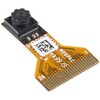
。Description。The HM01B0 from Himax Imaging is an ultra low power CMOS Monochrome Image Sensor that enables the integration of an "Always On" camera for computer vision applications such as gestures, intelligent ambient light and proximity sensing, tracking and object identification. The sensor allows the sensor to consume very low power of <2mW at QVGA 30FPS. This low power consumption and vision applications camera comes with a ribbon cable that mates to the camera connector populated on the following products:MicroMod Machine Learning Carrier Board。Artemis Development Kit。Edge Development Board - Apollo3 Blue。The HM01B0 contains 320×320 pixel resolution and supports a 320×240 window mode which can be readout at a maximum frame rate of 60FPS, and a 2×2 monochrome binning mode with a maximum frame rate of 120FPS. The video data is transferred over a configurable 1bit, 4bit or 8bit interface with support for frame and line synchronization. The sensor integrates black level calibration circuit, automatic exposure and gain control loop, self-oscillator and motion detection circuit with interrupt output to reduce host computation and commands to the sensor to optimize the system power consumption.。Features。Image Sensor。Ultra Low Power Image Sensor(ULPIS)designed for Always On vision devices and applications。High sensitivity 3.6μ BrightSenseTM pixel technology。320×320 active pixel resolution with support for QVGA window, vertical flip and horizontal mirror readout。Programmable black level calibration target, frame size, frame rate, exposure, analog gain(up to 8x)and digital gain(up to 4x)。Automatic exposure and gain control loop with support for 50 / 60Hz flicker avoidance。Flexible 1bit, 4bit and 8bit video data interface with video frame and line sync。Motion Detection circuit with programmable ROI and detection threshold with digital output to serve as an interrupt。On-chip self oscillator。I2C 2-wire serial interface for register access。High CRA for low profile module design。Sensor Parameters。Active Pixel Array 320×320。Pixel Size 3.6 μm×3.6 μm。Full Image Area 1152 μm×1152 μm。Diagonal(Optical Format)1.63 mm(1/11″)。Scan Mode:Progressive。Shutter Type:Electronic Rolling Shutter。Frame Rate MAX 51 fps @ 320×320, 60 fps @ 320×240(QVGA)。CRA(maximum)30℃。Sensor Specifications。Supply Voltage:Analog - 2.8 V, Digital - 1.5V(Internal LDO:1.5V - 2.8V), I/O - 1.5 - 2.8V。Input Reference Clock:3 - 50 MHz。Serial Interface(I2C):2-wire, 400 KHz max.。Video Data Interface:1b, 4b, 8b with frame / line SYNC。Output Clock Rate MAX:50 MHz for 1bit, 12.5 MHz for 4bit, 6.25 MHz for 8bit。Est. Power Consumption(include IO with 5pF load):QVGA 60FPS(Typical)<4 mW。QVGA 30FPS(Typical)<2 mW
アズワン品番67-0427-08
1個
¥2,998
税込¥3,298
33日以内出荷

Description。The SparkFun LTE CAT M1/NB-IoT Shield equips your Arduino or Arduino-compatible microcontroller with access to data networks across the globe. This shield adds wireless, high-bandwidth cellular functionality to your IoT project while maintaining low power consumption and small footprint. The SparkFun LTE CAT M1/NB-IoT Shield is based off the Arduino R3's footprint that allows you to easily incorporate it with favorite Arduino-based device.。At the heart of the LTE Cat M1/NB-IoT shield is u-blox SARA-R410M-02B LTE Cat M1/NB-IoT modem. Cat M1(Category M1)and NB-IoT(Narrowband IoT)are both Low Power Wide Area Network(LPWAN)technologies that are designed to provide cellular communication to small IoT devices. They operate on LTE network bands just like most smartphones, and should be supported by most cellular network carriers. The u-blox SARA-R4 module communicates over UART via simple AT command set. We've provided library to help you get started with everything from sending SMS text messages to communicating with servers over TCP/IP connection. Additionally, both the module and library support an I2C GPS interface via Qwiic connector, so you can plug in u-blox GPS module and start remotely tracking your project.。Each SparkFun LTE CAT M1/NB-IoT Shield also includes ceramic, Molex 1462000001 SMD antenna. The antenna has gain of 3.8dBi around 1.7GHz to 2.7GHz. However, if you would prefer to use an external antenna, we have provided U.FL connector that can be utilized by simply slicing through jumper with hobby knife.。Please be aware that there are few extra parts required to get this shield fully functioning, other than an Arduino-based device. First, you'll need to supply your own SIM card, such as this one from Hologram(we do also offer this shield with an included one as well)and your own headers which will need to be soldered on.。Note:。Be sure to check the。Hardware Overview。section in the Hookup Guide for compatible GPS modules. The onboard Qwiic connector is only designed to support u-blox-based GPS modules. It does not support any other GPS modules or sensors. We are continuing to add more modules so be sure to check back every so often to find out more!。Need custom board?。This component can be found in SparkFun's La Carte board builder. You can have custom design fabricated with this component and your choice of hundreds of other sensors, actuators and wireless devices delivered to you in just few weeks.。Get Started with the SparkFun LTE CAT M1/NB-IoT Shield Guide。Documents。Schematic。Eagle Files。Hookup Guide。Datasheets。SARA-R4。Ceramic Antenna。SARA-R4 AT Command Set。Arduino Library。GitHub
アズワン品番67-0420-75
1個
¥24,980
税込¥27,478
33日以内出荷

Description。The SparkFun Artemis Development Kit is the latest board to be released around the SparkFun Artemis Module and it allows access to more software development features than previous Artemis based boards. This Kit includes the SparkFun Artemis DK board as well as the accessories(Himax camera USB-C cable)needed to get started right away. Recommended software used to program the Artemis DK are the Arduino IDE, Arm(R)Mbed(TM)OS(Studio and CLI), and AmbiqSDK. An updated USB interface(MKL26Z128VFM4 Arm(R)Cortex(R)-M0+ MCU, from NXP)allows the Artemis Dev Kit to act as:Mass Storage Device(MSD):Used to provide drag and drop programming to the Artemis Module.。Human Interface Device(HID):Used for the debugging interface to the Artemis Module.。Communication Port(COM):Used to provide a serial communication UART between the Artemis and the USB connection(PC).。The Artemis Module provides a Cortex(R)-M4F with BLE 5.0 running at 48MHz with an available 96MHz turbo mode and power as low as 6uA per MHz(less than 5mW). The SparkFun Artemis Module is fully FCC/IC/CE certified with 1M flash and 384k RAM you'll have plenty of room for your code. The flexibility of the Artemis module starts with our Arduino core. You can program and use the Artemis module just like you would an Uno or any other Arduino. Additional functionality stems from the ability of the Artemis Dev kit to run RTOS such as the Arm Mbed OS, or the AmbiqSDK.。Attached to the。"Qwiic"。I2C bus, we've added a LIS2DH12TR MEMS accelerometer(for things like gesture recogntion), a digital MEMS microphone, and an edge camera connector for the Himax CMOS imaging camera to experiment with always-on voice commands, and image recognition with TensorFlow and machine learning. All of the Artemis Development Kit pins are broken out to 0.1" spaced female headers(i.e. connectors). There are also two rows of breakout pins with 0.1" pitch spacing for headers; and a 0.08" pitch spacing to clip on IC-hooks, used by most logic analyzers. Additionally the Silk on the back of the Artemis DK acts as a chart to show pins by functionality(peripherals, ADC, PWM, UART0, UART1)and act as an aid while developing software. The board is powered programmed via USB-C, and includes a Qwiic connector to make I2C easy and is fully compatible with SparkFun's Arduino core to be programmed under the Arduino IDE.。Get Started With the SparkFun Artemis Development Kit Guide。Features。Artemis Dev Kit。Compatible with Arduino, Mbed(TM)OS, and AmbiqSDK Development Programs。Power:5V Provided Through the USB-C Connector。1.8V, 3.3V, and 5V Available on Power Header。Interface Chip(MKL26Z128VFM4 ARM(R)Cortex(R)-M0+ MCU):Drag and Drop Programming。SWD Interface。JTAG Programming PTH。Artemis Module:Apollo3 ARM(R)Cortex(R)-M4F MCU。BLE 5.0 with FCC Certification。24 Breakout I/O Pins。Eight 14-bit ADC Pins。Eighteen 16-bit PWM Pins。Two Independent UART Ports。Three Peripheral I2C/SPI Buses。JTAG Programming PTH。Sensors:3-axis Accelerometer(LIS2DH12)。PDM Microphone(SPH0641LM4H-1)。Camera Connector(for the Himax HM01B0 Camera)。Qwiic Connector。On Primary I2C Bus。Himax HM01B0 Camera。Image Sensor。Ultra Low Power Image Sensor(ULPIS)designed for Always On vision devices and applications。High sensitivity 3.6μ BrightSenseTM pixel technology。320×320 active pixel resolution with support for QVGA window, vertical flip and horizontal mirror readout。Programmable black level calibration target, frame size, frame rate, exposure, analog gain(up to 8x)and digital gain(up to 4x)。Automatic exposure and gain control loop with support for 50 / 60Hz flicker avoidance。Flexible 1bit, 4bit and 8bit video data interface with video frame and line sync。Motion Detection circuit with programmable ROI and detection threshold with digital output to serve as an interrupt。On-chip self oscillator。I2C 2-wire serial interface for register access。High CRA for low profile module design。Sensor Parameters。Active Pixel Array 320×320。Pixel Size 3.6 μm×3.6 μm。Full Image Area 1152 μm×1152 μm。Diagonal(Optical Format)1.63 mm(1/11″)。Color Filter Array Monochrome and Bayer。Scan Mode:Progressive。Shutter Type:Electronic Rolling Shutter。Frame Rate MAX 51 fps @ 320×320, 60 fps @ 320×240(QVGA)。CRA(maximum)30℃。Sensor Specifications。Supply Voltage:Analog - 2.8 V, Digital - 1.5V(Internal LDO:1.5V - 2.8V), I/O - 1.5 - 2.8V。Input Reference Clock:3 - 50 MHz。Serial Interface(I2C):2-wire, 400 KHz max.。Video Data Interface:1b, 4b, 8b with frame / line SYNC。Output Clock Rate MAX:50 MHz for 1bit, 12.5 MHz for 4bit, 6.25 MHz for 8bit。Est. Power Consumption(include IO with 5pF load):QVGA 60FPS(Typical)<4 mW。QVGA 30FPS(Typical)<2 mW
アズワン品番67-0424-56
1個
¥12,980
税込¥14,278
33日以内出荷

Description。The SparkFun ProtoShield Kit lets you customize your own Arduino shield using whatever circuit you can come up with and then test it to make sure everything is working the way it should! The SparkFun ProtoShield Kit is based off the Arduino R3's footprint that allows you to easily incorporate it with favorite Arduino-based device.。One of our favorite features with this version of the ProtoShield Kit is the solderable-like breadboard prototyping area! Half of this area was designed with a breadboard in mind. On the underside of the shield you will be able to see open jumper pads between each through hole to make a connection like a breadboard. Once you add a component, simply add a solder jumper between holes to make a connection. For those that prefer the standard prototyping pads, we left the other side(near the BlueSMiRF and Serial UART ports)as is.。We have also moved the prototype testing components(those used to make sure your circuit works effectively)off of the "mainland" of the shield and onto a ProtoSnap styled, removable PCB. On this test area you will find soldering areas for the two yellow 3mm LEDs(as well as pins to control and power them), two 330 Ohm resistors, a 10K Ohm resistor, and a pushbutton.。Note:。Since this product is a kit, assembly and a basic knowledge of soldering will be required. The SparkFun ProtoShield Kit does not come pre-assembled.。Get Started With the SparkFun ProtoShield Kit Guide。Features。Arduino R3 Footprint。Soldering Kit。Solderable-Like Breadboard。BlueSMiRF or Comparable 6-pin Pins。Detachable Test Area
アズワン品番67-0422-25
1個
¥3,298
税込¥3,628
33日以内出荷
関連キーワード