「loc line」の検索結果


Description。This is the PICkit 4, the official programmer from Microchip. The PICkit 4 allows debugging and programming of PIC(R), dsPIC(R), AVR, SAM and CEC flash microcontrollers and MPUs using the powerful graphical user interface of the MPLAB X Integrated Development Environment(IDE). The MPLAB PICkit 4 is connected to a PC using a high-speed 2.0 USB interface and can be connected to the target via an 8-pin Single In-Line(SIL)connector. The connector uses two device I/O pins and the reset line to implement in-circuit debugging and In-Circuit Serial Programming(TM)(ICSP(TM)). An additional micro SD card slot and the ability to be self-powered from the target means you can take your code with you and program on the go. Comes with a USB to micro-B USB cable.。Features。Powered by a high-speed USB 2.0, no external power required。Real-time execution。MPLAB X IDE compatible(free copy included)。Built-in over-voltage/short circuit monitor。Firmware upgradeable from PC/web download。Fully enclosed。Target voltage of 1.20V to 5.5V。Can supply up to 50mA of power to the target。Minimal current consumption at <100μA from target。Diagnostic LEDs(power, busy, error)。Read/write program and data memory of microcontroller。Erase of program memory space with verification。Freeze-peripherals at breakpoint。8-pin single in-line header supports advanced interfaces such as 4-wire JTAG and Serial Wire Debug with streaming Data Gateway。Backward compatible for demo boards, headers and target systems using 2-wire JTAG and ICSP
アズワン品番67-0425-08
1個
¥37,980
税込¥41,778
欠品中

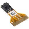
。Description。The HM01B0 from Himax Imaging is an ultra low power CMOS Monochrome Image Sensor that enables the integration of an "Always On" camera for computer vision applications such as gestures, intelligent ambient light and proximity sensing, tracking and object identification. The sensor allows the sensor to consume very low power of <2mW at QVGA 30FPS. This low power consumption and vision applications camera comes with a ribbon cable that mates to the camera connector populated on the following products:MicroMod Machine Learning Carrier Board。Artemis Development Kit。Edge Development Board - Apollo3 Blue。The HM01B0 contains 320×320 pixel resolution and supports a 320×240 window mode which can be readout at a maximum frame rate of 60FPS, and a 2×2 monochrome binning mode with a maximum frame rate of 120FPS. The video data is transferred over a configurable 1bit, 4bit or 8bit interface with support for frame and line synchronization. The sensor integrates black level calibration circuit, automatic exposure and gain control loop, self-oscillator and motion detection circuit with interrupt output to reduce host computation and commands to the sensor to optimize the system power consumption.。Features。Image Sensor。Ultra Low Power Image Sensor(ULPIS)designed for Always On vision devices and applications。High sensitivity 3.6μ BrightSenseTM pixel technology。320×320 active pixel resolution with support for QVGA window, vertical flip and horizontal mirror readout。Programmable black level calibration target, frame size, frame rate, exposure, analog gain(up to 8x)and digital gain(up to 4x)。Automatic exposure and gain control loop with support for 50 / 60Hz flicker avoidance。Flexible 1bit, 4bit and 8bit video data interface with video frame and line sync。Motion Detection circuit with programmable ROI and detection threshold with digital output to serve as an interrupt。On-chip self oscillator。I2C 2-wire serial interface for register access。High CRA for low profile module design。Sensor Parameters。Active Pixel Array 320×320。Pixel Size 3.6 μm×3.6 μm。Full Image Area 1152 μm×1152 μm。Diagonal(Optical Format)1.63 mm(1/11″)。Scan Mode:Progressive。Shutter Type:Electronic Rolling Shutter。Frame Rate MAX 51 fps @ 320×320, 60 fps @ 320×240(QVGA)。CRA(maximum)30℃。Sensor Specifications。Supply Voltage:Analog - 2.8 V, Digital - 1.5V(Internal LDO:1.5V - 2.8V), I/O - 1.5 - 2.8V。Input Reference Clock:3 - 50 MHz。Serial Interface(I2C):2-wire, 400 KHz max.。Video Data Interface:1b, 4b, 8b with frame / line SYNC。Output Clock Rate MAX:50 MHz for 1bit, 12.5 MHz for 4bit, 6.25 MHz for 8bit。Est. Power Consumption(include IO with 5pF load):QVGA 60FPS(Typical)<4 mW。QVGA 30FPS(Typical)<2 mW
アズワン品番67-0427-08
1個
¥2,998
税込¥3,298
翌々日出荷

Description。The XBee3 Thing Plus is an ultra capable and easy way for getting into wireless device development. The combination of XBee and Qwiic in a space conscious design represents a much needed update to our XBee offering. With 20 I/O pins and Lithium Polymer Ion battery management, the XBee3 Thing Plus has all the basics for quickly prototyping or developing a connected device such as a remote sensor. The Qwiic connector and JST connector for the battery make for a solder-less option when working with the board which shortens setup time.。The new XBee3 Micro Module provides the classic all-but plug and play 802.15.4 2.4GHz wireless connection(Zigbee 3.0 Protocol)that makes it so desirable, but with a new addition of being programmable with MicroPython(32KB of memory available for it). RF data rates up to 250 Kbps and 200ft indoor ranges and up to 4000ft line-of-sight outdoor range. Communicating with/Configuring the module happens via an AT Command set or the Digi API, X-CTU, both locally or over-the-air. There's even a mobile version of X-CTU now; Digi XBee(R)Mobile.。This variation features a U.FL antenna connector for longer range communications. Check out the related products for compatible antennas.。Get Started With the SparkFun XBee3 Thing Plus Guide。Features。XBee3 Micro Module。Silicon Labs EFR32MG SoC。250Kbps RF, 1Mbps Serial data rates。Indoor/Urban range up to 200 ft(60 m)。Outdoor/RF Line of Sight range up to 4000 ft(1200 m)。+8 dBm transmit power。-103 dBm receiver sensitivity。UART, I2C, SPI Interfaces(SPI currently not available at this time, but broken out on the board)。ISM 2.4GHz Frequency Band(802.15.4)。1MB of memory, 128KB RAM(32KB available for MicroPython)。20 GPIO Pins。Configurable via X-CTU or AT Command set via both USB and Wirelessly(second XBee 3 device required for wireless configuration unless you're using the mobile app)。Qwiic Compatible。On-board charging circuit and connector for 3.3v Lithium Polymer Ion Batteries(see related products for compatible batteries)。2.6VDC - 3.6VDC supply voltage。U.FL Antenna Connector
アズワン品番67-0429-55
1個
¥11,980
税込¥13,178
翌々日出荷

Description。The XBee3 Thing Plus is an ultra-capable and easy way for getting into wireless device development. The combination of XBee and Qwiic in a space-conscious design represents a much-needed update to our XBee offering. With 20 I/O pins and Lithium-Polymer Ion battery management, the XBee3 Thing Plus has all the basics for quickly prototyping or developing a connected device such as a remote sensor. The Qwiic connector and JST connector for the battery make for a solder-less option when working with the board which shortens setup time.。The new XBee3 Micro Module provides the classic, near plug and play 802.15.4 2.4GHz wireless connection(Zigbee 3.0 Protocol)that makes it so desirable, but with a new addition of being programmable with MicroPython(32KB of memory available for it). RF data rates up to 250Kbps and 200 ft indoor ranges and up to 4000 ft line-of-sight outdoor range. Communicating with/Configuring the module happens via an AT Command set or the Digi API, X-CTU, both locally or over-the-air. There's even a mobile version of X-CTU now; Digi XBee(R)Mobile.。Note:This variation uses a chip antenna and is not compatible with external antennas.。Get Started With the SparkFun XBee3 Thing Plus Guide。Features。XBee3 Micro Module。Silicon Labs EFR32MG SoC。250Kbps RF, 1Mbps Serial data rates。Indoor/Urban range up to 200 ft(60 m)。Outdoor/RF Line of Sight range up to 4000 ft(1200 m)。+8 dBm transmit power。-103 dBm receiver sensitivity。UART, I2C, SPI Interfaces(SPI currently not available at this time, but broken out on the board)。ISM 2.4GHz Frequency Band(802.15.4)。1MB of memory, 128KB RAM(32KB available for MicroPython)。20 GPIO Pins。Configurable via X-CTU or AT Command set via both USB and Wirelessly(second XBee 3 device required for wireless configuration unless you're using the mobile app)。Qwiic Compatible。On-board charging circuit and connector for 3.3v Lithium Polymer Ion Batteries(see related products for compatible batteries)。2.6VDC - 3.6VDC supply voltage。On-board Chip Antenna
アズワン品番67-0429-57
1個
¥12,980
税込¥14,278
翌々日出荷

Description。The LIDAR-Lite v4 LED sensor is the next step in the LIDAR-Lite line. A small, lightweight, low-power optical ranging sensor. It's the first to incorporate ANT profile wireless networking technology into an optical sensor. Its built-in nRF52840 processor means that developers can create custom applications, or be operated as a stand-alone device right out of the box by using the preloaded stock application.。Like the LIDAR-Lite v3 and LIDAR-Lite v3HP sensors; it can also be directly connected to an external micro-controller running a custom user application. As such, it provides a highly adaptable option for OEM and maker applications in robotics, Internet of Things, and unmanned vehicles ― or any application where an ultrasonic sensor might otherwise be used. It's perfect as the basic building block for applications where wireless capabilities, small size, light weight, low power consumption and high performance are important factors in a short-range, 10-meter, optical distance measuring sensor.。The LIDAR-Lite v4 requires an external 5VDC power source and soldering is required. This Time-of-Flight ranging module uses a LED and optics for ranging. It does not use a laser; therefore, it is inherently eye-safe under normal usage.。Features。Resolution:1 cm。Measurement repeatability:As measured indoors to a 90% reflective target。1 cm is equivalent to 1 standard deviation。Using "high accuracy" mode, with averaging:+/- 1 cm to 2 meters。+/- 2 cm to 4 meters。+/- 5 cm to 10 meters。Range:5 cm to 10 meters(as measured from back of unit)。Update rate:I2C = >200 Hz typical。ANT(R)= up to 200 Hz to a 90% target indoors at 2m in normal operating mode。Interface:I2C or ANT; user configurable for SPI using the Nordic SDK。Power(operating voltage):4.75 - 5.25 VDC。Current consumption:2mA idle, 85mA during acquisition。Operating temperature:-20 to 60° C。LED wavelength:940 nm。Beam divergence:4.77°。Optical aperture:14.9 mm。Unit size(HxWxD):2.1"×0.8"×0.9"(52.2×21.2×24.0 mm)。Weight:14.6 g(0.5 oz)
アズワン品番67-0427-09
1個
¥18,980
税込¥20,878
翌々日出荷

Description。The MicroMod Machine Learning Carrier Board combines some of the features of our SparkFun Edge Board and SparkFun Artemis boards, but allows you the freedom to explore with any processor in the MicroMod lineup without the need for a centra
アズワン品番67-0423-04
1個
¥4,798
税込¥5,278
翌々日出荷

Description。This is a two pin, compact surface mount JST connector. We really like the solid locking feeling and high current rating on these small connectors. We use these all the time as battery connectors.
アズワン品番67-0425-09
1個
¥209
税込¥230
33日以内出荷

。Description。The SparkFun RV-8803 Real Time Clock Module is a Qwiic-enabled breakout board for the RV-8803 RTC. The RV-8803 boasts some impressive features including a temperature compensated crystal providing extremely precise time-keeping, low power consumption, and time stamp event input along with a user-programmable timing offset value. The RV-8803 also has an improved I2C interface compared to the RV-1805 RTC that removes the need to sequence commands/writes to the device. Best of all, the temperature compensation comes factory calibrated. Utilizing our handy Qwiic system so no soldering is required to connect it to the rest of your system. However, we still have broken out 0.1"-spaced pins in case you prefer to use a breadboard.。Adding a real-time clock to your project is the perfect way to get more accurate data; timing or otherwise. Using the Qwiic connector makes for a fast, solid way to incorporate this into your project. The RTC module has counters for hundredths of seconds, seconds, minutes, hours, date, month, year and weekday with a number of alarm and interrupt settings available as well. Plus the large operating temperature range(-40 to +105℃)and temperature compensated crystal makes for a good addition for field applications or harsh environments.。The SparkFun Qwiic Connect System is an ecosystem of I2C sensors, actuators, shields and cables that make prototyping faster and less prone to error. All Qwiic-enabled boards use a common 1mm pitch, 4-pin JST connector. This reduces the amount of required PCB space, and polarized connections mean you can't hook it up wrong.。Get Started with the SparkFun RV-8803 Real Time Clock Module Guide。Features。Factory Calibrated Temperature Compensation。High Time Accuracy。±1.5 ppm 0 to +50℃。±3.0 ppm -40 to +85℃。±7.0 ppm +85 to +105℃。1.5V to 5.5V Operating Voltage Range。240nA @ 3.3v Low-Power Consumption。I2C Address:0x32。Periodic Countdown Timer Interrupt function。Periodic Time Update Interrupt function(seconds, minutes)。Alarm Interrupts for weekday or date, hour and minute settings。External Event Input with Interrupt and Time Stamp function。Programmable Clock Output pin for peripheral devices.。Operating temperature range:-40 to +105℃。2x Qwiic Connectors
アズワン品番67-0420-10
1個
¥3,698
税込¥4,068
翌々日出荷

Description。The AS358P is a great, easy-to-use dual-channel Op-amp. Op-amps have so many applications we figured we should probably carry at least one in a DIP package. AS358P applications include transducer amplifiers, DC gain blocks and all the conv
アズワン品番67-0421-48
1個
¥219
税込¥241
33日以内出荷

Description。The Elektor MIT App Inventor Bundle is a kit built to help learn about developing apps for Android compatible mobile devices using the MIT App Inventor online development environment. MIT App Inventor projects can be in either standalone mode or use an external processor. In standalone mode, the developed application runs only on the mobile device(e.g. Android). In external processor-based applications, the mobile device communicates with an external microcontroller-based processor, such as Raspberry Pi, Arduino, ESP8266, ESP32, etc.。The kit comes with a book and a selection of parts that correspond with a number of projects. Check out the features and Includes tab for more information.。Features。Projects Include:Using the text-to-speech component。Intonating a received SMS message。Sending SMS messages。Making telephone calls using a contacts list。Using the GPS and Pin-pointing our location on a map。Speech recognition and speech translation to another language。Controlling multiple relays by speech commands。Projects for the Raspberry Pi, ESP32 and Arduino using Bluetooth and Wi-Fi。MIT APP Inventor and Node-RED projects for the Raspberry Pi
アズワン品番67-0424-73
1個
¥22,980
税込¥25,278
翌々日出荷

Description。The SparkFun RTK Surveyor is an easy to use GNSS receiver for centimeter-level positioning. Perfect for surveying, this preprogrammed device can also be used for autonomous driving, navigation, asset tracking and any other application where there is a clear view of the sky. The RTK Surveyor can also be used as a base station. With the flick of a switch, two RTK Surveyors can be used to create an RTK system capable of 14mm horizontal positional accuracy. The built-in Bluetooth(R)connection via an ESP32 WROOM enables the user to use the RTK Surveyor with their choice of GIS application on a phone or tablet. The built in battery allows field use for up to four hours and is compatible with common USB battery banks.。This device can be used in four modes:GNSS Positioning(~30cm accuracy)。GNSS Positioning with RTK(1.4cm accuracy)。GNSS Base Station。GNSS Base Station NTRIP Server。In Position mode the device receives L1/L2 signals from a user-provided antenna and the high-grade GNSS receiver provides lat/long and altitude with accuracies around 300mm.。In Positioning with RTK mode the device receives L1/L2 signals from the antenna and correction data from a base station. The correction data can be obtained from a cellular link to online correction sources or over a radio link to a 2nd RTK Surveyor setup as a base station.。In Base Station mode the device is mounted to a temporary position(like a tripod)and begins transmitting correction data over a radio or internet connection. A base is often used in conjunction with a second unit set to 'Positioning with RTK' to obtain the 14mm relative accuracy.。In Base Station NTRIP Server mode the device is mounted to a semi or permanently fixed position(like a roof)and connects over WiFi to transmit the correction data to a NTRIP caster so that any rover can access the correction data over a cellular or internet connection. This type of base is a very easy way to setup a very precise absolute correction source.。Two cables are provided with the RTK Surveyor allowing a user to plug on our easy to use Serial Telemetry Radios or their own radio link. If a local correction source is within 10km, a user can also use their phone to provide correction data over the Bluetooth(R)link(no external radio needed!).。Note:The SparkFun RTK Surveyor is just the enclosed device and does NOT include an antenna, serial telemetry radio, or associated mounting pieces. These items will need to be purchased separately from the Hookup Accessories below.。Get Started With the SparkFun RTK Surveyor Guide。Features。GNSS Receiver:ZED-F9P。Concurrent reception of GPS, GLONASS, Galileo and BeiDou。Receives both L1C/A and L2C bands。Current:68mA - 130mA(varies with constellations and tracking state)。Time to First Fix:25s(cold), 2s(hot)。Max Navigation Rate:PVT(basic location over UBX binary protocol)- 25Hz。RTK - 20Hz。Raw - 25Hz。Horizontal Position Accuracy:2.5m without RTK。0.010m with RTK。Max Altitude:50km(31 miles)。Max Velocity:500m/s(1118mph)。Bluetooth(R)Transceiver:ESP32 WROOM。Xtensa(R)dual-core 32-bit LX6 microprocessor。Up to 240MHz clock frequency。16MB of flash storage。520kB internal SRAM。Integrated 802.11 BGN WiFi transceiver。Integrated dual-mode Bluetooth(R)(classic and BLE)。Hardware accelerated encryption(AES, SHA2, ECC, RSA-4096)。2.5 μA deep sleep current。Overall Device。Internal Battery:LiPo 1000mAh with 500mA charging。Radio Port:3.3V TTL Serial(57600bps RTCM TX/RX)。Data Port:3.3V TTL Serial(115200bps NMEA)。Weight:132g(entire device including battery)。Dimensions:118mm×79mm×30mm(4.7in×3.1in×1.2in)。1x Qwiic Connector。1x microSD Socket for optional logging。Changes:This version(which replaces SPX-17369)uses a reinforced edge mount SMA connector for better resiliency when a fixed 'stub' antenna is used.
アズワン品番67-0423-95
1個
¥99,980
税込¥109,978
翌々日出荷

Description。The SparkFun NEO-M9N GPS Breakout is a high quality GPS board with equally impressive configuration options including SMA. The NEO-M9N module is a 92-channel u-blox M9 engine GNSS receiver, meaning it can receive signals from the GPS, GLONASS, Galileo, and BeiDou constellations with ~1.5 meter accuracy. This breakout supports concurrent reception of four GNSS. This maximizes position accuracy in challenging conditions increasing, precision and decreases lock time; and thanks to the onboard rechargeable battery, you'll have backup power enabling the GPS to get a hot lock within seconds! Additionally, this u-blox receiver supports I2C(u-blox calls this Display Data Channel)which makes it perfect for the Qwiic compatibility so we don't have to use up our precious UART ports. Utilizing our handy Qwiic system, no soldering is required to connect it to the rest of your system. However, we still have broken out 0.1"-spaced pins in case you prefer to use a breadboard.。The NEO-M9N module detects jamming and spoofing events and can report them to the host, so that the system can react to such events. A SAW(Surface Acoustic Wave)filter combined with an LNA(Low Noise Amplifier)in the RF path is integrated into the NEO-M9N module which allows normal operation even under strong RF interferences.。U-blox based GPS products are configurable using the popular, but dense, windows program called u-center. Plenty of different functions can be configured on the NEO-M9N:baud rates, update rates, geofencing, spoofing detection, external interrupts, SBAS/D-GPS, etc. All of this can be done within the SparkFun Arduino Library!。The SparkFun NEO-M9N GPS Breakout is also equipped with an on-board rechargeable battery that provides power to the RTC on the NEO-M9N. This reduces the time-to-first fix from a cold start(~24s)to a hot start(~2s). The battery will maintain RTC and GNSS orbit data without being connected to power for plenty of time.。This product requires an antenna:Be sure to check out the related products/hookup accessories and pick a suitable SMA antenna for your project.。The SparkFun Qwiic Connect System is an ecosystem of I2C sensors, actuators, shields and cables that make prototyping faster and less prone to error. All Qwiic-enabled boards use a common 1mm pitch, 4-pin JST connector. This reduces the amount of required PCB space, and polarized connections mean you can't hook it up wrong.。The NEO-M9N GPS Breakout can also be automatically detected, scanned, configured, and logged using the OpenLog Artemis datalogger system. No programming, soldering, or setup required!。Get Started With the SparkFun NEO-M9N GPS Guide。Features。Integrated SMA connector for use with antenna of your choice。92-Channel GNSS Receiver。1.5m Horizontal Accuracy。25Hz Max Update Rate(four concurrent GNSS)。Time-To-First-Fix:Cold:24s。Hot:2s。Max Altitude:80,000m。Max G:≦4。Max Velocity:500m/s。Velocity Accuracy:0.05m/s。Heading Accuracy:0.3 degrees。Time Pulse Accuracy:30ns。3.3V VCC and I/O。Current Consumption:~31mA Tracking GPS+GLONASS。Software Configurable。Geofencing。Odometer。Spoofing Detection。External Interrupt。Pin Control。Low Power Mode。Many others!。Supports NMEA, UBX, and RTCM protocols over UART or I2C interfaces
アズワン品番67-0423-87
1個
¥16,980
税込¥18,678
翌々日出荷

Description。The SparkFun RTK Express is an easy to use GNSS receiver for centimeter-level positioning. Perfect for surveying, logging, and all types of post processing, this preprogrammed device can also be used for autonomous driving, navigation, asset tracking and any other application where there is a clear view of the sky. The RTK Express can also be used as a base station. With the press of a button, two RTK Expresses can be used to create an RTK system capable of 14mm horizontal positional accuracy. The built-in Bluetooth(R)connection via an ESP32 WROOM enables the user to use the RTK Express with their choice of GIS application on a phone or tablet. The built in battery allows for over five hours of field use and is compatible with common USB battery banks.。We took all the lessons from the RTK Surveyor and built the RTK Express. The RTK Express is built upon the same ZED-F9P u-blox receiver as the original RTK Surveyor so you can expect the same incredible performance and rich feature set. The embedded display allows for immediate feedback of horizontal positional accuracy, satellites in view, logging status, survey-in status, battery level, Bluetooth(R)MAC, etc. The rocker switches found on the original have been replaced by keypad buttons. We increased the battery to 1300mAh for a longer run time. The internal switches have been replaced by a digital Mux allowing for some really exciting applications including event triangulation. More ESD protection was added to protect the RF path, and we even threw in an accelerometer for digital leveling in the field.。This device can be used in four modes:GNSS Positioning(~30cm accuracy)。GNSS Positioning with RTK(1.4cm accuracy)。GNSS Base Station。GNSS Base Station NTRIP Server。In Position mode the device receives L1/L2 signals from a user-provided antenna and the high-grade GNSS receiver provides lat/long and altitude with accuracies around 300mm.。In Positioning with RTK mode the device receives L1/L2 signals from the antenna and correction data from a base station. The correction data can be obtained from a cellular link to online correction sources or over a radio link to a second RTK Surveyor/Express setup as a base station.。In Base Station mode the device is mounted to a temporary position(like a tripod)and begins transmitting correction data over a radio or Internet connection. A base is often used in conjunction with a second unit set to 'Positioning with RTK' to obtain the 14mm relative accuracy. The RTK Surveyor and RTK Express are interchangeable as a Base Station; an RTK Surveyor can be a base for an RTK Express and vice versa.。In Base Station NTRIP Server mode the device is mounted to a semi or permanently fixed position(like a roof)and connects over WiFi to transmit the correction data to a NTRIP caster so that any rover can access the correction data over a cellular or Internet connection. This type of base is a very easy way to set up a very precise absolute correction source.。Two cables are provided with the RTK Express allowing a user to plug in our easy to use Serial Telemetry Radios or their own radio link. If a local correction source is within 10km, a user can also use their phone to provide correction data over the Bluetooth(R)link(no external radio needed!).。Note:The SparkFun RTK Express is just the enclosed device and does NOT include an antenna, serial telemetry radio, or associated mounting pieces. These items will need to be purchased separately from the Hookup Accessories below.。Get Started With the SparkFun RTK Express Guide。Features。GNSS Receiver:ZED-F9P。Concurrent reception of GPS, GLONASS, Galileo and BeiDou。Receives both L1C/A and L2C bands。Current:68mA - 130mA(varies with constellations and tracking state)。Time to First Fix:25s(cold), 2s(hot)。Max Navigation Rate:PVT(basic location over UBX binary protocol)- 25Hz。RTK - 20Hz。Raw - 25Hz。Horizontal Position Accuracy:2.5m without RTK。0.010m with RTK。Max Altitude:50km(31 miles)。Max Velocity:500m/s(1118mph)。Bluetooth(R)Transceiver:ESP32 WROOM。Xtensa(R)dual-core 32-bit LX6 microprocessor。Up to 240MHz clock frequency。4MB of flash storage。520kB internal SRAM。Integrated 802.11 BGN WiFi transceiver。Integrated dual-mode Bluetooth(R)(classic and BLE)。Hardware accelerated encryption(AES, SHA2, ECC, RSA-4096)。2.5 μA deep sleep current。Overall Device。Internal Battery:LiPo 1300mAh with 500mA charging。Radio Port:3.3V TTL Serial(57600bps RTCM TX/RX)。Data Port:3.3V TTL Serial(115200bps NMEA)。Embedded OLED Display for available satellites, data logging, and more.。Push button controls。Weight:162g(entire device including battery)。Dimensions:132mm×101mm×32mm(5.2in×3.9in×1.2in)。1x Qwiic Connector。Changes:This version(which replaces SPX-18019)uses a reinforced edge mount SMA connector for better resiliency when a fixed 'stub' antenna is used.
アズワン品番67-0423-94
1個
¥129,800
税込¥142,780
翌々日出荷

Description。The SparkFun ZOE-M8Q GPS Breakout is a high accuracy, miniaturized, GPS board that is perfect for applications that don't possess a lot of space. The on-board ZOE-M8Q is a 72-channel GNSS receiver, meaning it can receive signals from the GPS, GLONASS, BeiDou, and Galileo constellations. This increases precision and decreases lock time and thanks to the onboard rechargable battery you'll have backup power enabling the GPS to get a hot lock within seconds! Additionally, this u-blox receiver supports I2C(u-blox calls this Display Data Channel)which made it perfect for the Qwiic compatibility so we don't have to use up our precious UART ports. Utilizing our handy Qwiic system, no soldering is required to connect it to the rest of your system. However, we still have broken out 0.1"-spaced pins in case you prefer to use a breadboard.。U-blox based GPS products are configurable using the popular, but dense, windows program called u-center. Plenty of different functions can be configured on the ZOE-M8Q:baud rates, update rates, geofencing, spoofing detection, external interrupts, SBAS/D-GPS, etc. All of this can be done within the SparkFun Arduino Library. We've also made sure to configure the UART pin grouping on the breakout to an industry standard to insure that it easily connects to a Serial Basic.。The SparkFun ZOE-M8Q GPS Breakout is also equipped with an on-board rechargeable battery that provides power to the RTC on the ZOE-M8Q. This reduces the time-to-first fix from a cold start(~30s)to a hot start(~1s). The battery will maintain RTC and GNSS orbit data without being connected to power for up to five hours. Since the ZOE-M8Q is a tiny GPS receiver and to minimize its footprint, we've added a U.FL connector to allow the use of both large standard ceramic antennas as well as very small chip scale antennas.。Note:The I2C address of the ZOE-M8Q is 0x42 and is software configurable. A multiplexer/Mux is required to communicate to multiple ZOE-M8Q sensors on a single bus. If you need to use more than one ZOE-M8Q sensor consider using the Qwiic Mux Breakout.。The SparkFun Qwiic Connect System is an ecosystem of I2C sensors, actuators, shields and cables that make prototyping faster and less prone to error. All Qwiic-enabled boards use a common 1mm pitch, 4-pin JST connector. This reduces the amount of required PCB space, and polarized connections mean you can't hook it up wrong.。The ZOE-M8Q GPS Breakout can also be automatically detected, scanned, configured, and logged using the OpenLog Artemis datalogger system. No programming, soldering, or setup required!。Get Started With the SparkFun ZOE-M8Q Hookup Guide。Features。72-Channel GNSS Receiver。2.5m Horizontal Accuracy。18Hz Max Update Rate。Time-To-First-Fix:Cold:26s。Hot:1s。Max Altitude:50,000m。Max G:≦4。Max Velocity:500m/s。Velocity Accuracy:0.05m/s。Heading Accuracy:0.3 degrees。Time Pulse Accuracy:30ns。3.3V VCC and I/O。Current Consumption:~29mA Tracking GPS+GLONASS。Software Configurable。Geofencing。Odometer。Spoofing Detection。External Interrupt。Pin Control。Low Power Mode。Many others!。Supports NMEA, UBX, and RTCM protocols over UART or I2C interfaces
アズワン品番67-0423-76
1個
¥11,980
税込¥13,178
翌々日出荷

Description。The Teensy is an amazing and compact development platform in breadboard friendly form factor, but what if you could incorporate it into the Arduino architecture? The Teensy Arduino Shield Adapter allows you to attach your Teensy and utilize your favorite Arduino shields without the requirement of breadboard or any complicated wiring. Needless to say, the Teensy Arduino Shield Adapter is useful tool for upgrading all of your existing Arduino projects to more powerful controller!。As we stated before, the Teensy Arduino Shield Adapter provides basic Arduino compatibility with your run-of-the-mill shield but there are few other fun features that we've added on, as well. These features include Real Time Clock(RTC)battery, JST battery connector, 4-12V barrel jack connector, an ICSP header, and more. Because this board is simply an adapter, there is no special programming required to start working with the adapter. You will, however, need to program the Teensy for any Arduino shield you'd like to work with.。While the adapter design can fit the Teensy LC footprint, it has been designed to fully utilize the features of the Teensy 3.1. Not all of the features available on the adapter are compatible with the LC so please be sure to check the Hookup Guide in the。Documents。section below to ensure functionality for your project. Please keep in mind that this adapter may be incompatible with some 5V Arduino shields. Please check our hookup guide for more information.。Note:The Teensy Arduino Shield Adapter comes as kit and will need to be soldered together.。Note:Due to the requirements of shipping the batteries in this kit, orders may take longer to process and therefore do not qualify for same-day shipping. Additionally, these batteries can not be shipped via Ground or Economy methods to Alaska or Hawaii. Sorry for any inconvenience this may cause.。Features。Arduino R3 Interface。Real Time Clock Battery。JST Battery Connector。Barrel Jack。I2C Jumpers。ICSP Header。DAC Pin Header
アズワン品番67-0424-36
1個
¥3,298
税込¥3,628
翌々日出荷

Description。If you are not needing a lot of power to start your FPGA adventure, or are looking for a more economical option, the Alchitry Cu FPGA Development Board might be the perfect option for you! The Alchitry Cu is a "lighter" FPGA version than the Alchitry Au but still offers something completely unique. FPGAs, or Field-Programmable Gate Arrays, are an advanced development board type for engineers and hobbyists alike to experience the next step in programming with electronics. The Cu truly exemplifies the trend of more affordable and increasingly powerful FPGA boards arriving each year. This board is a fantastic starting point into the world of FPGAs and the heart of your next project. Finally, now that this board is built by SparkFun, we added a Qwiic connector for easy I2C integration!。The Alchitry Cu uses the Lattice iCE40 HX FPGA with 7680 logic cells and is supported by the open source tool chain Project IceStorm. The Cu possesses 79 IO pins with eight general purpose LEDs; a 100MHz on-board clock that can be manipulated internally by the FPGA; a USB-C connector to configure and power the board; and a USB to serial interface for data transfer.。By adding stackable expansion boards similar to shields or HATs called "Elements," the Alchitry Cu is able to expand its own hardware capabilities by adding prototyping spaces, buttons, LEDs, and more!。The SparkFun Qwiic Connect System is an ecosystem of I2C sensors, actuators, shields and cables that make prototyping faster and less prone to error. All Qwiic-enabled boards use a common 1mm pitch, 4-pin JST connector. This reduces the amount of required PCB space, and polarized connections mean you can't hook it up wrong.。Get Started with our Learning FPGA Tutorials。Features。Lattice iCE40-HX8K FPGA - 7680 logic elements。79 IO pins(3.3V logic level)。USB-C to configure and power the board。Eight general purpose LEDs。One button(typically used as a reset)。100MHz on-board clock(can be multiplied internally by the FPGA)。Powered with 5V through USB-C port, 0.1" holes, or headers。USB to serial interface for data transfer(up to 12Mbaud)。Qwiic Connector。Dimensions of 65mm×45mm。。Examples。First FPGA Project - Getting Fancy with PWM。External IO and Metastability
アズワン品番67-0423-08
1個
¥13,980
税込¥15,378
翌々日出荷

。Description。The Alchitry Au is the "gold" standard for FPGA development boards and it's possibly one of the strongest boards of its type on the market. FPGAs, or Field-Programmable Gate Arrays, are an advanced development board type for engineers and hobbyists alike to experience the next step in programming with electronics. The Au continues the trend of more affordable and increasingly powerful FPGA boards arriving each year. This board is a fantastic starting point into the world of FPGAs and the heart of your next project. Finally, now that this board is built by SparkFun, we added a Qwiic connector for easy I2C integration!。The Alchitry Au features a Xilinx Artix 7 XC7A35T-1C FPGA with over 33,000 logic cells and 256MB of DDR3 RAM. The Au offers 102 3.3V logic level IO pins, 20 of which can be switched to 1.8V; Nine differential analog inputs; Eight general purpose LEDs; a 100MHz on-board clock that can be manipulated internally by the FPGA; a USB-C connector to configure and power the board; and a USB to serial interface for data transfer. To make getting started even easier, all Alchitry boards have full Lucid support, a built in library of useful components to use in your project, and a debugger!。By adding stackable expansion boards similar to shields or HATs called "Elements," the Alchitry Au is able to expand its own hardware capabilities by adding prototyping spaces, buttons, LEDs, and more!。The SparkFun Qwiic Connect System is an ecosystem of I2C sensors, actuators, shields and cables that make prototyping faster and less prone to error. All Qwiic-enabled boards use a common 1mm pitch, 4-pin JST connector. This reduces the amount of required PCB space, and polarized connections mean you can't hook it up wrong.。Get Started with our Learning FPGA Tutorials。Features。Artix 7 XC7A35T-1C - 33,280 logic cells。256MB DDR3 RAM。102 IO pins(3.3V logic level, 20 of then can be switched to 1.8V for LVDS)。Nine differential analog inputs(One dedicated, Eight mixed with digital IO)。USB-C to configure and power the board。Eight general purpose LEDs。One button(typically used as a reset)。100MHz on-board clock(can be multiplied internally by the FPGA)。Powered with 5V through USB-C port, 0.1" holes, or headers。USB to serial interface for data transfer(up to 12Mbaud)。Qwiic Connector。Dimensions of 65mm×45mm。。Examples。First FPGA Project - Getting Fancy with PWM。External IO and Metastability
アズワン品番67-0423-09
1個
¥29,980
税込¥32,978
翌々日出荷

Description。If you have ever wanted to get into FPGAs but never knew where to begin, the Alchitry Au FPGA kit from SparkFun provides you with the boards you need to get started! Included in this kit is the Alchitry Au, Alchitry Io Element, Alchitry Br Prototype, and a 4-pack of female headers. The only thing you'll need to supply are a USB-C cable to power and program the Au and Qwiic cables to add I2C accessory integration.。The Alchitry Au, included in this kit, features a Xilinx Artix 7 XC7A35T-1C FPGA with over 33,000 logic cells and 256MB of DDR3 RAM. The Au offers 102 3.3V logic level IO pins, 20 of which can be switched to 1.8V; Nine differential analog inputs; Eight general purpose LEDs; a 100MHz on-board clock that can be manipulated internally by the FPGA; a USB-C connector to configure and power the board; and a USB to serial interface for data transfer. To make getting started even easier, all Alchitry boards have full Lucid support, a built in library of useful components to use in your project, and a debugger!。Thanks to the included Io and Br Element boards also included in this kit, you will also have access to 7-segment LEDs, five momentary push buttons, 24 basic LEDs, and 24 DIP switches, a the broken out header pins, and a large prototyping area!。Get Started with our Learning FPGA Tutorials。Examples。First FPGA Project - Getting Fancy with PWM。External IO and Metastability
アズワン品番67-0424-51
1個
¥39,980
税込¥43,978
翌々日出荷

Description。The SparkFun Qwiic micro:bit Breakout is a board that connects to the BBC micro:bit and expands the capabilities of the development platform by providing access to more pins and allowing for connections to the I2C and SPI buses. This breakout board for the micro:bit's edge connector allows intermediate and advanced users to connect the micro:bit to breadboards and other Qwiic sensors, motors, LEDs and more.。The micro:bit on its own has three digital/analog input/output rings available for you to use initially with alligator clips. With the micro:bit Breakout we have broken out all 21 GPIO, power and ground-to-pin outs in a 0.1" formation and with two individual Qwiic Connectors. With this breakout you will be able to unlock the full potential of your micro:bit!。Note:。No micro:bit or headers are included with this breakout; they will need to be purchased separately. If you would like a micro:bit breakout with headers already soldered on, be sure to check out this board's sibling.。The SparkFun Qwiic Connect System is an ecosystem of I2C sensors, actuators, shields and cables that make prototyping faster and less prone to error. All Qwiic-enabled boards use a common 1mm pitch, 4-pin JST connector. This reduces the amount of required PCB space, and polarized connections mean you can't hook it up wrong.。Get Started with the Qwiic micro:bit Breakout Guide
アズワン品番67-0420-12
1個
¥1,598
税込¥1,758
翌々日出荷

。Description。Passive Infrared(PIR)sensors are great for detecting motion in a small area around the sensor. The 170μA SparkFun EKMC4607112K PIR Breakout is a simple board equipped with an EKM-series PIR sensor from Panasonic(R). The EKM-series PIR sensors are optimized for small movements to offer motion-sensing options for continuously powered applications.。PIR sensors do not return specific distance data but instead monitor for IR light coming from objects in their field of view and will activate their signal when motion is detected in their sensing area, making them perfect for applications such as turning devices on automatically when motion is detected. Applications include home and building automation for energy saving, automated on/off lighting control, security, appliances, and IoT.。Panasonic's low-profile PIR motion sensors(10.9mm versus standard 14.4mm height offer space savings for constrained designs)consist of a lens to create various detection zones, an optical filter to block non-infrared light, pyroelectric sensing elements, electromagnetic shielding to all circuitry, and an impedance converter to get an electrical signal. This PIR sensor offers digital output across 32 zones at 5m detection distance with 90°×90° detection area.。Note:The sensitivity of passive infrared sensors is influenced by environmental conditions, so a performance evaluation test under representative conditions is recommended.。Get Started with the SparkFun PIR Breakout Guide。Features。Operating Voltage:2.3。-。4.0V。170 μA。standby current consumption。Lens diameter - 10.4mm。Lens Height - 10.9mm。5m detection distance。90°×90°(±45°)detection area
アズワン品番67-0427-43
1個
¥4,598
税込¥5,058
翌々日出荷

。Description。The SparkFun Inventor's Kit(SIK)for Arduino Uno is a great way to get started with programming and hardware interaction with the Arduino programming language. The SIK includes everything you need to complete five overarching projects consisting of 16 interconnected circuits that teach everything from blinking an LED to reading sensors. The culminating project is your very own autonomous robot! No previous programming or electronics experience is required to use this kit.。The online guide contains step-by-step instructions with circuit diagrams and hookup tables for building each project and circuit with the included parts. Full example code is provided, new concepts and components are explained at point of use, and troubleshooting tips offer assistance if something goes wrong.。The kit does not require any soldering and is recommended for beginners ages 10 and up who are looking for an Arduino starter kit. For SIK version 4.1 we took an entirely different approach to teaching embedded electronics. In previous versions of the SIK, each circuit focused on introducing a new piece of technology. With SIK v4.1, components are introduced in the context of the circuit you are building, and each circuit builds upon the last, leading up to a project that incorporates all of the components and concepts introduced throughout the guide. With new parts and a completely new strategy, even if you've used the SIK before, you're in for a brand-new experience!。This version of the SIK replaces the SparkFun RedBoard Qwiic with the Arduino Uno(SMD version)and comes without the SIK guidebook and carrying case. With these components being swapped and removed, we were able to reduce the overall size and weight of the kit, making shipping cheaper and easier for anyone ordering internationally.。Note:As stated above, this SIK does NOT include a carrying case or print guidebook.。Get Started With the SparkFun Inventor's Kit v4.1 Experiment Guide。Examples。Project 1:Light。Circuit 1A:Blinking an LED。Circuit 1B:Potentiometer。Circuit 1C:Photoresistor。Circuit 1D:RGB Night-Light。Project 2:Sound。Circuit 2A:Buzzer。Circuit 2B:Digital Trumpet。Circuit 2C:"Simon Says" Game。Project 3:Motion。Circuit 3A:Servo Motors。Circuit 3B:Distance Sensor。Circuit 3C:Motion Alarm。Project 4:Display。Circuit 4A:LCD "Hello, World!"。Circuit 4B:Temperature Sensor。Circuit 4C:"DIY Who Am I?" Game。Project 5:Robot。Circuit 5A:Motor Basics。Circuit 5B:Remote-Controlled Robot。Circuit 5C:Autonomous Robot
アズワン品番67-0424-34
1個
¥24,980
税込¥27,478
翌々日出荷

Description。This MI:pro Protector Case for the BBC micro:bit has been designed to work with both the original micro:bit V1 and the micro:bit V2. These cases feature a four-layer construction style with ability to mount a 2xAAA battery pack to the back of the case while still providing access to all buttons and ports on the micro:bit. Though these cases do protect the micro:bit astoundingly well, the biggest benefit of using the MI:pro is to not accidentally short out the pads on the back of the micro:bit.。Construction is simple, requiring only a small flathead screwdriver(at most), and involves layering each plate on top of one another around the micro:bit and screwing it into place. Luckily, the MI:pro Protector case enables easy access to the edge pins at the bottom of the micro:bit, allowing it to still be plugged into an edge connector found on many of our carrier boards. The only board that cannot be used in conjunction with the MI:pro case is the SparkFun gamer:bit due to its edge connector being located in the center of the board.。Note:The MI:pro Protector case only includes the parts found in the Includes Tab. This case does。NOT。include a micro:bit, power source or mounting screws. These items will need to be purchased separately.。Features。Dimensions:Length:65mm.。Width:37mm.。Depth(without screws):12mm.。Depth(with screws):18.5mm.。Provides excellent protection to the BBC micro:bit whilst allowing access to the bottom pins.。Full access to the A and B buttons on the BBC micro:bit.。Attach a battery cage to the rear of the case with the supplied sticky fixer.。Full access to pins and connections including the micro USB connector.。Clear case material shows the on-board LEDs in perfect clarity.。The case is compatible with versions 1 and 2 of the micro:bit.。When used in conjunction with a battery holder, micro:bit projects can be fully mobile.
アズワン品番67-0426-13
1個
¥1,898
税込¥2,088
翌々日出荷

Description。The Mountable MI:pro is a simple and compact protective case for the micro:bit. This case has been specifically designed with portability and expansion in mind and is compatible with both the original micro:bit V1 and the micro:bit V2. These cases feature a three-layer construction style with ability to wall-mount the whole assembly onto any surface you want while still providing access to all buttons and ports on the micro:bit. Though these cases do feature wall-mountable tabs, the biggest benefit of using a case is to not accidentally short out the pads on the back of the micro:bit.。Construction is simple, requiring only a small flathead screwdriver, and involves layering each plate on top of one another around the micro:bit and screwing it into place. Luckily, the MI:pro case enables easy access to the edge pins at the bottom of the micro:bit, allowing it to still be plugged into an edge connector found on many of our carrier boards. The only board that cannot be used in conjunction with the MI:pro case is the SparkFun gamer:bit due to its edge connector being located in the center of the board.。Note:The MI:pro case only includes the parts found in the Includes Tab. This case does NOT include a micro:bit, power source or mounting screws. These items will need to be purchased separately.。Features。Dimensions:Length(minus the mounting brackets on the side):65mm.。Length(with the mounting brackets on the side):91mm.。Width:37mm.。Depth(without screws):9mm.。Depth(with screws):14mm.。Provides excellent protection to the BBC micro:bit whilst allowing access to the bottom pins.。Full access to the A and B buttons on the BBC micro:bit.。The mounting points allow you to fix the micro:bit to a surface for sturdy and more permanent installations.。Full access to pins and connections including the micro USB connector.。Clear case material shows the on-board LEDs in perfect clarity.。The case is compatible with versions 1 and 2 of the micro:bit.
アズワン品番67-0426-14
1個
¥1,598
税込¥1,758
翌々日出荷

。Description。Product Restrictions:To access certain features of the ATECC608A, users will need to contact Microchip and sign an NDA contract to obtain the complete datasheet. Due to the required NDA - technical support, an Arduino library, and hookup guide are not provided for users on this product.。The SparkFun ATECC608A Cryptographic Co-processor Breakout allows you to add strong security to your IoT node, edge device, or embedded system. This includes。a。symmetric。authentication,。symmetric。AES-128 encryption/decryption, and much more. As stated above, the ATECC608A has limited Arduino support and the complete datasheet is under NDA with Microchip.。This breakout board includes two Qwiic ports for plug and play functionality. Utilizing our handy Qwiic system, no soldering is required to connect it to the rest of your system. However, we still have broken out 0.1"-spaced pins in case you prefer to use a breadboard. The ATECC608A chip is capable of many cryptographic processes, including, but not limited to:Creating and securely storing unique asymmetric key pairs based on Elliptic Curve Cryptography(FIPS186-3).。AES-128:Encrypt/Decrypt, Galois Field Multiply for GCM。Creating and verifying 64-byte digital signatures(from 32-bytes of message data).。Creating a shared secret key on a public channel via Elliptic Curve Diffie-Hellman Algorithm.。SHA-256 HMAC Hash including off-chip context save/restore。Internal high quality FIPS random number generator.。Embedded in the chip is a 10Kb EEPROM array that can be used for storing keys, certificates, data, consumption logging, and security configurations. Access to the sections of memory can then be restricted and the configuration locked to prevent changes. Each ATECC608A Breakout ships with a guaranteed unique 72-bit serial number and includes several security features to prevent physical attacks on the device itself, or logical attacks on the data transmitted between the device.。A summary datasheet for the ATECC608A is available here. The full datasheet is under NDA with Microchip. You will need to contact them for access to the entire datasheet. Meanwhile, the ArduinoATECCX08 Library currently only supports the ATECC608A with SAMD21 Arduino boards.。We do have much more support for the ATECC508A version of this chip. Please check out our ATECC508A Hookup Guide and Arduino Library(which includes six examples). This will get you familiar with the basics of elliptic curve cryptography and signing/verifying data with the ATECC508A version of the chip.。Note:The I2C address of the ATECC608A is 0x60 and is software-configurable to any address. A multiplexer/Mux is required to communicate to multiple ATECC608A sensors at the default address when on a single bus. If you need to use more than one ATECC608A sensor at the default address, consider using the Qwiic Mux Breakout.。Note:The ATECC608A can be only configured once before it is。PERMANENTLY。locked。. It is advisable that users purchase multiple boards in order to use other configurations and explore the advanced functions of the ATECC608A.。Additionally, this board。IS。capable of encrypting and decrypting data. However, to access these additional features, you will need to contact Microchip and sign an NDA contract to obtain the complete datasheet.。It is recommended that an SparkFun RedBoard Turbo - SAMD21 Development Board is used with this product due to the buffer size required on the I2C bus.。The SparkFun Qwiic Connect System is an ecosystem of I2C sensors, actuators, shields and cables that make prototyping faster and less prone to error. All Qwiic-enabled boards use a common 1mm pitch, 4-pin JST connector. This reduces the amount of required PCB space, and polarized connections mean you can't hook it up wrong.。。Features。Operating Voltage:2.0V-5.5V(。Default on Qwiic System:3.3V。)。Active Current Draw(for ATECC608A):16 mA。Sleep Current(for ATECC608A):<150 nA。Guaranteed Unique 72-bit Serial Number。10 Kb EEPROM Memory for Keys, Certificates, and Data。Storage for up to 16 Keys。256-bit Key Length。Internal High-Quality FIPS Random Number Generator(RNG)。Configurable I2C Address(7-bit):0x60(。Default。)
アズワン品番67-0423-59
1個
¥1,098
税込¥1,208
翌々日出荷

Description。This is the SparkFun RFM69 Breakout, a small piece of tech that breaks out all the pins available on the RFM69HCW module as well as making the transceiver easy to use. The RFM69HCW is an inexpensive and versatile radio module that operates in the unlicensed ISM(Industry, Science and Medicine)radio band. It's perfect for building inexpensive short-range wireless networks of sensors and actuators for home automation, citizen science and more.。This RFM69HCW operates on the 434MHz frequency and is capable of transmitting at up to 100mW and up to 300kbps, but you can change both of those values to fit your application. For example, you can maximize range by increasing the transmit power and reducing the data rate, or you can reduce both for short-range sensor networks that sip battery power. At full power and with simple wire antennas, we can get messages from one side of a large office building to the other through numerous internal walls. In open air you can reach 500 meters or more. With more complex antennas and modulation schemes, similar parts have successfully transmitted from space to the ground(by very smart amateur radio enthusiasts; your mileage may vary)!。The RFM69HCW uses an SPI(Serial Peripheral Interface)to communicate with a host microcontroller, and several good Arduino libraries are available. It supports up to 256 networks of 255 nodes per network, features AES encryption to keep your data private, and transmits data packets up to 66 bytes long.。SparkFun sells two versions of the RFM69HCW:a 915MHz version and this 434MHz version. Although the ISM band is license-free, the band itself is different in different areas. Very roughly, 915MHz is for use in the Americas, and the 434MHz version is for use in Europe, Asia and Africa. Check your local regulations for other areas.。Get Started with the RFM69HCW Hookup Guide。Features。Transmit power:-18dBm(0.016mW)to +20dBm(100mW)in 1dBm steps。Receive sensitivity:down to -120dBm at 1.2kbps。Modulation types:FSK GFSK MSK GMSK OOK。Bit rates(FSK):1.2kbps to 300kbps。Voltage range:1.8V to 3.6V。Current consumption:0.1uA sleep, 1.25mA standby, 16mA receive, 130mA transmit(max)。Encryption:AES 128-bit(optional)。Packet buffer(FIFO):66 bytes。0.8"×1.1"
アズワン品番67-0429-33
1個
¥3,298
税込¥3,628
翌々日出荷

Description。Leveraging the ultra powerful Artemis Module, the SparkFun MicroMod Artemis Processor is the brain board of your dreams. With a Cortex-M4F with BLE 5.0 running up to 96MHz and with as low power as 6uA per MHz(less than 5mW), the M.2 MicroMod connector allows you to plug in a MicroMod Carrier Board with any number of peripherals. Let's have a look at what this processor board has to offer! If you need Machine Learning capabilities, Bluetooth, I2C functionality to connect to all our amazing Qwiic boards, and more the Artemis Processor is the perfect choice for your MicroMod Carrier Board.。At the heart of SparkFun's Artemis Module is Ambiq Micro's Apollo3 processor, whose ultra-efficient ARM Cortex-M4F processor is spec'd to run TensorFlow Lite using only 6uA/MHz. We've routed two I2C buses, eight GPIO, dedicated digital, analog, and PWM pins, multiple SPI as well as QuadSPI, and Bluetooth to boot. You really can't go wrong with this processor. Grab one today, pick up a compatible carrier board, and get hacking!。MicroMod is a modular interface ecosystem that connects a microcontroller "processor board" to various "carrier board" peripherals. Utilizing the M.2 standard, the MicroMod standard is designed to easily swap out processors on the fly. Pair a specialized carrier board for the project you need with your choice of compatible processor!。Get Started with the MicroMod Artemis Processor Guide。Features。Artemis General Features。1M Flash / 384k RAM。48MHz / 96MHz turbo available。6uA/MHz(operates less than 5mW at full operation)。48 GPIO - all interrupt capable。31 PWM channels。Built in BLE radio and antenna。10 ADC channels with 14-bit precision with up to 2.67 million samples per second effective continuous, multi-slot sampling rate。2 channel differential ADC。2 UARTs。6 I2C buses。6 SPI buses。2/4/8-bit SPI bus。PDM interface。I2S Interface。Secure 'Smart Card' interface。FCC/IC/CE Certified(ID Number 2ASW8-ART3MIS)。Specific Peripherals made available on MicroMod Artemis:1x USB dedicated for programming and debug。1x UART with flow control。2x I2C。1x SPI。1x Quad-SPI。8x Fast GPIO。2x Digital Pins。2x Analog Pins。2x PWM。1x Differential ADC pair。Status LED。VIN Level ADC。Additional peripherals are available but are shared on dedicated MicroMod pins.
アズワン品番67-0423-05
1個
¥4,398
税込¥4,838
翌々日出荷

。Description。The Leopard Imaging Camera is a 136° FOV(field of view)wide angle camera module that is great for machine vision applications, and designed specifically to be compatible with the NVIDIA Jetson Nano Developer Kit. This camera incorporates a Sony IMX219 8.08MP color sensor, a fixed focus(M8)lens, and utilizes CSI-2 MIPI 2-lane data output interface.。This is the same camera that we include in the SparkFun Jetbot v2.1 Kit.。Note:SparkFun has not established the compatibility of this camera with Raspberry Pi. We are currently working with the manufacturer, but due to firmware restrictions Leopard cameras do not work with any Raspberry Pi's at this time.。Features。Field of view(FOV):136°。Module size:150mm(L)x 25mm(W)。Sensor type:Sony IMX219 8.08MP color sensor。Active pixels:3280(H)x 2464(V)。Image size:Diagonal 4.60mm(Type 1/4.0)。F/No:2.0(H136)。Focal length:1.58mm(H136)。TV distortion:<-15%(H136)。Focusing range:30cm - Infinity。Lens type:Fixed Focus(M8 lens)。Pixel size:1.12um×1.12um。Data output interface:CSI-2 MIPI 2-lane。IR Cutter Filter:Yes
アズワン品番67-0422-99
1個
¥9,998
税込¥10,998
翌々日出荷

。Description。The LilyPad E-Sewing ProtoSnap is a great way to explore how buttons and switches behave in simple e-sewing circuits before crafting your project. Like other LilyPad ProtoSnap series boards, the individual pieces of the board are pre-wired --- allowing you to try out the function of the circuit before sewing. There is no programming required to use this ProtoSnap, and it can be used right away!。The E-Sewing ProtoSnap includes three white LilyPad LEDs:two connected to a LilyPad Slide Switch and one connected to a LilyPad Button Board. A LilyPad Coin Cell Battery Holder with a CR2032 coin cell battery provides all the power you need for the circuit. All you need to do is design how you want your project to be laid out, and then snap everything apart!。Note:。A portion of this sale is given back to Dr. Leah Buechley for continued development and education in e-textiles.。Note:。Due to the requirements of shipping the included battery, orders may take longer to process and therefore do not qualify for same-day shipping. Additionally, these batteries cannot be shipped via Ground or Economy methods to Alaska or Hawaii. Sorry for any inconvenience this may cause.。Get Started with the LilyPad E-Sewing ProtoSnap Guide
アズワン品番67-0422-55
1個
¥1,698
税込¥1,868
翌々日出荷

Description。The LilyPad E-Sewing ProtoSnap Kit is a great way to incorporate buttons and switches into an e-textile project without any programming required. Like other LilyPad ProtoSnap series boards, the individual pieces of the included E-Sewing ProtoSnap are pre-wired --- allowing you to try out the function of the circuit before sewing. We have also included a CR2032 battery, needle set, conductive thread bobbin and a swatch of white felt. With all of these parts combined and the featured guide(found in the Documents tab), you will be able to plan and create fantastic projects straight out of the box!。The E-Sewing ProtoSnap includes three white LilyPad LEDs:two connected to a LilyPad Slide Switch and one connected to a LilyPad Button Board. A LilyPad Coin Cell Battery Holder with the included CR2032 coin cell battery provides all the power you need for the circuit. All you need to do is design how you want your project to be laid out, and then snap everything apart!。Note:A portion of this sale is given back to Dr. Leah Buechley for continued development and education in e-textiles.。Note:Due to the requirements of shipping the battery in this kit, orders may take longer to process and therefore do not qualify for same-day shipping. Additionally, these batteries cannot be shipped via Ground or Economy methods to Alaska or Hawaii. Sorry for any inconvenience this may cause.。Get Started with the LilyPad E-Sewing ProtoSnap Guide
アズワン品番67-0424-14
1個
¥3,598
税込¥3,958
翌々日出荷

。Description。The SparkFun ESP8266 Thing Starter Kit is a great place to start learning about the Internet of Things(IoT)! Inside this kit you will find a ESP8266 Thing, a Serial Basic Breakout to program it(and USB cable), jumper wires, breadboard, LEDs, and plenty of headers. We've also included a pair of stackable 10-pin headers as well as 40 regular headers to connect your Serial Basic Breakout to the Thing or breadboard. If you have ever been interested in learning about IoT, Arduino, and wireless solutions, the SparkFun ESP8266 Thing Starter Kit is a perfect place to start!。The SparkFun ESP8266 Thing is a breakout and development board for the ESP8266 WiFi SoC - a leading platform for Internet of Things(IoT)or WiFi-related projects. The Thing is low-cost and easy to use, and Arduino IDE integration can be achieved in just a few steps. We've made the ESP8266 easy to use by breaking out all of the module's pins, adding a LiPo charger, power supply, and all of the other supporting circuitry it requires.。Why the name? We lovingly call it the "Thing" due to it being the perfect foundation for your Internet of Things project. The Thing does everything from turning on an LED to posting data with datastream, and can be programmed just like any microcontroller. You can even program the Thing through the Arduino IDE by installing the ESP8266 Arduino addon.。Note:You may want to either use a second USB cable to power the board while programming or connect the solder jumper on the back of the board to provide power over the FTDI port.。Get Started with the SparkFun ESP8266 Thing Guide。Features。All module pins broken out。On-board LiPo charger/power supply。802.11 b/g/n。Wi-Fi Direct(P2P), soft-AP。Integrated TCP/IP protocol stack。Integrated TR switch, balun, LNA, power amplifier and matching network。Integrated PLLs, regulators, DCXO and power management units。Integrated low power 32-bit CPU could be used as application processor。+19.5dBm output power in 802.11b mode
アズワン品番67-0424-26
1個
¥7,698
税込¥8,468
翌々日出荷

Description。The SparkFun MicroMod Environmental Function Board adds additional sensing options to the MicroMod Processor Boards. This Function Board includes three sensors to monitor air quality(SGP40), humidity temperature(SHTC3), and CO2 concentrations(STC31)in your indoor environment. To make it even easier to use, all communication is over the MicroMod's I2C bus!。The SGP40 measures the quality of the air in your room or house. The SGP40 uses a metal oxide(MOx)sensor with a temperature controlled micro hotplate and provides a humidity-compensated volatile organic compound(VOC)based indoor air quality signal. Both the sensing element and VOC Algorithm feature an unmatched robustness against contaminating gases present in real world applications enabling a unique long term stability as well as low drift and device to device variation.。The SHTC3 is a highly accurate digital humidity and temperature sensor. The SHTC3 uses a capacitive humidity sensor with a relative humidity measurement range of 0 to 100% RH and bandgap temperature sensor with a temperature measurement range of -40℃ to 125℃. The SHTC3 builds on the success of their SHTC1 sensor with higher accuracy(±2% RH, ±0.2℃)than its predecessor, enabling greater flexibility.。The STC31 measures CO2 concentrations based on thermal conductivity and has two CO2 measurement ranges:0 to 25 vol%; and 0 to 100 vol%. The measurement repeatability is 0.2 vol%, with a stability of 0.025 vol% / ℃. The measurement accuracy depends on the measurement range:0.5 vol% + 3% measured value; 1 vol% + 3% measured value. Using measurements from the SHTC3, the STC31 is able to provide humidity-compensated measurements together with improved temperature compensation. The STC31 can compensate for atmospheric pressure too - which is handy if, like us, you're up in the mountains!。The outstanding performance of these three sensors is based on Sensirion's patented CMOSens(R)technology, which combines the sensor element, signal processing, and digital calibration on a small CMOS chip. The well-proven CMOS technology is perfectly suited for high-quality mass production and is the ideal choice for demanding and cost-sensitive OEM applications.。Utilizing our handy M.2 MicroMod connector, no soldering is required to connect it to your system. Simply match up the key on your processor and function board's beveled edge connector to their respective key on the M.2 connector, then secure them to the main board with screws. The MicroMod Environmental Function Board can then be read via the I2C port. The board is equipped with the AP2112 3.3V voltage regulator, I2C pull-up resistors, power LED, jumper to disable the LED, and jumpers for alternative STC31 addresses.。Note:A MicroMod Processor and Main Board are not included with this MicroMod Environmental Function Board. These boards will need to be purchased separately.。MicroMod is a modular interface ecosystem that connects a microcontroller "processor board" to various "carrier board" peripherals. Utilizing the M.2 standard, the MicroMod standard is designed to easily swap out processors and function boards on the fly. Pair a specialized carrier board for the project you need with your choice of compatible processor!。Get Started with the MicroMod Environmental Function Board。Features。Input voltage range。2.5V to 6.0V。Typ.。5V。via Main Board's USB connector。Typ.。~3.7V to 4.2V。via Main Board's LiPo battery Connector。I/O voltage。3.3V。AP2112 3.3V voltage regulator(rated 600mA)。Power LED。I2C pull-up resistors。Sensirion SGP40 Air Quality Sensor。Uses I2C interface。Address:0x59(default)。Operating voltage range。1.7V to 3.6V(Typ.。3.3V。)。Operating temperature range。-20℃ to +55℃。Typical current consumption。2.6mA。during continuous operation(at 3.3V)。34μA。when idle(heater off)。Output signal。Digital raw value(SRAW):0 - 65535 ticks。Digital processed value(VOC Index):0 - 500 VOC index points。Switch-on behavior。Time until reliably detecting VOC events:<60s。Time until specifications are met:<1h。Recommended sampling interval。VOC Index:1s。SRAW:0.5s - 10s(Typ. 1s)。Sensirion SHTC3 Humidity and Temperature Sensor。Uses I2C interface。Address:0x70(default, non-configurable)。Operating voltage range。1.62V - 3.6V(Typ.。3.3V。)。Operating temperature range。-40℃ to +125 ℃。Relative Humidity。Measurement range:0% to 100%。Typical accuracy:±2 %RH。Resolution:0.01 %RH。Temperature。Measurement range:-40℃ to +125 ℃。Typical accuracy:±0.2 ℃。Resolution:0.01 ℃。Typical current consumption(varies based on mode)。4.9μA to 430μA(Normal Mode)。0.5μA to 270μA(Low Power Mode)。Allows the STC31 to compensate for humidity and temperature。Sensirion STC31 CO2 Sensor。Uses I2C interface。Addresses:0x29(default)。, 0x2A, 0x2B, 0x2C。Operating voltage range。2.7V to 5.5V(Typ.。3.3V。)。Operating temperature range。-20 ℃ to +85 ℃。Calibrated for CO2 in N2 and CO2 in air。Measurement ranges。0 to 25 vol% in N2。0 to 100 vol% in air。Accuracy。0.5 vol% + 3% measured value in N2。1 vol% + 3% measured value in air。Concentration and temperature resolution:16-bit。Repeatability:0.2 vol%。Temperature stability:0.025 vol% / ℃。Start-up time:14 ms。Thermal conductivity sensor provides calibrated gas concentration and temperature output。Jumpers。PWR LED。I2C pull-up resistors。STC31 address selection。Note:The I2C addresses that are reserved for each sensor is 0x59(SGP40), 0x70(SHTC3), 0x29(STC31). A multiplexer/Mux is required to communicate to multiple SHTC3 sensors on a single bus. The SHTC3 uses the same address as the Qwiic Mux(0x70). For advanced users that are using multiple SHTC3's with the Qwiic Mux, you will need to adjust the Qwiic Mux's default address.
アズワン品番67-0427-60
1個
¥38,980
税込¥42,878
翌々日出荷
関連キーワード